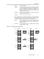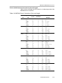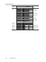
1
Chapter 4
16-Bit MSP430X CPU
This chapter describes the extended MSP430X 16-bit RISC CPU with 1-MB
memory access, its addressing modes, and instruction set. The MSP430X
CPU is implemented in all MSP430 devices that exceed 64-KB of address
space.
Topic
Page
4.1
CPU Introduction . . . . . . . . . . . . . . . . . . . . . . . . . . . . . . . . . . . . . . . . . . . . . 4-2
4.2
Interrupts . . . . . . . . . . . . . . . . . . . . . . . . . . . . . . . . . . . . . . . . . . . . . . . . . . . . 4-4
4.3
CPU Registers . . . . . . . . . . . . . . . . . . . . . . . . . . . . . . . . . . . . . . . . . . . . . . . . 4-5
4.4
Addressing Modes . . . . . . . . . . . . . . . . . . . . . . . . . . . . . . . . . . . . . . . . . . . 4-15
4.5
MSP430 and MSP430X Instructions . . . . . . . . . . . . . . . . . . . . . . . . . . . . 4-36
4.6
Instruction Set Description . . . . . . . . . . . . . . . . . . . . . . . . . . . . . . . . . . . 4-58
16-Bit MSP430X CPU
4-1
CPU Introduction
4.1 CPU Introduction
The MSP430X CPU incorporates features specifically designed for modern
programming techniques such as calculated branching, table processing and
the use of high-level languages such as C. The MSP430X CPU can address
a 1-MB address range without paging. In addition, the MSP430X CPU has
fewer interrupt overhead cycles and fewer instruction cycles in some cases
than the MSP430 CPU, while maintaining the same or better code density than
the MSP430 CPU. The MSP430X CPU is completely backwards compatible
with the MSP430 CPU.
The MSP430X CPU features include:
- RISC architecture.
- Orthogonal architecture.
- Full register access including program counter, status register and stack
pointer.
- Single-cycle register operations.
- Large register file reduces fetches to memory.
- 20-bit address bus allows direct access and branching throughout the
entire memory range without paging.
- 16-bit data bus allows direct manipulation of word-wide arguments.
- Constant generator provides the six most often used immediate values
and reduces code size.
- Direct memory-to-memory transfers without intermediate register holding.
- Byte, word, and 20-bit address-word addressing
The block diagram of the MSP430X CPU is shown in Figure 4−1.
4-2
16-Bit MSP430X CPU
CPU Introduction
Figure 4−1. MSP430X CPU Block Diagram
MDB − Memory Data Bus
19
Memory Address Bus − MAB
0
16 15
R0/PC Program Counter
0
R1/SP Pointer Stack
0
R2/SR Status Register
R3/CG2 Constant Generator
R4
General Purpose
R5
General Purpose
R6
General Purpose
R7
General Purpose
R8
General Purpose
R9
General Purpose
R10
General Purpose
R11
General Purpose
R12
General Purpose
R13
General Purpose
R14
General Purpose
R15
General Purpose
20
16
Zero, Z
Carry, C
Overflow,V
Negative,N
dst
src
16/20−bit ALU
MCLK
16-Bit MSP430X CPU
4-3
Interrupts
4.2 Interrupts
The MSP430X uses the same interrupt structure as the MSP430:
- Vectored interrupts with no polling necessary
- Interrupt vectors are located downward from address 0FFFEh
Interrupt operation for both MSP430 and MSP430X CPUs is described in
Chapter 2 System Resets, Interrupts, and Operating modes, Section 2
Interrupts. The interrupt vectors contain 16-bit addresses that point into the
lower 64-KB memory. This means all interrupt handlers must start in the lower
64-KB memory − even in MSP430X devices.
During an interrupt, the program counter and the status register are pushed
onto the stack as shown in Figure 4−2. The MSP430X architecture efficiently
stores the complete 20-bit PC value by automatically appending the PC bits
19:16 to the stored SR value on the stack. When the RETI instruction is
executed, the full 20-bit PC is restored making return from interrupt to any
address in the memory range possible.
Figure 4−2. Program Counter Storage on the Stack for Interrupts
Item n−1
SPold
PC.15:0
SP
4-4
16-Bit MSP430X CPU
PC.19:16
SR.11:0
CPU Registers
4.3 CPU Registers
The CPU incorporates sixteen registers R0 to R15. Registers R0, R1, R2, and
R3 have dedicated functions. R4 to R15 are working registers for general use.
4.3.1
The Program Counter PC
The 20-bit program counter (PC/R0) points to the next instruction to be
executed. Each instruction uses an even number of bytes (two, four, six or
eight bytes), and the PC is incremented accordingly. Instruction accesses are
performed on word boundaries, and the PC is aligned to even addresses.
Figure 4−3 shows the program counter.
Figure 4−3. Program Counter PC
19
16 15
1
Program Counter Bits 19 to 1
0
0
The PC can be addressed with all instructions and addressing modes. A few
examples:
MOV.W #LABEL,PC ; Branch to address LABEL (lower 64 KB)
MOVA
#LABEL,PC ; Branch to address LABEL (1MB memory)
MOV.W LABEL,PC ; Branch to address in word LABEL
; (lower 64 KB)
MOV.W @R14,PC
; Branch indirect to address in
; R14 (lower 64 KB)
ADDA
; Skip two words (1 MB memory)
#4,PC
The BR and CALL instructions reset the upper four PC bits to 0. Only
addresses in the lower 64-KB address range can be reached with the BR or
CALL instruction. When branching or calling, addresses beyond the lower
64-KB range can only be reached using the BRA or CALLA instructions. Also,
any instruction to directly modify the PC does so according to the used
addressing mode. For example, MOV.W #value,PC will clear the upper four
bits of the PC because it is a .W instruction.
16-Bit MSP430X CPU
4-5
CPU Registers
The program counter is automatically stored on the stack with CALL, or CALLA
instructions, and during an interrupt service routine. Figure 4−4 shows the
storage of the program counter with the return address after a CALLA
instruction. A CALL instruction stores only bits 15:0 of the PC.
Figure 4−4. Program Counter Storage on the Stack for CALLA
SPold
Item n
PC.19:16
SP
PC.15:0
The RETA instruction restores bits 19:0 of the program counter and adds 4 to
the stack pointer. The RET instruction restores bits 15:0 to the program
counter and adds 2 to the stack pointer.
4-6
16-Bit MSP430X CPU
CPU Registers
4.3.2
Stack Pointer (SP)
The 20-bit stack pointer (SP/R1) is used by the CPU to store the return
addresses of subroutine calls and interrupts. It uses a predecrement,
postincrement scheme. In addition, the SP can be used by software with all
instructions and addressing modes. Figure 4−5 shows the SP. The SP is
initialized into RAM by the user, and is always aligned to even addresses.
Figure 4−6 shows the stack usage. Figure 4−7 shows the stack usage when
20-bit address-words are pushed.
Figure 4−5. Stack Pointer
19
1
Stack Pointer Bits 19 to 1
0
0
MOV.W 2(SP),R6
; Copy Item I2 to R6
MOV.W R7,0(SP)
; Overwrite TOS with R7
PUSH
#0123h
; Put 0123h on stack
POP
R8
; R8 = 0123h
Figure 4−6. Stack Usage
Address
PUSH #0123h
POP R8
0xxxh
I1
I1
I1
0xxxh − 2
I2
I2
I2
0xxxh − 4
I3
I3
I3
SP
0123h
0xxxh − 6
SP
SP
0xxxh − 8
Figure 4−7. PUSHX.A Format on the Stack
SPold
Item n−1
Item.19:16
SP
Item.15:0
16-Bit MSP430X CPU
4-7
CPU Registers
The special cases of using the SP as an argument to the PUSH and POP
instructions are described and shown in Figure 4−8.
Figure 4−8. PUSH SP - POP SP Sequence
PUSH SP
POP SP
SPold
SP1
SP1
The stack pointer is changed after
a PUSH SP instruction.
4-8
16-Bit MSP430X CPU
SP2
SP1
The stack pointer is not changed after a POP SP
instruction. The POP SP instruction places SP1 into the
stack pointer SP (SP2=SP1)
CPU Registers
4.3.3
Status Register (SR)
The 16-bit status register (SR/R2), used as a source or destination register,
can only be used in register mode addressed with word instructions. The
remaining combinations of addressing modes are used to support the
constant generator. Figure 4−9 shows the SR bits. Do not write 20-bit values
to the SR. Unpredictable operation can result.
Figure 4−9. Status Register Bits
9
15
Reserved
8
V
7
0
SCG1
OSC CPU
SCG0
GIE
OFF OFF
N
Z C
rw-0
Table 4−1 describes the status register bits.
Table 4−1. Description of Status Register Bits
Bit
Description
Reserved
Reserved
V
Overflow bit. This bit is set when the result of an arithmetic operation
overflows the signed-variable range.
ADD(.B), ADDX(.B,.A),
ADDC(.B), ADDCX(.B.A),
ADDA
Set when:
positive + positive = negative
negative + negative = positive
otherwise reset
SUB(.B), SUBX(.B,.A),
SUBC(.B),SUBCX(.B,.A),
SUBA, CMP(.B),
CMPX(.B,.A), CMPA
Set when:
positive − negative = negative
negative − positive = positive
otherwise reset
SCG1
System clock generator 1. This bit, when set, turns off the DCO dc
generator if DCOCLK is not used for MCLK or SMCLK.
SCG0
System clock generator 0. This bit, when set, turns off the FLL+ loop
control.
OSCOFF
Oscillator Off. This bit, when set, turns off the LFXT1 crystal oscillator
when LFXT1CLK is not used for MCLK or SMCLK.
CPUOFF
CPU off. This bit, when set, turns off the CPU.
GIE
General interrupt enable. This bit, when set, enables maskable interrupts. When reset, all maskable interrupts are disabled.
N
Negative bit. This bit is set when the result of an operation is negative
and cleared when the result is positive.
16-Bit MSP430X CPU
4-9
CPU Registers
4-10
Bit
Description
Z
Zero bit. This bit is set when the result of an operation is zero and
cleared when the result is not zero.
C
Carry bit. This bit is set when the result of an operation produced a
carry and cleared when no carry occurred.
16-Bit MSP430X CPU
CPU Registers
4.3.4
The Constant Generator Registers CG1 and CG2
Six commonly used constants are generated with the constant generator
registers R2 (CG1) and R3 (CG2), without requiring an additional 16-bit word
of program code. The constants are selected with the source register
addressing modes (As), as described in Table 4−2.
Table 4−2. Values of Constant Generators CG1, CG2
Register
As
Constant
Remarks
R2
00
-
Register mode
R2
01
(0)
Absolute address mode
R2
10
00004h
+4, bit processing
R2
11
00008h
+8, bit processing
R3
00
00000h
0, word processing
R3
01
00001h
+1
R3
10
00002h
+2, bit processing
R3
11
FFh, FFFFh, FFFFFh
-1, word processing
The constant generator advantages are:
- No special instructions required
- No additional code word for the six constants
- No code memory access required to retrieve the constant
The assembler uses the constant generator automatically if one of the six
constants is used as an immediate source operand. Registers R2 and R3,
used in the constant mode, cannot be addressed explicitly; they act as
source-only registers.
Constant Generator − Expanded Instruction Set
The RISC instruction set of the MSP430 has only 27 instructions. However, the
constant generator allows the MSP430 assembler to support 24 additional,
emulated instructions. For example, the single-operand instruction:
CLR
dst
is emulated by the double-operand instruction with the same length:
MOV
R3,dst
where the #0 is replaced by the assembler, and R3 is used with As=00.
INC
dst
is replaced by:
ADD
0(R3),dst
16-Bit MSP430X CPU
4-11
CPU Registers
4.3.5
The General Purpose Registers R4 to R15
The twelve CPU registers R4 to R15, contain 8-bit, 16-bit, or 20-bit values. Any
byte-write to a CPU register clears bits 19:8. Any word-write to a register clears
bits 19:16. The only exception is the SXT instruction. The SXT instruction
extends the sign through the complete 20-bit register.
The following figures show the handling of byte, word and address-word data.
Note the reset of the leading MSBs, if a register is the destination of a byte or
word instruction.
Figure 4−10 shows byte handling (8-bit data, .B suffix). The handling is shown
for a source register and a destination memory byte and for a source memory
byte and a destination register.
Figure 4−10. Register-Byte/Byte-Register Operation
Register-Byte Operation
Byte-Register Operation
High Byte Low Byte
19 16 15
0
87
UnUnused
Register
used
Memory
High Byte
Memory
19 16 15
87
UnUnused
used
Operation
16-Bit MSP430X CPU
0
Register
Operation
Memory
4-12
Low Byte
0
0
Register
CPU Registers
Figure 4−11 and Figure 4−12 show 16-bit word handling (.W suffix). The
handling is shown for a source register and a destination memory word and
for a source memory word and a destination register.
Figure 4−11. Register-Word Operation
Register-Word Operation
High Byte Low Byte
19 16 15
0
87
UnRegister
used
Memory
Operation
Memory
Figure 4−12. Word-Register Operation
Word-Register Operation
High Byte
Low Byte
Memory
19 16 15
Unused
87
0
Register
Operation
0
Register
16-Bit MSP430X CPU
4-13
CPU Registers
Figure 4−13 and Figure 4−14 show 20-bit address-word handling (.A suffix).
The handling is shown for a source register and a destination memory
address-word and for a source memory address-word and a destination
register.
Figure 4−13. Register − Address-Word Operation
Register − Address-Word Operation
High Byte Low Byte
19 16 15
0
87
Register
Memory +2
Unused
Memory
Operation
Memory +2
0
Memory
Figure 4−14. Address-Word − Register Operation
Address-Word − Register Operation
High Byte Low Byte
19 16 15
0
87
Memory +2
Unused
Memory
Register
Operation
Register
4-14
16-Bit MSP430X CPU
CPU Registers
4.4 Addressing Modes
Seven addressing modes for the source operand and four addressing modes
for the destination operand use 16-bit or 20-bit addresses. The MSP430 and
MSP430X instructions are usable throughout the entire 1-MB memory range.
Table 4−3. Source/Destination Addressing
As/Ad
Addressing Mode
Syntax
Description
00/0
Register mode
Rn
Register contents are operand
01/1
Indexed mode
X(Rn)
(Rn + X) points to the operand. X
is stored in the next word, or
stored in combination of the
preceding extension word and the
next word.
01/1
Symbolic mode
ADDR
(PC + X) points to the operand. X
is stored in the next word, or
stored in combination of the
preceding extension word and the
next word. Indexed mode X(PC) is
used.
01/1
Absolute mode
&ADDR
The word following the instruction
contains the absolute address. X
is stored in the next word, or
stored in combination of the
preceding extension word and the
next word. Indexed mode X(SR) is
used.
10/−
Indirect register
mode
@Rn
Rn is used as a pointer to the
operand.
11/−
Indirect
autoincrement
@Rn+
Rn is used as a pointer to the
operand. Rn is incremented
afterwards by 1 for .B instructions.
by 2 for .W instructions, and by 4
for .A instructions.
11/−
Immediate mode
#N
N is stored in the next word, or
stored in combination of the
preceding extension word and the
next word. Indirect autoincrement
mode @PC+ is used.
The seven addressing modes are explained in detail in the following sections.
Most of the examples show the same addressing mode for the source and
destination, but any valid combination of source and destination addressing
modes is possible in an instruction.
Note:
Use of Labels EDE, TONI, TOM, and LEO
Throughout MSP430 documentation EDE, TONI, TOM, and LEO are used
as generic labels. They are only labels. They have no special meaning.
16-Bit MSP430X CPU
4-15
CPU Registers
4.4.1
Register Mode
Operation: The operand is the 8-, 16-, or 20-bit content of the used CPU
register.
Length:
One, two, or three words
Comment:
Valid for source and destination
Byte operation: Byte operation reads only the 8 LSBs of the source register
Rsrc and writes the result to the 8 LSBs of the destination
register Rdst. The bits Rdst.19:8 are cleared. The register
Rsrc is not modified.
Word operation:Word operation reads the 16 LSBs of the source register Rsrc
and writes the result to the 16 LSBs of the destination register
Rdst. The bits Rdst.19:16 are cleared. The register Rsrc is not
modified.
Address-Word operation: Address-word operation reads the 20 bits of the
source register Rsrc and writes the result to the 20 bits of the
destination register Rdst. The register Rsrc is not modified
SXT Exception: The SXT instruction is the only exception for register
operation. The sign of the low byte in bit 7 is extended to the
bits Rdst.19:8.
Example:
BIS.W
R5,R6 ;
This instruction logically ORs the 16-bit data contained in R5 with the 16-bit
contents of R6. R6.19:16 is cleared.
Before:
After:
Address
Space
21036h
xxxxh
21034h
D506h
Address
Space
Register
PC
R5
AA550h
21036h
xxxxh
R6
11111h
21034h
D506h
A550h.or.1111h = B551h
4-16
16-Bit MSP430X CPU
Register
PC
R5
AA550h
R6
0B551h
CPU Registers
Example:
BISX.A
R5,R6 ;
This instruction logically ORs the 20-bit data contained in R5 with the 20-bit
contents of R6.
The extension word contains the A/L-bit for 20-bit data. The instruction word
uses byte mode with bits A/L:B/W = 01. The result of the instruction is:
Before:
After:
Address
Space
Register
Address
Space
21036h
xxxxh
R5
AA550h
21036h
xxxxh
21034h
D546h
R6
11111h
21034h
D546h
21032h
1800h
21032h
1800h
PC
Register
PC
R5
AA550h
R6
BB551h
AA550h.or.11111h = BB551h
16-Bit MSP430X CPU
4-17
CPU Registers
4.4.2
Indexed Mode
The Indexed mode calculates the address of the operand by adding the signed
index to a CPU register. The Indexed mode has three addressing possibilities:
- Indexed mode in lower 64-KB memory
- MSP430 instruction with Indexed mode addressing memory above the
lower 64-KB memory.
- MSP430X instruction with Indexed mode
Indexed Mode in Lower 64 KB Memory
If the CPU register Rn points to an address in the lower 64 KB of the memory
range, the calculated memory address bits 19:16 are cleared after the addition
of the CPU register Rn and the signed 16-bit index. This means, the calculated
memory address is always located in the lower 64 KB and does not overflow
or underflow out of the lower 64-KB memory space. The RAM and the
peripheral registers can be accessed this way and existing MSP430 software
is usable without modifications as shown in Figure 4−15.
Figure 4−15. Indexed Mode in Lower 64 KB
Lower 64 KB.
Rn.19:16 = 0
19 16 15
FFFFF
0
CPU Register
Rn
0
Rn.19:0
00000
4-18
ÇÇÇÇÇ
ÇÇÇÇÇ
ÇÇÇÇÇ
ÇÇÇÇÇ
ÇÇÇÇÇ
Lower 64KB
10000
0FFFF
S
16-bit byte index
16-bit
signed index
16-bit signed add
0
Memory address
Length:
Two or three words
Operation:
The signed 16-bit index is located in the next word after the
instruction and is added to the CPU register Rn. The resulting
bits 19:16 are cleared giving a truncated 16-bit memory
address, which points to an operand address in the range
00000h to 0FFFFh. The operand is the content of the
addressed memory location.
Comment:
Valid for source and destination. The assembler calculates
the register index and inserts it.
16-Bit MSP430X CPU
CPU Registers
Example:
ADD.B
1000h(R5),0F000h(R6);
The previous instruction adds the 8-bit data contained in source byte
1000h(R5) and the destination byte 0F000h(R6) and places the result into the
destination byte. Source and destination bytes are both located in the lower
64 KB due to the cleared bits 19:16 of registers R5 and R6.
Source:
The byte pointed to by R5 + 1000h results in address 0479Ch
+ 1000h = 0579Ch after truncation to a 16-bit address.
Destination:
The byte pointed to by R6 + F000h results in address 01778h
+ F000h = 00778h after truncation to a 16-bit address.
Before:
After:
Address
Space
Register
Address
Space
Register
1103Ah
xxxxh
R5
0479Ch
1103Ah
xxxxh
PC R5
0479Ch
11038h
F000h
R6
01778h
11038h
F000h
R6
01778h
11036h
1000h
11036h
1000h
11034h
55D6h
11034h
55D6h
0077Ah
xxxxh
0077Ah
xxxxh
00778h
xx45h
01778h
+F000h
00778h
00778h
xx77h
0579Eh
xxxxh
0579Eh
xxxxh
0579Ch
xx32h
0479Ch
+1000h
0579Ch
0579Ch
xx32h
PC
32h
+45h
77h
16-Bit MSP430X CPU
src
dst
Sum
4-19
CPU Registers
MSP430 Instruction with Indexed Mode in Upper Memory
If the CPU register Rn points to an address above the lower 64-KB memory,
the Rn bits 19:16 are used for the address calculation of the operand. The
operand may be located in memory in the range Rn ±32 KB, because the
index, X, is a signed 16-bit value. In this case, the address of the operand can
overflow or underflow into the lower 64-KB memory space. See Figure 4−16
and Figure 4−17.
Figure 4−16. Indexed Mode in Upper Memory
Upper Memory
Rn.19:16 > 0
19
FFFFF
16 15
0
CPU Register
Rn
1 ... 15
Rn ±32 KB
S
S
16-bit byte index
Lower 64 KB
10000
0FFFF
20-bit signed add
Memory address
00000
Figure 4−17. Overflow and Underflow for the Indexed Mode
Rn.19:0
FFFFF
ÇÇÇÇÇÇ
ÇÇÇÇÇÇ
ÇÇÇÇÇÇ
ÇÇÇÇÇÇ
ÇÇÇÇÇÇ
ÇÇÇÇÇÇ
ÇÇÇÇÇÇ
ÇÇÇÇÇÇ
±32KB
Rn.19:0
0000C
4-20
16-Bit MSP430X CPU
Lower 64 KB
10000
0,FFFF
Rn.19:0
16-bit signed index
(sign extended to
20 bits)
Rn.19:0
ÇÇÇÇÇÇ
ÇÇÇÇÇÇ
ÇÇÇÇÇÇ
ÇÇÇÇÇÇ
ÇÇÇÇÇÇ
ÇÇÇÇÇÇ
ÇÇÇÇÇÇ
ÇÇÇÇÇÇ
±32KB
Rn.19:0
CPU Registers
Length:
Two or three words
Operation:
The sign-extended 16-bit index in the next word after the
instruction is added to the 20 bits of the CPU register Rn. This
delivers a 20-bit address, which points to an address in the
range 0 to FFFFFh. The operand is the content of the
addressed memory location.
Comment:
Valid for source and destination. The assembler calculates
the register index and inserts it.
Example:
ADD.W
8346h(R5),2100h(R6);
This instruction adds the 16-bit data contained in the source and the
destination addresses and places the 16-bit result into the destination. Source
and destination operand can be located in the entire address range.
Source:
The word pointed to by R5 + 8346h. The negative index
8346h is sign-extended, which results in address 23456h +
F8346h = 1B79Ch.
Destination:
The word pointed to by R6 + 2100h results in address
15678h + 2100h = 17778h.
Figure 4−18. Example for the Indexed Mode
Before:
After:
Address
Space
Register
Address
Space
Register
1103Ah
xxxxh
R5
23456h
1103Ah
xxxxh
PC R5
23456h
11038h
2100h
R6
15678h
11038h
2100h
R6
15678h
11036h
8346h
11036h
8346h
11034h
5596h
11034h
5596h
1777Ah
xxxxh
1777Ah
xxxxh
17778h
2345h
15678h
+02100h
17778h
17778h
7777h
1B79Eh
xxxxh
1B79Eh
xxxxh
1B79Ch
5432h
23456h
+F8346h
1B79Ch
1B79Ch
5432h
PC
05432h
+02345h
07777h
16-Bit MSP430X CPU
src
dst
Sum
4-21
CPU Registers
MSP430X Instruction with Indexed Mode
When using an MSP430X instruction with Indexed mode, the operand can be
located anywhere in the range of Rn ± 19 bits.
Length:
Three or four words
Operation:
The operand address is the sum of the 20-bit CPU register
content and the 20-bit index. The four MSBs of the index are
contained in the extension word, the 16 LSBs are contained
in the word following the instruction. The CPU register is not
modified.
Comment:
Valid for source and destination. The assembler calculates
the register index and inserts it.
Example:
ADDX.A
12346h(R5),32100h(R6) ;
This instruction adds the 20-bit data contained in the source and the
destination addresses and places the result into the destination.
4-22
Source:
Two words pointed to by R5 + 12346h which results in
address 23456h + 12346h = 3579Ch.
Destination:
Two words pointed to by R6 + 32100h which results in
address 45678h + 32100h = 77778h.
16-Bit MSP430X CPU
CPU Registers
The extension word contains the MSBs of the source index and of the
destination index and the A/L-bit for 20-bit data. The instruction word uses byte
mode due to the 20-bit data length with bits A/L:B/W = 01.
Before:
After:
Address
Space
Register
Address
Space
Register
2103Ah
xxxxh
R5
23456h
2103Ah
xxxxh
PC R5
23456h
21038h
2100h
R6
45678h
21038h
2100h
R6
45678h
21036h
2346h
21036h
2346h
21034h
55D6h
21034h
55D6h
21032h
1883h
21032h
1883h
7777Ah
0001h
7777Ah
0007h
77778h
2345h
77778h
7777h
3579Eh
0006h
3579Eh
0006h
3579Ch
5432h
3579Ch
5432h
PC
45678h
+32100h
77778h
23456h
+12346h
3579Ch
65432h
+12345h
77777h
16-Bit MSP430X CPU
src
dst
Sum
4-23
CPU Registers
4.4.3
Symbolic Mode
The Symbolic mode calculates the address of the operand by adding the
signed index to the program counter. The Symbolic mode has three
addressing possibilities:
- Symbolic mode in lower 64-KB memory
- MSP430 instruction with symbolic mode addressing memory above the
lower 64-KB memory.
- MSP430X instruction with symbolic mode
Symbolic Mode in Lower 64 KB
If the PC points to an address in the lower 64 KB of the memory range, the
calculated memory address bits 19:16 are cleared after the addition of the PC
and the signed 16-bit index. This means, the calculated memory address is
always located in the lower 64 KB and does not overflow or underflow out of
the lower 64-KB memory space. The RAM and the peripheral registers can be
accessed this way and existing MSP430 software is usable without
modifications as shown in Figure 4−15.
Figure 4−19. Symbolic Mode Running in Lower 64 KB
Lower 64 KB.
PC.19:16 = 0
19 16 15
FFFFF
0
Program
counter PC
0
S
ÇÇÇÇÇ
ÇÇÇÇÇ
ÇÇÇÇÇ
ÇÇÇÇÇ
ÇÇÇÇÇ
16-bit byte index
16-bit signed
PC index
PC.19:0
00000
Lower 64 KB
10000
0FFFF
16-bit signed add
0
Memory address
Operation: The signed 16-bit index in the next word after the instruction is
added temporarily to the PC. The resulting bits 19:16 are cleared giving a
truncated 16-bit memory address, which points to an operand address in the
range 00000h, to 0FFFFh. The operand is the content of the addressed
memory location.
4-24
Length:
Two or three words
Comment:
Valid for source and destination. The assembler calculates
the PC index and inserts it.
Example:
ADD.B
16-Bit MSP430X CPU
EDE,TONI ;
CPU Registers
The previous instruction adds the 8-bit data contained in source byte EDE and
destination byte TONI and places the result into the destination byte TONI.
Bytes EDE and TONI and the program are located in the lower 64 KB.
Source:
Byte EDE located at address 0,579Ch, pointed to by PC +
4766h where the PC index 4766h is the result of 0579Ch −
01036h = 04766h. Address 01036h is the location of the index
for this example.
Destination:
Byte TONI located at address 00778h, pointed to by PC +
F740h,
is
the
truncated
16-bit
result
of
00778h − 1038h = FF740h. Address 01038h is the location
of the index for this example.
Before:
After:
Address
Space
Address
Space
0103Ah
xxxxh
0103Ah
xxxxh
01038h
F740h
01038h
F740h
01036h
4766h
01036h
4766h
01034h
05D0h
01034h
50D0h
0077Ah
xxxxh
0077Ah
xxxxh
00778h
xx45h
00778h
xx77h
0579Eh
xxxxh
0579Eh
xxxxh
0579Ch
xx32h
0579Ch
xx32h
PC
01038h
+0F740h
00778h
01036h
+04766h
0579Ch
PC
32h
+45h
77h
16-Bit MSP430X CPU
src
dst
Sum
4-25
CPU Registers
MSP430 Instruction with Symbolic Mode in Upper Memory
If the PC points to an address above the lower 64-KB memory, the PC bits
19:16 are used for the address calculation of the operand. The operand may
be located in memory in the range PC ±32 KB, because the index, X, is a
signed 16-bit value. In this case, the address of the operand can overflow or
underflow into the lower 64-KB memory space as shown in Figure 4−20 and
Figure 4−21.
Figure 4−20. Symbolic Mode Running in Upper Memory
Upper Memory
PC.19:16 > 0
19
FFFFF
16 15
0
Program
counter PC
1 ... 15
PC ±32 KB
S
S
16-bit byte index
Lower 64 KB
10000
0FFFF
20-bit signed add
Memory address
00000
Figure 4−21. Overflow and Underflow for the Symbolic Mode
±32KB
ÇÇÇÇÇÇ
ÇÇÇÇÇÇ
ÇÇÇÇÇÇ
ÇÇÇÇÇÇ
ÇÇÇÇÇÇ
ÇÇÇÇÇÇ
ÇÇÇÇÇÇ
ÇÇÇÇÇÇ
0000C
4-26
16-Bit MSP430X CPU
ÇÇÇÇÇÇ
ÇÇÇÇÇÇ
ÇÇÇÇÇÇ
ÇÇÇÇÇÇ
ÇÇÇÇÇÇ
PC.19:0
Lower 64 KB
10000
0FFFF
PC.19:0
ÇÇÇÇÇÇ
ÇÇÇÇÇÇ
ÇÇÇÇÇÇ
PC.19:0
FFFFF
PC.19:0
16-bit signed PC
index (sign
extended to
20 bits)
±32KB
PC.19:0
CPU Registers
Length:
Two or three words
Operation:
The sign-extended 16-bit index in the next word after the
instruction is added to the 20 bits of the PC. This delivers a
20-bit address, which points to an address in the range 0 to
FFFFFh. The operand is the content of the addressed
memory location.
Comment:
Valid for source and destination. The assembler calculates
the PC index and inserts it
Example:
ADD.W
EDE,&TONI ;
This instruction adds the 16-bit data contained in source word EDE and
destination word TONI and places the 16-bit result into the destination word
TONI. For this example, the instruction is located at address 2,F034h.
Source:
Word EDE at address 3379Ch, pointed to by PC + 4766h
which is the 16-bit result of 3379Ch − 2F036h = 04766h.
Address 2F036h is the location of the index for this example.
Destination:
Word TONI located at address 00778h pointed to by the
absolute address 00778h.
Before:
After:
Address
Space
Address
Space
2F03Ah
xxxxh
2F03Ah
xxxxh
2F038h
0778h
2F038h
0778h
2F036h
4766h
2F036h
4766h
2F034h
5092h
2F034h
5092h
3379Eh
xxxxh
3379Eh
xxxxh
3379Ch
5432h
3379Ch
5432h
0077Ah
xxxxh
0077Ah
xxxxh
00778h
2345h
00778h
7777h
PC
2F036h
+04766h
3379Ch
PC
5432h
+2345h
7777h
16-Bit MSP430X CPU
src
dst
Sum
4-27
CPU Registers
MSP430X Instruction with Symbolic Mode
When using an MSP430X instruction with Symbolic mode, the operand can
be located anywhere in the range of PC ± 19 bits.
Length:
Three or four words
Operation:
The operand address is the sum of the 20-bit PC and the
20-bit index. The four MSBs of the index are contained in the
extension word, the 16 LSBs are contained in the word
following the instruction.
Comment:
Valid for source and destination. The assembler calculates
the register index and inserts it.
Example:
ADDX.B
EDE,TONI ;
The instruction adds the 8-bit data contained in source byte EDE and
destination byte TONI and places the result into the destination byte TONI.
Source:
Byte EDE located at address 3579Ch, pointed to by
PC + 14766h,
is
the
20-bit
result
of
3579Ch - 21036h = 14766h. Address 21036h is the address
of the index in this example.
Destination:
Byte TONI located at address 77778h, pointed to by
PC + 56740h,
is
the
20-bit
result
of
77778h - 21038h = 56740h. Address 21038h is the address
of the index in this example..
Before:
4-28
Address Space
After:
Address Space
2103Ah
xxxxh
2103Ah
xxxxh
21038h
6740h
21038h
6740h
21036h
4766h
21036h
4766h
21034h
50D0h
21034h
50D0h
21032h
18C5h
21032h
18C5h
7777Ah
xxxxh
7777Ah
xxxxh
77778h
xx45h
21038h
+56740h
77778h
77778h
xx77h
3579Eh
xxxxh
3579Eh
xxxxh
3579Ch
xx32h
21036h
+14766h
3579Ch
3579Ch
xx32h
16-Bit MSP430X CPU
PC
PC
32h
+45h
77h
src
dst
Sum
CPU Registers
4.4.4
Absolute Mode
The Absolute mode uses the contents of the word following the instruction as
the address of the operand. The Absolute mode has two addressing
possibilities:
- Absolute mode in lower 64-KB memory
- MSP430X instruction with Absolute mode
16-Bit MSP430X CPU
4-29
CPU Registers
Absolute Mode in Lower 64 KB
If an MSP430 instruction is used with Absolute addressing mode, the absolute
address is a 16-bit value and therefore points to an address in the lower 64 KB
of the memory range. The address is calculated as an index from 0 and is
stored in the word following the instruction The RAM and the peripheral
registers can be accessed this way and existing MSP430 software is usable
without modifications.
Length:
Two or three words
Operation:
The operand is the content of the addressed memory
location.
Comment:
Valid for source and destination. The assembler calculates
the index from 0 and inserts it
Example:
ADD.W
&EDE,&TONI ;
This instruction adds the 16-bit data contained in the absolute source and
destination addresses and places the result into the destination.
Source:
Word at address EDE
Destination:
Word at address TONI
Before: Address Space
4-30
After:
Address Space
2103Ah
xxxxh
2103Ah
xxxxh
21038h
7778h
21038h
7778h
21036h
579Ch
21036h
579Ch
21034h
5292h
21034h
5292h
0777Ah
xxxxh
0777Ah
xxxxh
07778h
2345h
07778h
7777h
0579Eh
xxxxh
0579Eh
xxxxh
0579Ch
5432h
0579Ch
5432h
16-Bit MSP430X CPU
PC
PC
5432h
+2345h
7777h
src
dst
Sum
CPU Registers
MSP430X Instruction with Absolute Mode
If an MSP430X instruction is used with Absolute addressing mode, the
absolute address is a 20-bit value and therefore points to any address in the
memory range. The address value is calculated as an index from 0. The four
MSBs of the index are contained in the extension word, and the 16 LSBs are
contained in the word following the instruction.
Length:
Three or four words
Operation:
The operand is the content of the addressed memory
location.
Comment:
Valid for source and destination. The assembler calculates
the index from 0 and inserts it
Example:
ADDX.A
&EDE,&TONI ;
This instruction adds the 20-bit data contained in the absolute source and
destination addresses and places the result into the destination.
Source:
Two words beginning with address EDE
Destination:
Two words beginning with address TONI
Before:
After:
Address
Space
Address
Space
2103Ah
xxxxh
2103Ah
xxxxh
21038h
7778h
21038h
7778h
21036h
579Ch
21036h
579Ch
21034h
52D2h
21034h
52D2h
21032h
1987h
21032h
1987h
7777Ah
0001h
7777Ah
0007h
77778h
2345h
77778h
7777h
3579Eh
0006h
3579Eh
0006h
3579Ch
5432h
3579Ch
5432h
PC
PC
65432h
+12345h
77777h
16-Bit MSP430X CPU
src
dst
Sum
4-31
CPU Registers
4.4.5
Indirect Register Mode
The Indirect Register mode uses the contents of the CPU register Rsrc as the
source operand. The Indirect Register mode always uses a 20-bit address.
Length:
One, two, or three words
Operation:
The operand is the content the addressed memory location.
The source register Rsrc is not modified.
Comment:
Valid only for the source operand. The substitute for the
destination operand is 0(Rdst).
Example:
ADDX.W
@R5,2100h(R6)
This instruction adds the two 16-bit operands contained in the source and the
destination addresses and places the result into the destination.
Source:
Word pointed to by R5. R5 contains address 3,579Ch for this
example.
Destination:
Word pointed to by R6 + 2100h which results in address
45678h + 2100h = 7778h.
Before:
After:
Address
Space
4-32
Register
Address
Space
Register
21038h
xxxxh
R5
3579Ch
21038h
xxxxh
PC R5
3579Ch
21036h
2100h
R6
45678h
21036h
2100h
R6
45678h
21034h
55A6h
21034h
55A6h
4777Ah
xxxxh
4777Ah
xxxxh
47778h
2345h
47778h
7777h
3579Eh
xxxxh
3579Eh
xxxxh
3579Ch
5432h
3579Ch
5432h
16-Bit MSP430X CPU
PC
45678h
+02100h
47778h
R5
5432h
+2345h
7777h
R5
src
dst
Sum
CPU Registers
4.4.6
Indirect, Autoincrement Mode
The Indirect Autoincrement mode uses the contents of the CPU register Rsrc
as the source operand. Rsrc is then automatically incremented by 1 for byte
instructions, by 2 for word instructions, and by 4 for address-word instructions
immediately after accessing the source operand. If the same register is used
for source and destination, it contains the incremented address for the
destination access. Indirect Autoincrement mode always uses 20-bit
addresses.
Length:
One, two, or three words
Operation:
The operand is the content of the addressed memory
location.
Comment:
Valid only for the source operand.
Example:
ADD.B
@R5+,0(R6)
This instruction adds the 8-bit data contained in the source and the destination
addresses and places the result into the destination.
Source:
Byte pointed to by R5. R5 contains address 3,579Ch for this
example.
Destination:
Byte pointed to by R6 + 0h which results in address 0778h for
this example.
Before:
After:
Address
Space
Register
Address
Space
Register
21038h
xxxxh
R5
3579Ch
21038h
xxxxh
PC R5
3579Dh
21036h
0000h
R6
00778h
21036h
0000h
R6
00778h
21034h
55F6h
21034h
55F6h
0077Ah
xxxxh
0077Ah
xxxxh
00778h
xx45h
00778h
xx77h
3579Dh
xxh
3579Dh
xxh
3579Ch
32h
3579Ch
xx32h
PC
00778h
+0000h
00778h
R5
32h
+45h
77h
src
dst
Sum
R5
16-Bit MSP430X CPU
4-33
CPU Registers
4.4.7
Immediate Mode
The Immediate mode allows accessing constants as operands by including
the constant in the memory location following the instruction. The program
counter PC is used with the Indirect Autoincrement mode. The PC points to
the immediate value contained in the next word. After the fetching of the
immediate operand, the PC is incremented by 2 for byte, word, or
address-word instructions. The Immediate mode has two addressing
possibilities:
- 8- or 16-bit constants with MSP430 instructions
- 20-bit constants with MSP430X instruction
MSP430 Instructions with Immediate Mode
If an MSP430 instruction is used with Immediate addressing mode, the
constant is an 8- or 16-bit value and is stored in the word following the
instruction.
Length:
Two or three words. One word less if a constant of the
constant generator can be used for the immediate operand.
Operation:
The 16-bit immediate source operand is used together with
the 16-bit destination operand.
Comment:
Valid only for the source operand.
Example:
ADD
#3456h,&TONI
This instruction adds the 16-bit immediate operand 3456h to the data in the
destination address TONI.
Source:
16-bit immediate value 3456h.
Destination:
Word at address TONI.
Before:
After:
Address
Space
Address
Space
4-34
2103Ah
xxxxh
2103Ah
xxxxh
21038h
0778h
21038h
0778h
21036h
3456h
21036h
3456h
21034h
50B2h
21034h
50B2h
0077Ah
xxxxh
0077Ah
xxxxh
00778h
2345h
00778h
579Bh
16-Bit MSP430X CPU
PC
PC
3456h
+2345h
579Bh
src
dst
Sum
CPU Registers
MSP430X Instructions with Immediate Mode
If an MSP430X instruction is used with immediate addressing mode, the
constant is a 20-bit value. The 4 MSBs of the constant are stored in the
extension word and the 16 LSBs of the constant are stored in the word
following the instruction.
Length:
Three or four words. One word less if a constant of the
constant generator can be used for the immediate operand.
Operation:
The 20-bit immediate source operand is used together with
the 20-bit destination operand.
Comment:
Valid only for the source operand.
Example:
ADDX.A
#23456h,&TONI ;
This instruction adds the 20-bit immediate operand 23456h to the data in the
destination address TONI.
Source:
20-bit immediate value 23456h.
Destination:
Two words beginning with address TONI.
Before:
After:
Address
Space
Address
Space
2103Ah
xxxxh
2103Ah
xxxxh
21038h
7778h
21038h
7778h
21036h
3456h
21036h
3456h
21034h
50F2h
21034h
50F2h
21032h
1907h
21032h
1907h
7777Ah
0001h
7777Ah
0003h
77778h
2345h
77778h
579Bh
PC
PC
23456h
+12345h
3579Bh
16-Bit MSP430X CPU
src
dst
Sum
4-35
MSP430 and MSP430X Instructions
4.5 MSP430 and MSP430X Instructions
MSP430 instructions are the 27 implemented instructions of the MSP430
CPU. These instructions are used throughout the 1-MB memory range unless
their 16-bit capability is exceeded. The MSP430X instructions are used when
the addressing of the operands or the data length exceeds the 16-bit capability
of the MSP430 instructions.
There are three possibilities when choosing between an MSP430 and
MSP430X instruction:
- To use only the MSP430 instructions: The only exceptions are the CALLA
and the RETA instruction. This can be done if a few, simple rules are met:
J
Placement of all constants, variables, arrays, tables, and data in the
lower 64 KB. This allows the use of MSP430 instructions with 16-bit
addressing for all data accesses. No pointers with 20-bit addresses
are needed.
J Placement of subroutine constants immediately after the subroutine
code. This allows the use of the symbolic addressing mode with its
16-bit index to reach addresses within the range of PC ±32 KB.
- To use only MSP430X instructions: The disadvantages of this method are
the reduced speed due to the additional CPU cycles and the increased
program space due to the necessary extension word for any double
operand instruction.
- Use the best fitting instruction where needed
The following sections list and describe the MSP430 and MSP430X
instructions.
4-36
16-Bit MSP430X CPU
MSP430 and MSP430X Instructions
4.5.1
MSP430 Instructions
The MSP430 instructions can be used, regardless if the program resides in the
lower 64 KB or beyond it. The only exceptions are the instructions CALL and
RET which are limited to the lower 64 KB address range. CALLA and RETA
instructions have been added to the MSP430X CPU to handle subroutines in
the entire address range with no code size overhead.
MSP430 Double Operand (Format I) Instructions
Figure 4−22 shows the format of the MSP430 double operand instructions.
Source and destination words are appended for the Indexed, Symbolic,
Absolute and Immediate modes. Table 4−4 lists the twelve MSP430 double
operand instructions.
Figure 4−22. MSP430 Double Operand Instruction Format
15
12
11
8
Op-code
Rsrc
7
6
Ad
B/W
5
4
0
As
Rdst
Source or Destination 15:0
Destination 15:0
Table 4−4. MSP430 Double Operand Instructions
Mnemonic
S-Reg,
g,
D-Reg
Operation
MOV(.B)
src,dst
ADD(.B)
Status Bits
V
N
Z
C
src → dst
−
−
−
−
src,dst
src + dst → dst
*
*
*
*
ADDC(.B)
src,dst
src + dst + C → dst
*
*
*
*
SUB(.B)
src,dst
dst + .not.src + 1 → dst
*
*
*
*
SUBC(.B)
src,dst
dst + .not.src + C → dst
*
*
*
*
CMP(.B)
src,dst
dst − src
*
*
*
*
DADD(.B)
src,dst
src + dst + C → dst (decimally)
*
*
*
*
BIT(.B)
src,dst
src .and. dst
0
*
*
Z
BIC(.B)
src,dst
.not.src .and. dst → dst
−
−
−
−
BIS(.B)
src,dst
src .or. dst → dst
−
−
−
−
XOR(.B)
src,dst
src .xor. dst → dst
*
*
*
Z
AND(.B)
src,dst
src .and. dst → dst
0
*
*
Z
*
The status bit is affected
−
The status bit is not affected
0
The status bit is cleared
1
The status bit is set
16-Bit MSP430X CPU
4-37
MSP430 and MSP430X Instructions
Single Operand (Format II) Instructions
Figure 4−23 shows the format for MSP430 single operand instructions, except
RETI. The destination word is appended for the Indexed, Symbolic, Absolute
and Immediate modes .Table 4−5 lists the seven single operand instructions.
Figure 4−23. MSP430 Single Operand Instructions
15
7
Op-code
6
5
B/W
4
0
Ad
Rdst
Destination 15:0
Table 4−5. MSP430 Single Operand Instructions
S-Reg,
D Reg
D-Reg
Operation
RRC(.B)
dst
C → MSB →.......LSB → C
*
*
*
*
RRA(.B)
dst
MSB → MSB →....LSB → C
0
*
*
*
PUSH(.B)
src
SP − 2 → SP, src → @SP
−
−
−
−
SWPB
dst
bit 15…bit 8 ⇔ bit 7…bit 0
−
−
−
−
CALL
dst
Call subroutine in lower 64 KB
−
−
−
−
TOS → SR, SP + 2 → SP
*
*
*
*
0
*
*
Z
Mnemonic
RETI
Status Bits
V
N
Z
C
TOS → PC,SP + 2 → SP
SXT
4-38
dst
Register mode:
bit 7 → bit 8 …bit 19
Other modes:
bit 7 → bit 8 …bit 15
*
The status bit is affected
−
The status bit is not affected
0
The status bit is cleared
1
The status bit is set
16-Bit MSP430X CPU
MSP430 and MSP430X Instructions
Jumps
Figure 4−24 shows the format for MSP430 and MSP430X jump instructions.
The signed 10-bit word offset of the jump instruction is multiplied by two,
sign-extended to a 20-bit address, and added to the 20-bit program counter.
This allows jumps in a range of -511 to +512 words relative to the program
counter in the full 20-bit address space Jumps do not affect the status bits.
Table 4−6 lists and describes the eight jump instructions.
Figure 4−24. Format of the Conditional Jump Instructions
15
13
Op-Code
12
10
Condition
9
8
S
0
10-Bit Signed PC Offset
Table 4−6. Conditional Jump Instructions
Mnemonic
S-Reg, D-Reg
Operation
JEQ/JZ
Label
Jump to label if zero bit is set
JNE/JNZ
Label
Jump to label if zero bit is reset
JC
Label
Jump to label if carry bit is set
JNC
Label
Jump to label if carry bit is reset
JN
Label
Jump to label if negative bit is set
JGE
Label
Jump to label if (N .XOR. V) = 0
JL
Label
Jump to label if (N .XOR. V) = 1
JMP
Label
Jump to label unconditionally
16-Bit MSP430X CPU
4-39
MSP430 and MSP430X Instructions
Emulated Instructions
In addition to the MSP430 and MSP430X instructions, emulated instructions
are instructions that make code easier to write and read, but do not have
op-codes themselves. Instead, they are replaced automatically by the
assembler with a core instruction. There is no code or performance penalty for
using emulated instructions. The emulated instructions are listed in Table 4−7.
Table 4−7. Emulated Instructions
Instruction
Explanation
ADC(.B) dst
Add Carry to dst
ADDC(.B) #0,dst
*
*
*
*
BR
Branch indirectly dst
MOV dst,PC
-
-
-
-
dst
V
N Z
C
Clear dst
MOV(.B) #0,dst
-
-
-
-
CLRC
Clear Carry bit
BIC #1,SR
-
-
-
0
CLRN
Clear Negative bit
BIC #4,SR
-
0
-
-
CLRZ
Clear Zero bit
BIC #2,SR
-
-
0
-
DADC(.B) dst
Add Carry to dst decimally
DADD(.B) #0,dst
*
*
*
*
DEC(.B) dst
Decrement dst by 1
SUB(.B) #1,dst
*
*
*
*
DECD(.B) dst
Decrement dst by 2
SUB(.B) #2,dst
*
*
*
*
DINT
Disable interrupt
BIC #8,SR
-
-
-
-
EINT
Enable interrupt
BIS #8,SR
-
-
-
-
INC(.B) dst
Increment dst by 1
ADD(.B) #1,dst
*
*
*
*
INCD(.B) dst
Increment dst by 2
ADD(.B) #2,dst
*
*
*
*
INV(.B) dst
Invert dst
XOR(.B) #-1,dst
*
*
*
*
NOP
No operation
MOV R3,R3
-
-
-
-
POP dst
Pop operand from stack
MOV @SP+,dst
-
-
-
-
RET
Return from subroutine
MOV @SP+,PC
-
-
-
-
RLA(.B) dst
Shift left dst arithmetically
ADD(.B) dst,dst
*
*
*
*
RLC(.B) dst
Shift left dst
logically through Carry
ADDC(.B) dst,dst
*
*
*
*
SBC(.B) dst
Subtract Carry from dst
SUBC(.B) #0,dst
*
*
*
*
SETC
Set Carry bit
BIS #1,SR
-
-
-
1
SETN
Set Negative bit
BIS #4,SR
-
1
-
-
SETZ
Set Zero bit
BIS #2,SR
-
-
1
-
TST(.B) dst
Test dst
(compare with 0)
CMP(.B) #0,dst
0
*
*
1
CLR(.B)
4-40
Emulation
dst
16-Bit MSP430X CPU
MSP430 and MSP430X Instructions
MSP430 Instruction Execution
The number of CPU clock cycles required for an instruction depends on the
instruction format and the addressing modes used - not the instruction itself.
The number of clock cycles refers to MCLK.
Instruction Cycles and Length for Interrupt, Reset, and Subroutines
Table 4−8 lists the length and the CPU cycles for reset, interrupts and
subroutines.
Table 4−8. Interrupt, Return and Reset Cycles and Length
Execution Time
MCLK Cycles
Length of
Instruction (Words)
Return from interrupt RETI
3†
1
Return from subroutine RET
3
1
Interrupt request service (cycles
needed before 1st instruction)
5‡
-
WDT reset
4
-
Reset (RST/NMI)
4
-
Action
†
‡
The cycle count in MSP430 CPU is 5.
The cycle count in MSP430 CPU is 6.
16-Bit MSP430X CPU
4-41
MSP430 and MSP430X Instructions
Format-II (Single Operand) Instruction Cycles and Lengths
Table 4−9 lists the length and the CPU cycles for all addressing modes of the
MSP430 single operand instructions.
Table 4−9. MSP430 Format-II Instruction Cycles and Length
Length of
Instruction
No. of Cycles
PUSH
CALL
Length of
Instruction
1
3
3†
1
SWPB R5
3
3†
4
1
RRC @R9
3
3†
4‡
1
SWPB @R10+
n.a.
3†
4‡
2
CALL #LABEL
4
4‡
4‡
2
CALL 2(R7)
EDE
4
4‡
4‡
2
PUSH EDE
&EDE
4
4‡
4‡
2
SXT &EDE
Addressing
Mode
Rn
@Rn
@Rn+
#N
X(Rn)
†
‡
Example
RRA, RRC
SWPB, SXT
Example
The cycle count in MSP430 CPU is 4.
The cycle count in MSP430 CPU is 5. Also, the cycle count is 5 for X(Rn) addressing mode, when
Rn = SP.
Jump Instructions. Cycles and Lengths
All jump instructions require one code word, and take two CPU cycles to
execute, regardless of whether the jump is taken or not.
4-42
16-Bit MSP430X CPU
MSP430 and MSP430X Instructions
Format-I (Double Operand) Instruction Cycles and Lengths
Table 4−10 lists the length and CPU cycles for all addressing modes of the
MSP430 format-I instructions.
Table 4−10.MSP430 Format-I Instructions Cycles and Length
No. of
Cycles
Length
g of
Instruction
1
1
PC
2
1
BR
R9
x(Rm)
4†
2
ADD
R5,4(R6)
EDE
4†
2
XOR
R8,EDE
&EDE
4†
2
MOV
R5,&EDE
Rm
2
1
AND
@R4,R5
PC
3
1
BR
@R8
x(Rm)
5†
2
XOR
@R5,8(R6)
EDE
5†
2
MOV
@R5,EDE
&EDE
5†
2
XOR
@R5,&EDE
Rm
2
1
ADD
@R5+,R6
PC
3
1
BR
@R9+
x(Rm)
5†
2
XOR
@R5,8(R6)
EDE
5†
2
MOV
@R9+,EDE
&EDE
5†
2
MOV
@R9+,&EDE
Rm
2
2
MOV
#20,R9
PC
3
2
BR
#2AEh
x(Rm)
5†
3
MOV
#0300h,0(SP)
EDE
5†
3
ADD
#33,EDE
&EDE
5†
3
ADD
#33,&EDE
Rm
3
2
MOV
2(R5),R7
PC
3
2
BR
2(R6)
TONI
6†
3
MOV
4(R7),TONI
x(Rm)
6†
3
ADD
4(R4),6(R9)
&TONI
6†
3
MOV
2(R4),&TONI
Rm
3
2
AND
EDE,R6
PC
3
2
BR
EDE
TONI
6†
3
CMP
EDE,TONI
x(Rm)
6†
3
MOV
EDE,0(SP)
&TONI
6†
3
MOV
EDE,&TONI
Rm
3
2
MOV
&EDE,R8
PC
3
2
BR
&EDE
TONI
6†
3
MOV
&EDE,TONI
x(Rm)
6†
3
MOV
&EDE,0(SP)
&TONI
6†
3
MOV
&EDE,&TONI
Addressing Mode
Src
Rn
@Rn
@Rn+
#N
x(Rn)
( )
EDE
&EDE
†
Dst
Rm
MOV
Example
R5,R8
MOV, BIT, and CMP instructions execute in 1 fewer cycle
16-Bit MSP430X CPU
4-43
MSP430X Extended Instructions
4.5.2
MSP430X Extended Instructions
The extended MSP430X instructions give the MSP430X CPU full access to its
20-bit address space. Most MSP430X instructions require an additional word
of op-code called the extension word. Some extended instructions do not
require an additional word and are noted in the instruction description. All
addresses, indexes and immediate numbers have 20-bit values, when
preceded by the extension word.
There are two types of extension word:
- Register/register mode for Format-I instructions and register mode for
Format-II instructions.
- Extension word for all other address mode combinations.
4-44
16-Bit MSP430X CPU
MSP430X Extended Instructions
Register Mode Extension Word
The register mode extension word is shown in Figure 4−25 and described in
Table 4−11. An example is shown in Figure 4−27.
Figure 4−25. The Extension Word for Register Modes
15
12
11
10
1
0001
9
00
8
7
6
5
4
ZC
#
A/L
0
0
3
0
(n−1)/Rn
Table 4−11. Description of the Extension Word Bits for Register Mode
Bit
Description
15:11
Extension word op-code. Op-codes 1800h to 1FFFh are extension
words.
10:9
Reserved
ZC
Zero carry bit.
#
A/L
0:
The executed instruction uses the status of the carry bit C.
1:
The executed instruction uses the carry bit as 0. The carry bit will
be defined by the result of the final operation after instruction execution.
Repetition bit.
0:
The number of instruction repetitions is set by extension-word bits
3:0.
1:
The number of instructions repetitions is defined by the value of the
four LSBs of Rn. See description for bits 3:0.
Data length extension bit. Together with the B/W-bits of the following
MSP430 instruction, the AL bit defines the used data length of the
instruction.
A/L
B/W
Comment
0
0
Reserved
0
1
20-bit address-word
1
0
16-bit word
1
1
8-bit byte
5:4
Reserved
3:0
Repetition Count.
# = 0:
These four bits set the repetition count n. These bits contain
n - 1.
# = 1:
These four bits define the CPU register whose bits 3:0 set the
number of repetitions. Rn.3:0 contain n - 1.
16-Bit MSP430X CPU
4-45
MSP430X Extended Instructions
Non-Register Mode Extension Word
The extension word for non-register modes is shown in Figure 4−26 and
described in Table 4−12. An example is shown in Figure 4−28.
Figure 4−26. The Extension Word for Non-Register Modes
15
0
0
0
12
11
1
1
10
7
Source bits 19:16
6
5
4
A/L
0
0
3
0
Destination bits 19:16
Table 4−12.Description of the Extension Word Bits for Non-Register Modes
Bit
Description
15:11
Extension word op-code. Op-codes 1800h to 1FFFh are extension words.
Source Bits
19:16
The four MSBs of the 20-bit source. Depending on the source
addressing mode, these four MSBs may belong to an immediate operand, an index or to an absolute address.
A/L
Data length extension bit. Together with the B/W-bits of the following MSP430 instruction, the AL bit defines the used data
length of the instruction.
A/L
B/W
Comment
0
0
Reserved
0
1
20 bit address-word
1
0
16 bit word
1
1
8 bit byte
5:4
Reserved
Destination Bits
19:16
The four MSBs of the 20-bit destination. Depending on the destination addressing mode, these four MSBs may belong to an
index or to an absolute address.
Note: B/W and A/L Bit Settings for SWPBX and SXTX
The B/W and A/L bit settings for SWPBX and SXTX are:
A/L
0
0
1
1
4-46
16-Bit MSP430X CPU
B/W
0
1
0
1
SWPBX.A, SXTX.A
n.a.
SWPB.W, SXTX.W
n.a.
MSP430X Extended Instructions
Figure 4−27. Example for an Extended Register/Register Instruction
15
14
13
12
11
0
0
0
1
1
Op-code
XORX.A
10
9
00
8
7
6
ZC
#
A/L
Rsvd
(n−1)/Rn
Ad
B/W
As
Rdst
Rsrc
5
4
3
2
1
0
R9,R8
1: Repetition count
in bits 3:0
0: Use Carry
0
0
0
1
1
0
14(XOR)
0
9
XORX instruction
01: Address word
0
0
0
0
0
1
0
8(R8)
Source R9
Destination R8
Destination
register mode
Source
register mode
Figure 4−28. Example for an Extended Immediate/Indexed Instruction
15
14
13
12
11
0
0
0
1
1
Op-code
10
9
8
7
6
Source 19:16
Ad
Rsrc
5
4
3
2
1
0
A/L
Rsvd
Destination 19:16
B/W
As
Rdst
Source 15:0
Destination 15:0
XORX.A #12345h, 45678h(R15)
X(Rn)
01: Address
word
18xx extension word
0
0
0
14 (XOR)
1
@PC+
12345h
1
1
0 (PC)
1
0
0
4
1
3
15 (R15)
Immediate operand LSBs: 2345h
Index destination LSBs: 5678h
16-Bit MSP430X CPU
4-47
MSP430X Extended Instructions
Extended Double Operand (Format-I) Instructions
All twelve double-operand instructions have extended versions as listed in
Table 4−13.
Table 4−13.Extended Double Operand Instructions
Status Bits
4-48
Mnemonic
Operands
Operation
V
N
Z
C
MOVX(.B,.A)
src,dst
src → dst
−
−
−
−
ADDX(.B,.A)
src,dst
src + dst → dst
*
*
*
*
ADDCX(.B,.A) src,dst
src + dst + C → dst
*
*
*
*
SUBX(.B,.A)
src,dst
dst + .not.src + 1 → dst
*
*
*
*
SUBCX(.B,.A) src,dst
dst + .not.src + C → dst
*
*
*
*
CMPX(.B,.A)
dst − src
*
*
*
*
DADDX(.B,.A) src,dst
src + dst + C → dst (decimal)
*
*
*
*
BITX(.B,.A)
src,dst
src .and. dst
0
*
*
Z
BICX(.B,.A)
src,dst
.not.src .and. dst → dst
−
−
−
−
BISX(.B,.A)
src,dst
src .or. dst → dst
−
−
−
−
XORX(.B,.A)
src,dst
src .xor. dst → dst
*
*
*
Z
ANDX(.B,.A)
src,dst
src .and. dst → dst
0
*
*
Z
src,dst
*
The status bit is affected
−
The status bit is not affected
0
The status bit is cleared
1
The status bit is set
16-Bit MSP430X CPU
MSP430X Extended Instructions
The four possible addressing combinations for the extension word for format-I
instructions are shown in Figure 4−29.
Figure 4−29. Extended Format-I Instruction Formats
15
14
13
12
11
10
9
8
7
6
5
4
0
0
0
1
1
0
0
ZC
#
A/L
0
0
n−1/Rn
0
B/W
0
0
dst
A/L
0
0
Op-code
0
0
0
src
1
1
src.19:16
Op-code
src
Ad
B/W
3
0
0
0
0
0
dst
As
src.15:0
0
0
0
1
1
0
Op-code
0
0
src
0
A/L
Ad
B/W
0
dst.19:16
0
dst
As
dst.15:0
0
0
0
1
1
src.19:16
Op-code
src
A/L
Ad
0
B/W
0
dst.19:16
dst
As
src.15:0
dst.15:0
If the 20-bit address of a source or destination operand is located in memory,
not in a CPU register, then two words are used for this operand as shown in
Figure 4−30.
Figure 4−30. 20-Bit Addresses in Memory
15
Address+2
Address
14
13
12
11
10
9
8
7
6
5
4
3
0 ....................................................................................... 0
2
1
0
19:16
Operand LSBs 15:0
16-Bit MSP430X CPU
4-49
MSP430X Extended Instructions
Extended Single Operand (Format-II) Instructions
Extended MSP430X Format-II instructions are listed in Table 4−14.
Table 4−14.Extended Single-Operand Instructions
Operation
Status Bits
Mnemonic
Operands
n
V
N
Z
C
CALLA
dst
Call indirect to subroutine (20-bit address)
−
−
−
−
POPM.A
#n,Rdst
Pop n 20-bit registers from stack
1 − 16 −
−
−
−
POPM.W
#n,Rdst
Pop n 16-bit registers from stack
1 − 16 −
−
−
−
PUSHM.A
#n,Rsrc
Push n 20-bit registers to stack
1 − 16 −
−
−
−
PUSHM.W
#n,Rsrc
Push n 16-bit registers to stack
1 − 16
−
−
−
−
PUSHX(.B,.A) src
Push 8/16/20-bit source to stack
RRCM(.A)
#n,Rdst
Rotate right Rdst n bits through carry
(16-/20-bit register)
1−4
0
*
*
*
RRUM(.A)
#n,Rdst
Rotate right Rdst n bits unsigned
(16-/20-bit register)
1−4
0
*
*
*
RRAM(.A)
#n,Rdst
Rotate right Rdst n bits arithmetically
(16-/20-bit register)
1−4
*
*
*
*
RLAM(.A)
#n,Rdst
Rotate left Rdst n bits arithmetically
(16-/20-bit register)
1−4
*
*
*
*
RRCX(.B,.A)
dst
Rotate right dst through carry
(8-/16-/20-bit data)
1
0
*
*
*
RRUX(.B,.A)
dst
Rotate right dst unsigned (8-/16-/20-bit )
1
0
*
*
*
RRAX(.B,.A)
dst
Rotate right dst arithmetically
1
*
*
*
*
SWPBX(.A)
dst
Exchange low byte with high byte
1
−
−
−
−
SXTX(.A)
Rdst
Bit7 → bit8 … bit19
1
0
*
*
*
SXTX(.A)
dst
Bit7 → bit8 … MSB
1
0
*
*
*
4-50
16-Bit MSP430X CPU
MSP430X Extended Instructions
The three possible addressing mode combinations for format-II instructions
are shown in Figure 4−31.
Figure 4−31. Extended Format-II Instruction Format
15
14
13
12
11
10
9
8
7
6
5
4
0
0
0
1
1
0
0
ZC
#
A/L
0
0
n−1/Rn
B/W
0
0
dst
A/L
0
0
B/W
1
x
dst
A/L
0
0
dst.19:16
B/W
x
1
dst
Op-code
0
0
0
1
0
1
0
0
0
Op-code
0
0
0
1
0
1
0
0
0
Op-code
3
0
0
0
0
0
dst.15:0
Extended Format II Instruction Format Exceptions
Exceptions for the Format II instruction formats are shown below.
Figure 4−32. PUSHM/POPM Instruction Format
15
8
Op-code
7
4
3
n−1
0
Rdst − n+1
Figure 4−33. RRCM, RRAM, RRUM and RLAM Instruction Format
15
12
C
11
10
n−1
9
4
3
Op-code
16-Bit MSP430X CPU
0
Rdst
4-51
MSP430X Extended Instructions
Figure 4−34. BRA Instruction Format
15
12
11
8
7
4
3
0
C
Rsrc
Op-code
0(PC)
C
#imm/abs19:16
Op-code
0(PC)
#imm15:0 / &abs15:0
C
Rsrc
Op-code
0(PC)
index15:0
Figure 4−35. CALLA Instruction Format
15
4
3
0
Op-code
Rdst
Op-code
Rdst
index15:0
Op-code
#imm15:0 / index15:0 / &abs15:0
4-52
16-Bit MSP430X CPU
#imm/ix/abs19:16
MSP430X Extended Instructions
Extended Emulated Instructions
The extended instructions together with the constant generator form the
extended Emulated instructions. Table 4−15 lists the Emulated instructions.
Table 4−15. Extended Emulated Instructions
Instruction
Explanation
Emulation
ADCX(.B,.A) dst
Add carry to dst
ADDCX(.B,.A) #0,dst
BRA dst
Branch indirect dst
MOVA dst,PC
RETA
Return from subroutine
MOVA @SP+,PC
CLRA Rdst
Clear Rdst
MOV #0,Rdst
CLRX(.B,.A) dst
Clear dst
MOVX(.B,.A) #0,dst
DADCX(.B,.A) dst
Add carry to dst decimally
DADDX(.B,.A) #0,dst
DECX(.B,.A) dst
Decrement dst by 1
SUBX(.B,.A) #1,dst
DECDA Rdst
Decrement dst by 2
SUBA #2,Rdst
DECDX(.B,.A) dst
Decrement dst by 2
SUBX(.B,.A) #2,dst
INCX(.B,.A) dst
Increment dst by 1
ADDX(.B,.A) #1,dst
INCDA Rdst
Increment Rdst by 2
ADDA #2,Rdst
INCDX(.B,.A) dst
Increment dst by 2
ADDX(.B,.A) #2,dst
INVX(.B,.A) dst
Invert dst
XORX(.B,.A) #-1,dst
RLAX(.B,.A) dst
Shift left dst arithmetically
ADDX(.B,.A) dst,dst
RLCX(.B,.A) dst
Shift left dst logically through carry
ADDCX(.B,.A) dst,dst
SBCX(.B,.A) dst
Subtract carry from dst
SUBCX(.B,.A) #0,dst
TSTA Rdst
Test Rdst (compare with 0)
CMPA #0,Rdst
TSTX(.B,.A) dst
Test dst (compare with 0)
CMPX(.B,.A) #0,dst
POPX dst
Pop to dst
MOVX(.B, .A) @SP+,dst
16-Bit MSP430X CPU
4-53
MSP430X Extended Instructions
MSP430X Address Instructions
MSP430X address instructions are instructions that support 20-bit operands
but have restricted addressing modes. The addressing modes are restricted
to the register mode and the Immediate mode, except for the MOVA instruction
as listed in Table 4−16. Restricting the addressing modes removes the need
for the additional extension-word op-code improving code density and
execution time. Address instructions should be used any time an MSP430X
instruction is needed with the corresponding restricted addressing mode.
Table 4−16.Address Instructions, Operate on 20-bit Registers Data
Status Bits
Mnemonic
Operands
ADDA
Rsrc,Rdst
#imm20,Rdst
MOVA
Rsrc,Rdst
Operation
V
N
Z
C
Add source to destination
register
*
*
*
*
Move source to destination
-
-
-
-
Compare source to destination register
*
*
*
*
Subtract source from destination register
*
*
*
*
#imm20,Rdst
z16(Rsrc),Rdst
EDE,Rdst
&abs20,Rdst
@Rsrc,Rdst
@Rsrc+,Rdst
Rsrc,z16(Rdst)
Rsrc,&abs20
CMPA
Rsrc,Rdst
#imm20,Rdst
SUBA
Rsrc,Rdst
#imm20,Rdst
4-54
16-Bit MSP430X CPU
MSP430X Extended Instructions
MSP430X Instruction Execution
The number of CPU clock cycles required for an MSP430X instruction
depends on the instruction format and the addressing modes used — not the
instruction itself. The number of clock cycles refers to MCLK.
MSP430X Format-II (Single-Operand) Instruction Cycles and Lengths
Table 4−17 lists the length and the CPU cycles for all addressing modes of the
MSP430X extended single-operand instructions.
Table 4−17.MSP430X Format II Instruction Cycles and Length
Execution Cycles/Length of Instruction (Words)
Instruction
Rn
@Rn
@Rn+
#N
X(Rn)
EDE
&EDE
RRAM
n/1
−
−
−
−
−
−
RRCM
n/1
−
−
−
−
−
−
RRUM
n/1
−
−
−
−
−
−
RLAM
n/1
−
−
−
−
−
−
PUSHM
2+n/1
−
−
−
−
−
−
PUSHM.A
2+2n/1
−
−
−
−
−
−
POPM
2+n/1
−
−
−
−
−
−
POPM.A
2+2n/1
−
−
−
−
−
−
6/2
6/2
4/1
5/1
5/1
4/2
6†/2
RRAX(.B)
1+n/2
4/2
4/2
−
5/3
5/3
5/3
RRAX.A
1+n/2
6/2
6/2
−
7/3
7/3
7/3
RRCX(.B)
1+n/2
4/2
4/2
−
5/3
5/3
5/3
RRCX.A
CALLA
†
1+n/2
6/2
6/2
−
7/3
7/3
7/3
PUSHX(.B)
4/2
4/2
4/2
4/3
5†/3
5/3
5/3
PUSHX.A
5/2
6/2
6/2
6/3
7†/3
7/3
7/3
POPX(.B)
3/2
−
−
−
5/3
5/3
5/3
POPX.A
4/2
−
−
−
7/3
7/3
7/3
Add one cycle when Rn = SP.
MSP430X Format-I (Double-Operand) Instruction Cycles and Lengths
Table 4−18 lists the length and CPU cycles for all addressing modes of the
MSP430X extended format-I instructions.
16-Bit MSP430X CPU
4-55
MSP430X Extended Instructions
Table 4−18.MSP430X Format-I Instruction Cycles and Length
Addressing Mode
Source Destination
Rn
@Rn
@Rn+
#N
X(Rn)
EDE
&EDE
†
Rm†
No. of
Cycles
.B/.W
.A
2
2
Length of
Instruction
.B/.W/.A
2
Examples
BITX.B R5,R8
PC
3
3
2
ADDX R9,PC
X(Rm)
5‡
7§
3
ANDX.A R5,4(R6)
EDE
5‡
7§
3
XORX R8,EDE
&EDE
5‡
7§
3
BITX.W R5,&EDE
Rm
3
4
2
BITX @R5,R8
PC
3
4
2
ADDX @R9,PC
X(Rm)
6‡
9§
3
ANDX.A @R5,4(R6)
EDE
6‡
9§
3
XORX @R8,EDE
&EDE
6‡
9§
3
BITX.B @R5,&EDE
Rm
3
4
2
BITX @R5+,R8
PC
4
5
2
ADDX.A @R9+,PC
X(Rm)
6‡
9§
3
ANDX @R5+,4(R6)
EDE
6‡
9§
3
XORX.B @R8+,EDE
&EDE
6‡
9§
3
BITX @R5+,&EDE
Rm
3
3
3
BITX #20,R8
PC¶
4
4
3
ADDX.A #FE000h,PC
X(Rm)
6‡
8§
4
ANDX #1234,4(R6)
EDE
6‡
8§
4
XORX #A5A5h,EDE
&EDE
6‡
8§
4
BITX.B #12,&EDE
Rm
4
5
3
BITX 2(R5),R8
PC¶
5
6
3
SUBX.A 2(R6),PC
X(Rm)
7‡
10§
4
ANDX 4(R7),4(R6)
EDE
7‡
10§
4
XORX.B 2(R6),EDE
&EDE
7‡
10§
4
BITX 8(SP),&EDE
Rm
4
5
3
BITX.B EDE,R8
PC¶
5
6
3
ADDX.A EDE,PC
X(Rm)
7‡
10§
4
ANDX EDE,4(R6)
EDE
7‡
10§
4
ANDX EDE,TONI
&TONI
7‡
10§
4
BITX EDE,&TONI
Rm
4
5
3
BITX &EDE,R8
PC¶
5
6
3
ADDX.A &EDE,PC
X(Rm)
7‡
10§
4
ANDX.B &EDE,4(R6)
TONI
7‡
10§
4
XORX &EDE,TONI
&TONI
7‡
10§
4
BITX &EDE,&TONI
Repeat instructions require n+1 cycles where n is the number of times the instruction is
executed.
‡ Reduce the cycle count by one for MOV, BIT, and CMP instructions.
§ Reduce the cycle count by two for MOV, BIT, and CMP instructions.
¶ Reduce the cycle count by one for MOV, ADD, and SUB instructions.
4-56
16-Bit MSP430X CPU
MSP430X Extended Instructions
MSP430X Address Instruction Cycles and Lengths
Table 4−19 lists the length and the CPU cycles for all addressing modes of the
MSP430X address instructions.
Table 4−19.Address Instruction Cycles and Length
Addressing Mode
Execution
Time MCLK
Cycles
MOVA
BRA
CMPA
ADDA
SUBA
Length of
Instruction
(Words)
MOVA
CMPA
ADDA
SUBA
Source
Destination
Example
Rn
Rn
1
1
1
1
CMPA R5,R8
PC
2
2
1
1
SUBA R9,PC
x(Rm)
4
-
2
-
MOVA R5,4(R6)
EDE
4
-
2
-
MOVA R8,EDE
&EDE
4
-
2
-
MOVA R5,&EDE
Rm
3
-
1
-
MOVA @R5,R8
PC
3
-
1
-
MOVA @R9,PC
@Rn+
Rm
3
-
1
-
MOVA @R5+,R8
PC
3
-
1
-
MOVA @R9+,PC
#N
Rm
2
3
2
2
CMPA #20,R8
PC
3
3
2
2
SUBA #FE000h,PC
x(Rn)
Rm
4
-
2
-
MOVA 2(R5),R8
PC
4
-
2
-
MOVA 2(R6),PC
Rm
4
-
2
-
MOVA EDE,R8
PC
4
-
2
-
MOVA EDE,PC
Rm
4
-
2
-
MOVA &EDE,R8
PC
4
-
2
-
MOVA &EDE,PC
@Rn
EDE
&EDE
16-Bit MSP430X CPU
4-57
Instruction Set Description
4.6 Instruction Set Description
The instruction map of the MSP430X shows all available instructions:
000
0xxx
10xx
14xx
18xx
1Cxx
20xx
24xx
28xx
2Cxx
30xx
34xx
38xx
3Cxx
4xxx
5xxx
6xxx
7xxx
8xxx
9xxx
Axxx
Bxxx
Cxxx
Dxxx
Exxx
Fxxx
4-58
040
080
0C0
100
140
180
1C0
200
240
280
2C0
300
340
MOVA, CMPA, ADDA, SUBA, RRCM, RRAM, RLAM, RRUM
RRC RRC.B SWPB
RRA
RRA.B SXT
PUSH PUSH.B CALL
PUSHM.A, POPM.A, PUSHM.W, POPM.W
Extension Word For Format I and Format II Instructions
JNE/JNZ
JEQ/JZ
JNC
JC
JN
JGE
JL
JMP
MOV, MOV.B
ADD, ADD.B
ADDC, ADDC.B
SUBC, SUBC.B
SUB, SUB.B
CMP, CMP.B
DADD, DADD.B
BIT, BIT.B
BIC, BIC.B
BIS, BIS.B
XOR, XOR.B
AND, AND.B
16-Bit MSP430X CPU
RETI CALLA
380
3C0
Instruction Set Description
4.6.1
Extended Instruction Binary Descriptions
Detailed MSP430X instruction binary descriptions are shown below.
Instruction
Group
Instruction
15
MOVA
0
0
0
0
0
0
0
0
0
0
src or
data.19:16
12 11
8
Instruction
Identifier
7
4
dst
3
0
src
0
0
0
0
dst
MOVA @Rsrc,Rdst
0
src
0
0
0
1
dst
MOVA @Rsrc+,Rdst
0
&abs.19:16
0
0
1
0
dst
MOVA &abs20,Rdst
0
1
1
dst
MOVA x(Rsrc),Rdst
&abs.15:0
0
0
0
0
src
0
±15-bit index x
x.15:0
0
0
0
0
src
0
1
1
0
&abs.19:16
MOVA Rsrc,&abs20
1
1
1
dst
MOVA Rsrc,X(Rdst)
&abs.15:0
0
0
0
0
src
0
±15-bit index x
x.15:0
0
0
0
0
imm.19:16
1
0
0
0
dst
MOVA #imm20,Rdst
0
0
1
dst
CMPA #imm20,Rdst
0
1
0
dst
ADDA #imm20,Rdst
0
1
1
dst
SUBA #imm20,Rdst
imm.15:0
CMPA
0
0
0
0
imm.19:16
1
imm.15:0
ADDA
0
0
0
0
imm.19:16
SUBA
0
0
0
0
imm.19:16
1
imm.15:0
1
imm.15:0
MOVA
0
0
0
0
src
1
1
0
0
dst
MOVA Rsrc,Rdst
CMPA
0
0
0
0
src
1
1
0
1
dst
CMPA Rsrc,Rdst
ADDA
0
0
0
0
src
1
1
1
0
dst
ADDA Rsrc,Rdst
SUBA
0
0
0
0
src
1
1
1
1
dst
SUBA Rsrc,Rdst
Instruction
Identifier
dst
Instruction
Group
Instruction
15
RRCM.A
0
0
RRAM.A
0
0
RLAM.A
0
RRUM.A
Bit
loc.
Inst.
ID
12 11 10 9
8
7
4
3
0
0
0
n−1
0
0
0
1
0
0
dst
RRCM.A #n,Rdst
0
0
n−1
0
1
0
1
0
0
dst
RRAM.A #n,Rdst
0
0
0
n−1
1
0
0
1
0
0
dst
RLAM.A #n,Rdst
0
0
0
0
n−1
1
1
0
1
0
0
dst
RRUM.A #n,Rdst
RRCM.W
0
0
0
0
n−1
0
0
0
1
0
1
dst
RRCM.W #n,Rdst
RRAM.W
0
0
0
0
n−1
0
1
0
1
0
1
dst
RRAM.W #n,Rdst
RLAM.W
0
0
0
0
n−1
1
0
0
1
0
1
dst
RLAM.W #n,Rdst
RRUM.W
0
0
0
0
n−1
1
1
0
1
0
1
dst
RRUM.W #n,Rdst
16-Bit MSP430X CPU
4-59
Instruction Set Description
Instruction Identifier
Instruction
15
12 11
RETI
0
0
0
1
0
0
CALLA
0
0
0
1
0
0
0
0
1
0
0
0
0
0
0
0
dst
8
7
6
5
4
3
0
1
1
0
0
0
0
0
0
1
1
0
1
0
0
dst
CALLA Rdst
0
0
1
1
0
1
0
1
dst
CALLA x(Rdst)
1
0
0
1
1
0
1
1
0
dst
CALLA @Rdst
0
1
0
0
1
1
0
1
1
1
dst
CALLA @Rdst+
0
1
0
0
1
1
1
0
0
0
&abs.19:16
CALLA &abs20
0
0
1
x.19:16
0
0
0
x.15:0
&abs.15:0
0
0
0
1
0
0
1
1
1
CALLA EDE
x.15:0
1
1
CALLA x(PC)
0
0
0
1
0
0
1
0
1
1
imm.19:16
1
0
1
0
x
x
x
x
1
1
x
x
x
x
x
x
CALLA #imm20
Reserved
0
0
0
1
0
0
1
1
Reserved
0
0
0
1
0
0
1
1
PUSHM.A
0
0
0
1
0
1
0
0
n−1
dst
PUSHM.A #n,Rdst
PUSHM.W
0
0
0
1
0
1
0
1
n−1
dst
PUSHM.W #n,Rdst
POPM.A
0
0
0
1
0
1
1
0
n−1
dst−n+1
POPM.A #n,Rdst
POPM.W
0
0
0
1
0
1
1
1
n−1
dst−n+1
POPM.W #n,Rdst
imm.15:0
4-60
16-Bit MSP430X CPU
MSP430 Instructions
4.6.2
MSP430 Instructions
The MSP430 instructions are listed and described on the following pages.
16-Bit MSP430X CPU
4-61
MSP430 Instructions
* ADC[.W]
* ADC.B
Add carry to destination
Add carry to destination
Syntax
ADC
ADC.B
Operation
dst + C −> dst
Emulation
ADDC
ADDC.B
Description
The carry bit (C) is added to the destination operand. The previous contents
of the destination are lost.
Status Bits
N: Set if result is negative, reset if positive
Z: Set if result is zero, reset otherwise
C: Set if dst was incremented from 0FFFFh to 0000, reset otherwise
Set if dst was incremented from 0FFh to 00, reset otherwise
V: Set if an arithmetic overflow occurs, otherwise reset
Mode Bits
OSCOFF, CPUOFF, and GIE are not affected.
Example
The 16-bit counter pointed to by R13 is added to a 32-bit counter pointed to
by R12.
ADD
@R13,0(R12)
; Add LSDs
ADC
2(R12)
; Add carry to MSD
Example
The 8-bit counter pointed to by R13 is added to a 16-bit counter pointed to by
R12.
ADD.B
@R13,0(R12)
; Add LSDs
ADC.B
1(R12)
; Add carry to MSD
4-62
16-Bit MSP430X CPU
dst
dst
or
ADC.W
dst
#0,dst
#0,dst
MSP430 Instructions
ADD[.W]
ADD.B
Add source word to destination word
Add source byte to destination byte
Syntax
ADD
ADD.B
Operation
src + dst → dst
Description
The source operand is added to the destination operand. The previous content
of the destination is lost.
Status Bits
N:
Z:
C:
V:
Mode Bits
OSCOFF, CPUOFF, and GIE are not affected.
Example
Ten is added to the 16-bit counter CNTR located in lower 64 K.
Set if result is negative (MSB = 1), reset if positive (MSB = 0)
Set if result is zero, reset otherwise
Set if there is a carry from the MSB of the result, reset otherwise
Set if the result of two positive operands is negative, or if the result of
two negative numbers is positive, reset otherwise.
ADD.W
Example
src,dst or ADD.W src,dst
src,dst
#10,&CNTR
A table word pointed to by R5 (20-bit address in R5) is added to R6. The jump
to label TONI is performed on a carry.
ADD.W
@R5,R6
; Add table word to R6. R6.19:16 = 0
JC
TONI
; Jump if carry
...
Example
; Add 10 to 16-bit counter
; No carry
A table byte pointed to by R5 (20-bit address) is added to R6. The jump to label
TONI is performed if no carry occurs. The table pointer is auto-incremented by
1. R6.19:8 = 0
ADD.B
@R5+,R6
; Add byte to R6. R5 + 1. R6: 000xxh
JNC
TONI
; Jump if no carry
...
; Carry occurred
16-Bit MSP430X CPU
4-63
MSP430 Instructions
ADDC[.W]
ADDC.B
Add source word and carry to destination word
Add source byte and carry to destination byte
Syntax
ADDC
ADDC.B
Operation
src + dst + C → dst
Description
The source operand and the carry bit C are added to the destination operand.
The previous content of the destination is lost.
Status Bits
N:
Z:
C:
V:
Mode Bits
OSCOFF, CPUOFF, and GIE are not affected.
Example
Constant value 15 and the carry of the previous instruction are added to the
16-bit counter CNTR located in lower 64 K.
#15,&CNTR
ADDC.W
@R5,R6
; Add table word + C to R6
JC
TONI
; Jump if carry
; No carry
A table byte pointed to by R5 (20-bit address) and the carry bit C are added to
R6. The jump to label TONI is performed if no carry occurs. The table pointer is
auto-incremented by 1. R6.19:8 = 0
ADDC.B
@R5+,R6
; Add table byte + C to R6. R5 + 1
JNC
TONI
; Jump if no carry
...
4-64
; Add 15 + C to 16-bit CNTR
A table word pointed to by R5 (20-bit address) and the carry C are added to R6.
The jump to label TONI is performed on a carry. R6.19:16 = 0
...
Example
src,dst
Set if result is negative (MSB = 1), reset if positive (MSB = 0)
Set if result is zero, reset otherwise
Set if there is a carry from the MSB of the result, reset otherwise
Set if the result of two positive operands is negative, or if the result of
two negative numbers is positive, reset otherwise.
ADDC.W
Example
src,dst or ADDC.W
src,dst
16-Bit MSP430X CPU
; Carry occurred
MSP430 Instructions
AND[.W]
AND.B
Logical AND of source word with destination word
Logical AND of source byte with destination byte
Syntax
AND
AND.B
Operation
src .and. dst → dst
Description
The source operand and the destination operand are logically ANDed. The
result is placed into the destination. The source operand is not affected.
Status Bits
N:
Z:
C:
V:
Mode Bits
OSCOFF, CPUOFF, and GIE are not affected.
Example
The bits set in R5 (16-bit data) are used as a mask (AA55h) for the word TOM
located in the lower 64 K. If the result is zero, a branch is taken to label TONI.
R5.19:16 = 0
src,dst or AND.W src,dst
src,dst
Set if result is negative (MSB = 1), reset if positive (MSB = 0)
Set if result is zero, reset otherwise
Set if the result is not zero, reset otherwise. C = (.not. Z)
Reset
MOV
#AA55h,R5
; Load 16-bit mask to R5
AND
R5,&TOM
; TOM .and. R5 -> TOM
JZ
TONI
...
; Jump if result 0
; Result > 0
or shorter:
AND
JZ
Example
#AA55h,&TOM
TONI
; TOM .and. AA55h -> TOM
; Jump if result 0
A table byte pointed to by R5 (20-bit address) is logically ANDed with R6. R5 is
incremented by 1 after the fetching of the byte. R6.19:8 = 0
AND.B @R5+,R6
; AND table byte with R6. R5 + 1
16-Bit MSP430X CPU
4-65
MSP430 Instructions
BIC[.W]
BIC.B
Clear bits set in source word in destination word
Clear bits set in source byte in destination byte
Syntax
BIC
BIC.B
Operation
(.not. src) .and. dst → dst
Description
The inverted source operand and the destination operand are logically
ANDed. The result is placed into the destination. The source operand is not
affected.
Status Bits
N:
Z:
C:
V:
Mode Bits
OSCOFF, CPUOFF, and GIE are not affected.
Example
The bits 15:14 of R5 (16-bit data) are cleared. R5.19:16 = 0
src,dst or BIC.W src,dst
src,dst
Not affected
Not affected
Not affected
Not affected
BIC
Example
#0C000h,R5
A table word pointed to by R5 (20-bit address) is used to clear bits in R7.
R7.19:16 = 0
BIC.W @R5,R7
Example
; Clear bits in R7 set in @R5
A table byte pointed to by R5 (20-bit address) is used to clear bits in Port1.
BIC.B @R5,&P1OUT
4-66
; Clear R5.19:14 bits
16-Bit MSP430X CPU
; Clear I/O port P1 bits set in @R5
MSP430 Instructions
BIS[.W]
BIS.B
Set bits set in source word in destination word
Set bits set in source byte in destination byte
Syntax
BIS
BIS.B
Operation
src .or. dst → dst
Description
The source operand and the destination operand are logically ORed. The
result is placed into the destination. The source operand is not affected.
Status Bits
N:
Z:
C:
V:
Mode Bits
OSCOFF, CPUOFF, and GIE are not affected.
Example
Bits 15 and 13 of R5 (16-bit data) are set to one. R5.19:16 = 0
BIS
Example
src,dst or BIS.W src,dst
src,dst
Not affected
Not affected
Not affected
Not affected
#A000h,R5
A table word pointed to by R5 (20-bit address) is used to set bits in R7.
R7.19:16 = 0
BIS.W @R5,R7
Example
; Set R5 bits
; Set bits in R7
A table byte pointed to by R5 (20-bit address) is used to set bits in Port1. R5 is
incremented by 1 afterwards.
BIS.B
@R5+,&P1OUT
; Set I/O port P1 bits. R5 + 1
16-Bit MSP430X CPU
4-67
MSP430 Instructions
BIT[.W]
BIT.B
Test bits set in source word in destination word
Test bits set in source byte in destination byte
Syntax
BIT
BIT.B
Operation
src .and. dst
Description
The source operand and the destination operand are logically ANDed. The
result affects only the status bits in SR.
src,dst or BIT.W src,dst
src,dst
Register Mode: the register bits Rdst.19:16 (.W) resp. Rdst. 19:8 (.B) are not
cleared!
Status Bits
N:
Z:
C:
V:
Set if result is negative (MSB = 1), reset if positive (MSB = 0)
Set if result is zero, reset otherwise
Set if the result is not zero, reset otherwise. C = (.not. Z)
Reset
Mode Bits
OSCOFF, CPUOFF, and GIE are not affected.
Example
Test if one − or both − of bits 15 and 14 of R5 (16-bit data) is set. Jump to label
TONI if this is the case. R5.19:16 are not affected.
BIT
JNZ
#C000h,R5
TONI
...
Example
A table word pointed to by R5 (20-bit address) is used to test bits in R7. Jump to
label TONI if at least one bit is set. R7.19:16 are not affected.
BIT.W @R5,R7
; Test bits in R7
JC
; At least one bit is set
TONI
; Both are reset
A table byte pointed to by R5 (20-bit address) is used to test bits in output
Port1. Jump to label TONI if no bit is set. The next table byte is addressed.
BIT.B
@R5+,&P1OUT
JNC
TONI
...
4-68
; At least one bit is set in R5
; Both bits are reset
...
Example
; Test R5.15:14 bits
16-Bit MSP430X CPU
; Test I/O port P1 bits. R5 + 1
; No corresponding bit is set
; At least one bit is set
MSP430 Instructions
* BR, BRANCH
Branch to destination in lower 64K address space
Syntax
BR
Operation
dst −> PC
Emulation
MOV
Description
An unconditional branch is taken to an address anywhere in the lower 64K
address space. All source addressing modes can be used. The branch
instruction is a word instruction.
Status Bits
Status bits are not affected.
Example
Examples for all addressing modes are given.
dst
dst,PC
BR
#EXEC
;Branch to label EXEC or direct branch (e.g. #0A4h)
; Core instruction MOV @PC+,PC
BR
EXEC
; Branch to the address contained in EXEC
; Core instruction MOV X(PC),PC
; Indirect address
BR
&EXEC
; Branch to the address contained in absolute
; address EXEC
; Core instruction MOV X(0),PC
; Indirect address
BR
R5
; Branch to the address contained in R5
; Core instruction MOV R5,PC
; Indirect R5
BR
@R5
; Branch to the address contained in the word
; pointed to by R5.
; Core instruction MOV @R5,PC
; Indirect, indirect R5
BR
@R5+
; Branch to the address contained in the word pointed
; to by R5 and increment pointer in R5 afterwards.
; The next time—S/W flow uses R5 pointer—it can
; alter program execution due to access to
; next address in a table pointed to by R5
; Core instruction MOV @R5,PC
; Indirect, indirect R5 with autoincrement
BR
X(R5)
; Branch to the address contained in the address
; pointed to by R5 + X (e.g. table with address
; starting at X). X can be an address or a label
; Core instruction MOV X(R5),PC
; Indirect, indirect R5 + X
16-Bit MSP430X CPU
4-69
MSP430 Instructions
CALL
Call a Subroutine in lower 64 K
Syntax
CALL
Operation
dst → tmp
SP − 2 → SP
PC → @SP
tmp → PC
dst
16-bit dst is evaluated and stored
updated PC with return address to TOS
saved 16-bit dst to PC
Description
A subroutine call is made from an address in the lower 64 K to a subroutine
address in the lower 64 K. All seven source addressing modes can be used.
The call instruction is a word instruction. The return is made with the RET
instruction.
Status Bits
Not affected
PC.19:16:
Cleared (address in lower 64 K)
Mode Bits
OSCOFF, CPUOFF, and GIE are not affected.
Examples
Examples for all addressing modes are given.
Immediate Mode: Call a subroutine at label EXEC (lower 64 K) or call directly
to address.
CALL
#EXEC
; Start address EXEC
CALL
#0AA04h
; Start address 0AA04h
Symbolic Mode: Call a subroutine at the 16-bit address contained in address
EXEC. EXEC is located at the address (PC + X) where X is within PC±32 K.
CALL
EXEC
; Start address at @EXEC. z16(PC)
Absolute Mode: Call a subroutine at the 16-bit address contained in absolute
address EXEC in the lower 64 K.
CALL
&EXEC
; Start address at @EXEC
Register Mode: Call a subroutine at the 16-bit address contained in register
R5.15:0.
CALL
R5
; Start address at R5
Indirect Mode: Call a subroutine at the 16-bit address contained in the word
pointed to by register R5 (20-bit address).
CALL
4-70
16-Bit MSP430X CPU
@R5
; Start address at @R5
MSP430 Instructions
* CLR[.W]
* CLR.B
Clear destination
Clear destination
Syntax
CLR
CLR.B
Operation
0 −> dst
Emulation
MOV
MOV.B
Description
The destination operand is cleared.
Status Bits
Status bits are not affected.
Example
RAM word TONI is cleared.
CLR
Example
or CLR.W dst
#0,dst
#0,dst
TONI
; 0 −> TONI
Register R5 is cleared.
CLR
Example
dst
dst
R5
RAM byte TONI is cleared.
CLR.B
TONI
; 0 −> TONI
16-Bit MSP430X CPU
4-71
MSP430 Instructions
* CLRC
Clear carry bit
Syntax
CLRC
Operation
0 −> C
Emulation
BIC
Description
The carry bit (C) is cleared. The clear carry instruction is a word instruction.
Status Bits
N:
Z:
C:
V:
Mode Bits
OSCOFF, CPUOFF, and GIE are not affected.
Example
The 16-bit decimal counter pointed to by R13 is added to a 32-bit counter
pointed to by R12.
#1,SR
Not affected
Not affected
Cleared
Not affected
CLRC
DADD
DADC
4-72
16-Bit MSP430X CPU
; C=0: defines start
@R13,0(R12) ; add 16-bit counter to low word of 32-bit counter
2(R12)
; add carry to high word of 32-bit counter
MSP430 Instructions
* CLRN
Clear negative bit
Syntax
CLRN
Operation
0→N
or
(.NOT.src .AND. dst −> dst)
Emulation
BIC
Description
The constant 04h is inverted (0FFFBh) and is logically ANDed with the
destination operand. The result is placed into the destination. The clear
negative bit instruction is a word instruction.
Status Bits
N:
Z:
C:
V:
Mode Bits
OSCOFF, CPUOFF, and GIE are not affected.
Example
The Negative bit in the status register is cleared. This avoids special treatment
with negative numbers of the subroutine called.
SUBR
SUBRET
#4,SR
Reset to 0
Not affected
Not affected
Not affected
CLRN
CALL
......
......
JN
......
......
......
RET
SUBR
SUBRET
; If input is negative: do nothing and return
16-Bit MSP430X CPU
4-73
MSP430 Instructions
* CLRZ
Clear zero bit
Syntax
CLRZ
Operation
0→Z
or
(.NOT.src .AND. dst −> dst)
Emulation
BIC
Description
The constant 02h is inverted (0FFFDh) and logically ANDed with the
destination operand. The result is placed into the destination. The clear zero
bit instruction is a word instruction.
Status Bits
N:
Z:
C:
V:
Mode Bits
OSCOFF, CPUOFF, and GIE are not affected.
Example
The zero bit in the status register is cleared.
#2,SR
Not affected
Reset to 0
Not affected
Not affected
CLRZ
Indirect, Auto-Increment mode: Call a subroutine at the 16-bit address contained in the word pointed to by register R5 (20-bit address) and increment the
16-bit address in R5 afterwards by 2. The next time the software uses R5 as
a pointer, it can alter the program execution due to access to the next word address in the table pointed to by R5.
CALL
@R5+
; Start address at @R5. R5 + 2
Indexed mode: Call a subroutine at the 16-bit address contained in the 20-bit
address pointed to by register (R5 + X), e.g. a table with addresses starting at
X. The address is within the lower 64 KB. X is within ±32 KB.
CALL
4-74
16-Bit MSP430X CPU
X(R5)
; Start address at @(R5+X). z16(R5)
MSP430 Instructions
CMP[.W]
CMP.B
Compare source word and destination word
Compare source byte and destination byte
Syntax
CMP
CMP.B
Operation
(.not.src) + 1 + dst or dst − src
Description
The source operand is subtracted from the destination operand. This is made
by adding the 1’s complement of the source + 1 to the destination. The result
affects only the status bits in SR.
src,dst or CMP.W src,dst
src,dst
Register Mode: the register bits Rdst.19:16 (.W) resp. Rdst. 19:8 (.B) are not
cleared.
Status Bits
N:
Z:
C:
V:
Set if result is negative (src > dst), reset if positive (src = dst)
Set if result is zero (src = dst), reset otherwise (src ≠ dst)
Set if there is a carry from the MSB, reset otherwise
Set if the subtraction of a negative source operand from a positive destination operand delivers a negative result, or if the subtraction of a positive source operand from a negative destination operand delivers a
positive result, reset otherwise (no overflow).
Mode Bits
OSCOFF, CPUOFF, and GIE are not affected.
Example
Compare word EDE
with a 16-bit constant 1800h. Jump to label TONI if
EDE equals the constant. The address of EDE is within PC ± 32 K.
CMP
#01800h,EDE
; Compare word EDE with 1800h
JEQ
TONI
; EDE contains 1800h
...
Example
; Not equal
A table word pointed to by (R5 + 10) is compared with R7. Jump to label TONI if
R7 contains a lower, signed 16-bit number. R7.19:16 is not cleared. The
address of the source operand is a 20-bit address in full memory range.
CMP.W 10(R5),R7
; Compare two signed numbers
JL
; R7 < 10(R5)
TONI
...
Example
; R7 >= 10(R5)
A table byte pointed to by R5 (20-bit address) is compared to the value in
output Port1. Jump to label TONI if values are equal. The next table byte is
addressed.
CMP.B @R5+,&P1OUT
JEQ
...
TONI
; Compare P1 bits with table. R5 + 1
; Equal contents
; Not equal
16-Bit MSP430X CPU
4-75
MSP430 Instructions
* DADC[.W]
* DADC.B
Add carry decimally to destination
Add carry decimally to destination
Syntax
DADC
DADC.B
Operation
dst + C −> dst (decimally)
Emulation
DADD
DADD.B
Description
The carry bit (C) is added decimally to the destination.
Status Bits
N: Set if MSB is 1
Z: Set if dst is 0, reset otherwise
C: Set if destination increments from 9999 to 0000, reset otherwise
Set if destination increments from 99 to 00, reset otherwise
V: Undefined
Mode Bits
OSCOFF, CPUOFF, and GIE are not affected.
Example
The four-digit decimal number contained in R5 is added to an eight-digit decimal number pointed to by R8.
dst
dst
or
Example
R5,0(R8)
2(R8)
; Reset carry
; next instruction’s start condition is defined
; Add LSDs + C
; Add carry to MSD
The two-digit decimal number contained in R5 is added to a four-digit decimal
number pointed to by R8.
CLRC
DADD.B
DADC
4-76
src,dst
#0,dst
#0,dst
CLRC
DADD
DADC
DADC.W
16-Bit MSP430X CPU
R5,0(R8)
1(R8)
; Reset carry
; next instruction’s start condition is defined
; Add LSDs + C
; Add carry to MSDs
MSP430 Instructions
DADD[.W]
DADD.B
Add source word and carry decimally to destination word
Add source byte and carry decimally to destination byte
Syntax
DADD
DADD.B
Operation
src + dst + C → dst (decimally)
Description
The source operand and the destination operand are treated as two (.B) or four
(.W) binary coded decimals (BCD) with positive signs. The source operand
and the carry bit C are added decimally to the destination operand. The source
operand is not affected. The previous content of the destination is lost. The
result is not defined for non-BCD numbers.
Status Bits
N:
Z:
C:
V:
src,dst or DADD.W
src,dst
src,dst
Set if MSB of result is 1 (word > 7999h, byte > 79h), reset if MSB is 0.
Set if result is zero, reset otherwise
Set if the BCD result is too large (word > 9999h, byte > 99h), reset
otherwise
Undefined
Mode Bits
OSCOFF, CPUOFF, and GIE are not affected.
Example
Decimal 10 is added to the 16-bit BCD counter DECCNTR.
DADD #10h,&DECCNTR ; Add 10 to 4-digit BCD counter
Example
The eight-digit BCD number contained in 16-bit RAM addresses BCD and
BCD+2 is added decimally to an eight-digit BCD number contained in R4 and
R5 (BCD+2 and R5 contain the MSDs). The carry C is added, and cleared.
CLRC
; Clear carry
DADD.W
&BCD,R4
; Add LSDs. R4.19:16 = 0
DADD.W
&BCD+2,R5
; Add MSDs with carry. R5.19:16 = 0
JC
OVERFLOW
...
Example
; Result >9999,9999: go to error
routine
; Result ok
The two-digit BCD number contained in word BCD (16-bit address) is added
decimally to a two-digit BCD number contained in R4. The carry C is added,
also. R4.19:8 = 0
CLRC
DADD.B
; Clear carry
&BCD,R4
; Add BCD to R4 decimally.
R4: 0,00ddh
16-Bit MSP430X CPU
4-77
MSP430 Instructions
* DEC[.W]
* DEC.B
Decrement destination
Decrement destination
Syntax
DEC
DEC.B
Operation
dst − 1 −> dst
Emulation
Emulation
SUB
SUB.B
Description
The destination operand is decremented by one. The original contents are
lost.
Status Bits
N:
Z:
C:
V:
Mode Bits
OSCOFF, CPUOFF, and GIE are not affected.
Example
R10 is decremented by 1
dst
dst
or
DEC.W
dst
#1,dst
#1,dst
Set if result is negative, reset if positive
Set if dst contained 1, reset otherwise
Reset if dst contained 0, set otherwise
Set if an arithmetic overflow occurs, otherwise reset.
Set if initial value of destination was 08000h, otherwise reset.
Set if initial value of destination was 080h, otherwise reset.
DEC
R10
; Decrement R10
; Move a block of 255 bytes from memory location starting with EDE to memory location starting with
;TONI. Tables should not overlap: start of destination address TONI must not be within the range EDE
; to EDE+0FEh
;
MOV
#EDE,R6
MOV
#255,R10
L$1
MOV.B
@R6+,TONI−EDE−1(R6)
DEC
R10
JNZ
L$1
; Do not transfer tables using the routine above with the overlap shown in Figure 4−36.
Figure 4−36. Decrement Overlap
EDE
TONI
EDE+254
TONI+254
4-78
16-Bit MSP430X CPU
MSP430 Instructions
* DECD[.W]
* DECD.B
Double-decrement destination
Double-decrement destination
Syntax
DECD
DECD.B
Operation
dst − 2 −> dst
Emulation
Emulation
SUB
SUB.B
Description
The destination operand is decremented by two. The original contents are lost.
Status Bits
N:
Z:
C:
V:
Mode Bits
OSCOFF, CPUOFF, and GIE are not affected.
Example
R10 is decremented by 2.
dst
dst
or
DECD.W
dst
#2,dst
#2,dst
Set if result is negative, reset if positive
Set if dst contained 2, reset otherwise
Reset if dst contained 0 or 1, set otherwise
Set if an arithmetic overflow occurs, otherwise reset.
Set if initial value of destination was 08001 or 08000h, otherwise reset.
Set if initial value of destination was 081 or 080h, otherwise reset.
DECD
R10
; Decrement R10 by two
; Move a block of 255 words from memory location starting with EDE to memory location
; starting with TONI
; Tables should not overlap: start of destination address TONI must not be within the
; range EDE to EDE+0FEh
;
MOV
#EDE,R6
MOV
#510,R10
L$1
MOV
@R6+,TONI−EDE−2(R6)
DECD
R10
JNZ
L$1
Example
Memory at location LEO is decremented by two.
DECD.B
LEO
; Decrement MEM(LEO)
Decrement status byte STATUS by two.
DECD.B
STATUS
16-Bit MSP430X CPU
4-79
MSP430 Instructions
* DINT
Disable (general) interrupts
Syntax
DINT
Operation
0 → GIE
or
(0FFF7h .AND. SR → SR
/
.NOT.src .AND. dst −> dst)
Emulation
BIC
Description
All interrupts are disabled.
The constant 08h is inverted and logically ANDed with the status register (SR).
The result is placed into the SR.
Status Bits
Status bits are not affected.
Mode Bits
GIE is reset. OSCOFF and CPUOFF are not affected.
Example
The general interrupt enable (GIE) bit in the status register is cleared to allow
a nondisrupted move of a 32-bit counter. This ensures that the counter is not
modified during the move by any interrupt.
DINT
NOP
MOV
MOV
EINT
#8,SR
; All interrupt events using the GIE bit are disabled
COUNTHI,R5 ; Copy counter
COUNTLO,R6
; All interrupt events using the GIE bit are enabled
Note: Disable Interrupt
If any code sequence needs to be protected from interruption, the DINT
should be executed at least one instruction before the beginning of the
uninterruptible sequence, or should be followed by a NOP instruction.
4-80
16-Bit MSP430X CPU
MSP430 Instructions
* EINT
Enable (general) interrupts
Syntax
EINT
Operation
1 → GIE
or
(0008h .OR. SR −> SR / .src .OR. dst −> dst)
Emulation
BIS
Description
All interrupts are enabled.
The constant #08h and the status register SR are logically ORed. The result
is placed into the SR.
Status Bits
Status bits are not affected.
Mode Bits
GIE is set. OSCOFF and CPUOFF are not affected.
Example
The general interrupt enable (GIE) bit in the status register is set.
#8,SR
; Interrupt routine of ports P1.2 to P1.7
; P1IN is the address of the register where all port bits are read. P1IFG is the address of
; the register where all interrupt events are latched.
;
PUSH.B &P1IN
BIC.B
@SP,&P1IFG ; Reset only accepted flags
EINT
; Preset port 1 interrupt flags stored on stack
; other interrupts are allowed
BIT
#Mask,@SP
JEQ
MaskOK
; Flags are present identically to mask: jump
......
MaskOK
BIC
#Mask,@SP
......
INCD
SP
; Housekeeping: inverse to PUSH instruction
; at the start of interrupt subroutine. Corrects
; the stack pointer.
RETI
Note: Enable Interrupt
The instruction following the enable interrupt instruction (EINT) is always
executed, even if an interrupt service request is pending when the interrupts
are enable.
16-Bit MSP430X CPU
4-81
MSP430 Instructions
* INC[.W]
* INC.B
Increment destination
Increment destination
Syntax
INC
INC.B
Operation
dst + 1 −> dst
Emulation
ADD
Description
The destination operand is incremented by one. The original contents are lost.
Status Bits
N: Set if result is negative, reset if positive
Z: Set if dst contained 0FFFFh, reset otherwise
Set if dst contained 0FFh, reset otherwise
C: Set if dst contained 0FFFFh, reset otherwise
Set if dst contained 0FFh, reset otherwise
V: Set if dst contained 07FFFh, reset otherwise
Set if dst contained 07Fh, reset otherwise
Mode Bits
OSCOFF, CPUOFF, and GIE are not affected.
Example
The status byte, STATUS, of a process is incremented. When it is equal to 11,
a branch to OVFL is taken.
dst
dst
#1,dst
INC.B
CMP.B
JEQ
4-82
16-Bit MSP430X CPU
or INC.W dst
STATUS
#11,STATUS
OVFL
MSP430 Instructions
* INCD[.W]
* INCD.B
Double-increment destination
Double-increment destination
Syntax
INCD
INCD.B
Operation
dst + 2 −> dst
Emulation
Emulation
ADD
ADD.B
Example
The destination operand is incremented by two. The original contents are lost.
Status Bits
N: Set if result is negative, reset if positive
Z: Set if dst contained 0FFFEh, reset otherwise
Set if dst contained 0FEh, reset otherwise
C: Set if dst contained 0FFFEh or 0FFFFh, reset otherwise
Set if dst contained 0FEh or 0FFh, reset otherwise
V: Set if dst contained 07FFEh or 07FFFh, reset otherwise
Set if dst contained 07Eh or 07Fh, reset otherwise
Mode Bits
OSCOFF, CPUOFF, and GIE are not affected.
Example
The item on the top of the stack (TOS) is removed without using a register.
dst
dst
or INCD.W
dst
#2,dst
#2,dst
.......
PUSH
R5
INCD
SP
; R5 is the result of a calculation, which is stored
; in the system stack
; Remove TOS by double-increment from stack
; Do not use INCD.B, SP is a word-aligned
; register
RET
Example
The byte on the top of the stack is incremented by two.
INCD.B
0(SP)
; Byte on TOS is increment by two
16-Bit MSP430X CPU
4-83
MSP430 Instructions
* INV[.W]
* INV.B
Invert destination
Invert destination
Syntax
INV
INV.B
Operation
.NOT.dst −> dst
Emulation
Emulation
XOR
XOR.B
Description
The destination operand is inverted. The original contents are lost.
Status Bits
N: Set if result is negative, reset if positive
Z: Set if dst contained 0FFFFh, reset otherwise
Set if dst contained 0FFh, reset otherwise
C: Set if result is not zero, reset otherwise ( = .NOT. Zero)
Set if result is not zero, reset otherwise ( = .NOT. Zero)
V: Set if initial destination operand was negative, otherwise reset
Mode Bits
OSCOFF, CPUOFF, and GIE are not affected.
Example
Content of R5 is negated (twos complement).
MOV
#00AEh,R5 ;
INV
R5
; Invert R5,
INC
R5
; R5 is now negated,
Example
#0FFFFh,dst
#0FFh,dst
R5 = 000AEh
R5 = 0FF51h
R5 = 0FF52h
Content of memory byte LEO is negated.
MOV.B
INV.B
INC.B
4-84
dst
dst
16-Bit MSP430X CPU
#0AEh,LEO ;
MEM(LEO) = 0AEh
LEO
; Invert LEO,
MEM(LEO) = 051h
LEO
; MEM(LEO) is negated,MEM(LEO) = 052h
MSP430 Instructions
JC
JHS
Jump if carry
Jump if Higher or Same (unsigned)
Syntax
JC
label
JHS
label
Operation
If C = 1:
If C = 0:
PC + (2 × Offset) → PC
execute the following instruction
Description
The carry bit C in the status register is tested. If it is set, the signed 10-bit word
offset contained in the instruction is multiplied by two, sign extended, and
added to the 20-bit program counter PC. This means a jump in the range -511
to +512 words relative to the PC in the full memory range. If C is reset, the
instruction after the jump is executed.
JC is used for the test of the carry bit C
JHS is used for the comparison of unsigned numbers
Status Bits
Status bits are not affected
Mode Bits
OSCOFF, CPUOFF, and GIE are not affected
Example
The state of the port 1 pin P1IN.1 bit defines the program flow.
BIT.B
#2,&P1IN
; Port 1, bit 1 set? Bit -> C
JC
Label1
; Yes, proceed at Label1
...
Example
; No, continue
If R5 ≥ R6 (unsigned) the program continues at Label2
CMP
R6,R5
; Is R5 ≥ R6? Info to C
JHS
Label2
; Yes, C = 1
...
Example
; No, R5 < R6. Continue
If R5 ≥ 12345h (unsigned operands) the program continues at Label2
CMPA #12345h,R5
; Is R5 ≥ 12345h? Info to C
JHS
; Yes, 12344h < R5 <= F,FFFFh. C = 1
...
Label2
; No, R5 < 12345h. Continue
16-Bit MSP430X CPU
4-85
MSP430 Instructions
JEQ,JZ
Jump if equal,Jump if zero
Syntax
JZ
label
JEQ
label
Operation
If Z = 1:
If Z = 0:
PC + (2 × Offset) → PC
execute following instruction
Description
The Zero bit Z in the status register is tested. If it is set, the signed 10-bit word
offset contained in the instruction is multiplied by two, sign extended, and
added to the 20-bit program counter PC. This means a jump in the range -511
to +512 words relative to the PC in the full memory range. If Z is reset, the
instruction after the jump is executed.
JZ is used for the test of the Zero bit Z
JEQ is used for the comparison of operands
Status Bits
Status bits are not affected
Mode Bits
OSCOFF, CPUOFF, and GIE are not affected
Example
The state of the P2IN.0 bit defines the program flow
BIT.B
#1,&P2IN
; Port 2, bit 0 reset?
JZ
Label1
; Yes, proceed at Label1
...
Example
; No, set, continue
If R5 = 15000h (20-bit data) the program continues at Label2
CMPA #15000h,R5
; Is R5 = 15000h? Info to SR
JEQ
; Yes, R5 = 15000h. Z = 1
Label2
; No, R5 ≠ 15000h. Continue
...
Example
R7 (20-bit counter) is incremented. If its content is zero, the program continues
at Label4.
ADDA #1,R7
; Increment R7
JZ
; Zero reached: Go to Label4
...
4-86
16-Bit MSP430X CPU
Label4
; R7 ≠ 0. Continue here.
MSP430 Instructions
JGE
Jump if Greater or Equal (signed)
Syntax
JGE
Operation
If (N .xor. V) = 0:
If (N .xor. V) = 1:
Description
The negative bit N and the overflow bit V in the status register are tested. If both
bits are set or both are reset, the signed 10-bit word offset contained in the
instruction is multiplied by two, sign extended, and added to the 20-bit program
counter PC. This means a jump in the range -511 to +512 words relative to the
PC in full Memory range. If only one bit is set, the instruction after the jump is
executed.
label
PC + (2 × Offset) → PC
execute following instruction
JGE is used for the comparison of signed operands: also for incorrect results
due to overflow, the decision made by the JGE instruction is correct.
Note: JGE emulates the non-implemented JP (jump if positive) instruction if
used after the instructions AND, BIT, RRA, SXTX and TST. These instructions
clear the V-bit.
Status Bits
Status bits are not affected
Mode Bits
OSCOFF, CPUOFF, and GIE are not affected
Example
If byte EDE (lower 64 K) contains positive data, go to Label1. Software can run
in the full memory range.
TST.B
&EDE
; Is EDE positive? V <- 0
JGE
Label1
; Yes, JGE emulates JP
...
Example
; No, 80h <= EDE <= FFh
If the content of R6 is greater than or equal to the memory pointed to by R7, the
program continues a Label5. Signed data. Data and program in full memory
range.
CMP
@R7,R6
; Is R6 ≥ @R7?
JGE
Label5
; Yes, go to Label5
...
Example
; No, continue here.
If R5 ≥ 12345h (signed operands) the program continues at Label2. Program
in full memory range.
CMPA
#12345h,R5
; Is R5 ≥ 12345h?
JGE
Label2
; Yes, 12344h < R5 <= 7FFFFh.
...
; No, 80000h <= R5 < 12345h.
16-Bit MSP430X CPU
4-87
MSP430 Instructions
JL
Jump if Less (signed)
Syntax
JL
Operation
If (N .xor. V) = 1:
If (N .xor. V) = 0:
Description
The negative bit N and the overflow bit V in the status register are tested. If only
one is set, the signed 10-bit word offset contained in the instruction is multiplied
by two, sign extended, and added to the 20-bit program counter PC. This
means a jump in the range -511 to +512 words relative to the PC in full memory
range. If both bits N and V are set or both are reset, the instruction after the
jump is executed.
label
PC + (2 × Offset) → PC
execute following instruction
JL is used for the comparison of signed operands: also for incorrect results due
to overflow, the decision made by the JL instruction is correct.
Status Bits
Status bits are not affected
Mode Bits
OSCOFF, CPUOFF, and GIE are not affected
Example
If byte EDE contains a smaller, signed operand than byte TONI, continue at
Label1. The address EDE is within PC ± 32 K.
CMP.B
&TONI,EDE
JL
Label1
...
Example
If the signed content of R6 is less than the memory pointed to by R7 (20-bit
address) the program continues at Label Label5. Data and program in full
memory range.
CMP
@R7,R6
; Is R6 < @R7?
JL
Label5
; Yes, go to Label5
; No, continue here.
If R5 < 12345h (signed operands) the program continues at Label2. Data and
program in full memory range.
CMPA
#12345h,R5
; Is R5 < 12345h?
JL
Label2
; Yes, 80000h =< R5 < 12345h.
...
4-88
; Yes
; No, TONI <= EDE
...
Example
; Is EDE < TONI
16-Bit MSP430X CPU
; No, 12344h < R5 =< 7FFFFh.
MSP430 Instructions
JMP
Jump unconditionally
Syntax
JMP
Operation
PC + (2 × Offset) → PC
Description
The signed 10-bit word offset contained in the instruction is multiplied by two,
sign extended, and added to the 20-bit program counter PC. This means an
unconditional jump in the range -511 to +512 words relative to the PC in the full
memory. The JMP instruction may be used as a BR or BRA instruction within its
limited range relative to the program counter.
Status Bits
Status bits are not affected
Mode Bits
OSCOFF, CPUOFF, and GIE are not affected
Example
The byte STATUS is set to 10. Then a jump to label MAINLOOP is made. Data
in lower 64 K, program in full memory range.
Example
label
MOV.B
#10,&STATUS ; Set STATUS to 10
JMP
MAINLOOP
; Go to main loop
The interrupt vector TAIV of Timer_A3 is read and used for the program flow.
Program in full memory range, but interrupt handlers always starts in lower
64K.
ADD
&TAIV,PC
RETI
; Add Timer_A interrupt vector to PC
; No Timer_A interrupt pending
JMP
IHCCR1
; Timer block 1 caused interrupt
JMP
IHCCR2
; Timer block 2 caused interrupt
RETI
; No legal interrupt, return
16-Bit MSP430X CPU
4-89
MSP430 Instructions
JN
Jump if Negative
Syntax
JN
label
Operation
If N = 1:
If N = 0:
PC + (2 × Offset) → PC
execute following instruction
Description
The negative bit N in the status register is tested. If it is set, the signed 10-bit
word offset contained in the instruction is multiplied by two, sign extended, and
added to the 20-bit program counter PC. This means a jump in the range -511
to +512 words relative to the PC in the full memory range. If N is reset, the
instruction after the jump is executed.
Status Bits
Status bits are not affected
Mode Bits
OSCOFF, CPUOFF, and GIE are not affected
Example
The byte COUNT is tested. If it is negative, program execution continues at
Label0. Data in lower 64 K, program in full memory range.
TST.B
&COUNT
; Is byte COUNT negative?
JN
Label0
; Yes, proceed at Label0
; COUNT ≥ 0
...
Example
R6 is subtracted from R5. If the result is negative, program continues at
Label2. Program in full memory range.
SUB
R6,R5
; R5 − R6 -> R5
JN
Label2
; R5 is negative: R6 > R5 (N = 1)
; R5 ≥ 0. Continue here.
...
Example
R7 (20-bit counter) is decremented. If its content is below zero, the program
continues at Label4. Program in full memory range.
SUBA
#1,R7
; Decrement R7
JN
Label4
; R7 < 0: Go to Label4
...
4-90
16-Bit MSP430X CPU
; R7 ≥ 0. Continue here.
MSP430 Instructions
JNC
JLO
Jump if No carry
Jump if lower (unsigned)
Syntax
JNC
JLO
label
label
Operation
If C = 0:
If C = 1:
PC + (2 × Offset) → PC
execute following instruction
Description
The carry bit C in the status register is tested. If it is reset, the signed 10-bit
word offset contained in the instruction is multiplied by two, sign extended, and
added to the 20-bit program counter PC. This means a jump in the range -511
to +512 words relative to the PC in the full memory range. If C is set, the
instruction after the jump is executed.
JNC is used for the test of the carry bit C
JLO is used for the comparison of unsigned numbers .
Status Bits
Status bits are not affected
Mode Bits
OSCOFF, CPUOFF, and GIE are not affected
Example
If byte EDE < 15 the program continues at Label2. Unsigned data. Data in
lower 64 K, program in full memory range.
CMP.B
#15,&EDE
; Is EDE < 15? Info to C
JLO
Label2
; Yes, EDE < 15. C = 0
; No, EDE ≥ 15. Continue
...
Example
The word TONI is added to R5. If no carry occurs, continue at Label0. The
address of TONI is within PC ± 32 K.
ADD
TONI,R5
; TONI + R5 -> R5. Carry -> C
JNC
Label0
; No carry
...
; Carry = 1: continue here
16-Bit MSP430X CPU
4-91
MSP430 Instructions
JNZ
JNE
Jump if Not Zero
Jump if Not Equal
Syntax
JNZ
JNE
label
label
Operation
If Z = 0:
If Z = 1:
PC + (2 × Offset) → PC
execute following instruction
Description
The zero bit Z in the status register is tested. If it is reset, the signed 10-bit word
offset contained in the instruction is multiplied by two, sign extended, and
added to the 20-bit program counter PC. This means a jump in the range -511
to +512 words relative to the PC in the full memory range. If Z is set, the
instruction after the jump is executed.
JNZ is used for the test of the Zero bit Z
JNE is used for the comparison of operands
Status Bits
Status bits are not affected
Mode Bits
OSCOFF, CPUOFF, and GIE are not affected
Example
The byte STATUS is tested. If it is not zero, the program continues at Label3.
The address of STATUS is within PC ± 32 K.
TST.B
STATUS
; Is STATUS = 0?
JNZ
Label3
; No, proceed at Label3
...
Example
; Yes, continue here
If word EDE ≠ 1500 the program continues at Label2. Data in lower 64 K,
program in full memory range.
CMP
#1500,&EDE
; Is EDE = 1500? Info to SR
JNE
Label2
; No, EDE ≠ 1500.
...
Example
R7 (20-bit counter) is decremented. If its content is not zero, the program
continues at Label4. Program in full memory range.
SUBA
#1,R7
; Decrement R7
JNZ
Label4
; Zero not reached: Go to Label4
...
4-92
; Yes, R5 = 1500. Continue
16-Bit MSP430X CPU
; Yes, R7 = 0. Continue here.
MSP430 Instructions
MOV[.W]
MOV.B
Move source word to destination word
Move source byte to destination byte
Syntax
MOV
MOV.B
Operation
src → dst
Description
The source operand is copied to the destination. The source operand is not
affected.
Status Bits
N:
Z:
C:
V:
Mode Bits
OSCOFF, CPUOFF, and GIE are not affected.
Example
Move a 16-bit constant 1800h to absolute address-word EDE (lower 64 K).
Not affected
Not affected
Not affected
Not affected
MOV
Example
src,dst or MOV.W src,dst
src,dst
#01800h,&EDE
; Move 1800h to EDE
The contents of table EDE (word data, 16-bit addresses) are copied to table
TOM. The length of the tables is 030h words. Both tables reside in the lower
64K.
Loop
MOV
#EDE,R10
MOV
@R10+,TOM-EDE-2(R10) ; R10 points to both tables.
R10+2
CMP
#EDE+60h,R10
; End of table reached?
JLO
Loop
; Not yet
...
Example
; Prepare pointer (16-bit address)
; Copy completed
The contents of table EDE (byte data, 16-bit addresses) are copied to table
TOM. The length of the tables is 020h bytes. Both tables may reside in full
memory range, but must be within R10 ±32 K.
Loop
MOVA
#EDE,R10
; Prepare pointer (20-bit)
MOV
#20h,R9
; Prepare counter
MOV.B
@R10+,TOM-EDE-1(R10) ; R10 points to both tables.
; R10+1
DEC
R9
; Decrement counter
JNZ
Loop
; Not yet done
...
; Copy completed
16-Bit MSP430X CPU
4-93
MSP430 Instructions
* NOP
No operation
Syntax
NOP
Operation
None
Emulation
MOV
Description
No operation is performed. The instruction may be used for the elimination of
instructions during the software check or for defined waiting times.
Status Bits
Status bits are not affected.
4-94
16-Bit MSP430X CPU
#0, R3
MSP430 Instructions
* POP[.W]
* POP.B
Pop word from stack to destination
Pop byte from stack to destination
Syntax
POP
POP.B
Operation
@SP −> temp
SP + 2 −> SP
temp −> dst
Emulation
Emulation
MOV
MOV.B
Description
The stack location pointed to by the stack pointer (TOS) is moved to the
destination. The stack pointer is incremented by two afterwards.
Status Bits
Status bits are not affected.
Example
The contents of R7 and the status register are restored from the stack.
POP
POP
Example
R7
SR
or
MOV.W
@SP+,dst
; Restore R7
; Restore status register
LEO
; The low byte of the stack is moved to LEO.
The contents of R7 is restored from the stack.
POP.B
Example
@SP+,dst
@SP+,dst
The contents of RAM byte LEO is restored from the stack.
POP.B
Example
dst
dst
R7
; The low byte of the stack is moved to R7,
; the high byte of R7 is 00h
The contents of the memory pointed to by R7 and the status register are
restored from the stack.
POP.B
0(R7)
POP
SR
; The low byte of the stack is moved to the
; the byte which is pointed to by R7
: Example: R7 = 203h
;
Mem(R7) = low byte of system stack
: Example: R7 = 20Ah
;
Mem(R7) = low byte of system stack
; Last word on stack moved to the SR
Note: The System Stack Pointer
The system stack pointer (SP) is always incremented by two, independent
of the byte suffix.
16-Bit MSP430X CPU
4-95
MSP430 Instructions
PUSH[.W]
PUSH.B
Save a word on the stack
Save a byte on the stack
Syntax
PUSH
PUSH.B
Operation
SP − 2 → SP
dst
→ @SP
Description
The 20-bit stack pointer SP is decremented by two. The operand is then copied
to the RAM word addressed by the SP. A pushed byte is stored in the low byte,
the high byte is not affected.
Status Bits
Not affected.
Mode Bits
OSCOFF, CPUOFF, and GIE are not affected.
Example
Save the two 16-bit registers R9 and R10 on the stack.
Example
4-96
dst or PUSH.W
dst
dst
PUSH
R9
; Save R9 and R10 XXXXh
PUSH
R10
; YYYYh
Save the two bytes EDE and TONI on the stack. The addresses EDE and TONI
are within PC ± 32 K.
PUSH.B
EDE
; Save EDE xxXXh
PUSH.B
TONI
; Save TONI
16-Bit MSP430X CPU
xxYYh
MSP430 Instructions
RET
Return from subroutine
Syntax
RET
Operation
@SP → PC.15:0
SP + 2 → SP
Description
The 16-bit return address (lower 64 K), pushed onto the stack by a CALL
instruction is restored to the PC. The program continues at the address
following the subroutine call. The four MSBs of the program counter PC.19:16
are cleared.
Status Bits
Not affected
PC.19:16:
Saved PC to PC.15:0.
PC.19:16 ← 0
Cleared
Mode Bits
OSCOFF, CPUOFF, and GIE are not affected.
Example
Call a subroutine SUBR in the lower 64 K and return to the address in the lower
64K after the CALL
CALL
#SUBR
; Call subroutine starting at SUBR
...
SUBR PUSH
; Return by RET to here
R14
; Save R14 (16 bit data)
...
POP
; Subroutine code
R14
; Restore R14
RET
; Return to lower 64 K
Figure 4−37. The Stack After a RET Instruction
Item n
SP
SP
Item n
PCReturn
Stack before RET
instruction
Stack after RET
instruction
16-Bit MSP430X CPU
4-97
MSP430 Instructions
RETI
Return from interrupt
Syntax
RETI
Operation
@SP →
SP + 2 →
@SP →
SP + 2 →
Description
The status register is restored to the value at the beginning of the interrupt
service routine. This includes the four MSBs of the program counter PC.19:16.
The stack pointer is incremented by two afterwards.
SR.15:0
Restore saved status register SR with PC.19:16
SP
PC.15:0
Restore saved program counter PC.15:0
SP House keeping
The 20-bit PC is restored from PC.19:16 (from same stack location as the
status bits) and PC.15:0. The 20-bit program counter is restored to the value
at the beginning of the interrupt service routine. The program continues at the
address following the last executed instruction when the interrupt was granted.
The stack pointer is incremented by two afterwards.
Status Bits
N:
Z:
C:
V:
restored from stack
restored from stack
restored from stack
restored from stack
Mode Bits
OSCOFF, CPUOFF, and GIE are restored from stack
Example
Interrupt handler in the lower 64 K. A 20-bit return address is stored on the
stack.
INTRPT PUSHM.A
#2,R14
...
POPM.A
RETI
4-98
16-Bit MSP430X CPU
; Save R14 and R13 (20-bit data)
; Interrupt handler code
#2,R14
; Restore R13 and R14 (20-bit data)
; Return to 20-bit address in full memory range
MSP430 Instructions
* RLA[.W]
* RLA.B
Rotate left arithmetically
Rotate left arithmetically
Syntax
RLA
RLA.B
Operation
C <− MSB <− MSB−1 .... LSB+1 <− LSB <− 0
Emulation
ADD
ADD.B
Description
The destination operand is shifted left one position as shown in Figure 4−38.
The MSB is shifted into the carry bit (C) and the LSB is filled with 0. The RLA
instruction acts as a signed multiplication by 2.
dst
dst
or
RLA.W
dst
dst,dst
dst,dst
An overflow occurs if dst ≥ 04000h and dst < 0C000h before operation is
performed: the result has changed sign.
Figure 4−38. Destination Operand—Arithmetic Shift Left
Word
15
0
0
C
Byte
7
0
An overflow occurs if dst ≥ 040h and dst < 0C0h before the operation is
performed: the result has changed sign.
Status Bits
N:
Z:
C:
V:
Set if result is negative, reset if positive
Set if result is zero, reset otherwise
Loaded from the MSB
Set if an arithmetic overflow occurs:
the initial value is 04000h ≤ dst < 0C000h; reset otherwise
Set if an arithmetic overflow occurs:
the initial value is 040h ≤ dst < 0C0h; reset otherwise
Mode Bits
OSCOFF, CPUOFF, and GIE are not affected.
Example
R7 is multiplied by 2.
RLA
Example
R7
; Shift left R7 (× 2)
The low byte of R7 is multiplied by 4.
RLA.B
RLA.B
Note:
R7
R7
; Shift left low byte of R7 (× 2)
; Shift left low byte of R7 (× 4)
RLA Substitution
The assembler does not recognize the instruction:
RLA
@R5+,
RLA.B @R5+,
or
RLA(.B) @R5
ADD @R5+,−2(R5) ADD.B @R5+,−1(R5) or
ADD(.B) @R5
It must be substituted by:
16-Bit MSP430X CPU
4-99
MSP430 Instructions
* RLC[.W]
* RLC.B
Rotate left through carry
Rotate left through carry
Syntax
RLC
RLC.B
Operation
C <− MSB <− MSB−1 .... LSB+1 <− LSB <− C
Emulation
ADDC
Description
The destination operand is shifted left one position as shown in Figure 4−39.
The carry bit (C) is shifted into the LSB and the MSB is shifted into the carry
bit (C).
dst
dst
or
RLC.W
dst
dst,dst
Figure 4−39. Destination Operand—Carry Left Shift
Word
15
0
7
0
C
Byte
Status Bits
N:
Z:
C:
V:
Set if result is negative, reset if positive
Set if result is zero, reset otherwise
Loaded from the MSB
Set if an arithmetic overflow occurs
the initial value is 04000h ≤ dst < 0C000h; reset otherwise
Set if an arithmetic overflow occurs:
the initial value is 040h ≤ dst < 0C0h; reset otherwise
Mode Bits
OSCOFF, CPUOFF, and GIE are not affected.
Example
R5 is shifted left one position.
RLC
Example
; (R5 x 2) + C −> R5
The input P1IN.1 information is shifted into the LSB of R5.
BIT.B
RLC
Example
R5
#2,&P1IN
R5
; Information −> Carry
; Carry=P0in.1 −> LSB of R5
The MEM(LEO) content is shifted left one position.
RLC.B
Note:
LEO
; Mem(LEO) x 2 + C −> Mem(LEO)
RLC and RLC.B Substitution
The assembler does not recognize the instruction:
RLC @R5+,
RLC.B @R5+,
or RLC(.B) @R5
It must be substituted by:
ADDC @R5+,−2(R5) ADDC.B
4-100
16-Bit MSP430X CPU
@R5+,−1(R5) or ADDC(.B) @R5
MSP430 Instructions
RRA[.W]
RRA.B
Rotate Right Arithmetically destination word
Rotate Right Arithmetically destination byte
Syntax
RRA.B
Operation
MSB → MSB → MSB-1 .
Description
The destination operand is shifted right arithmetically by one bit position as
shown in Figure 4−40. The MSB retains its value (sign). RRA operates equal to
a signed division by 2. The MSB is retained and shifted into the MSB-1. The
LSB+1 is shifted into the LSB. The previous LSB is shifted into the carry bit C.
Status Bits
N:
Z:
C:
V:
Mode Bits
OSCOFF, CPUOFF, and GIE are not affected.
Example
The signed 16-bit number in R5 is shifted arithmetically right one position.
dst or RRA.W dst
→C
Set if result is negative (MSB = 1), reset otherwise (MSB = 0)
Set if result is zero, reset otherwise
Loaded from the LSB
Reset
RRA
Example
→... LSB+1 → LSB
R5
; R5/2 -> R5
The signed RAM byte EDE is shifted arithmetically right one position.
RRA.B
EDE
; EDE/2 -> EDE
Figure 4−40. Rotate Right Arithmetically RRA.B and RRA.W
19
C
0
15
0
0
0
19
C
0
0
0
0
0
0
0
0
0
0
0
0
7
0
MSB
LSB
15
0
MSB
LSB
16-Bit MSP430X CPU
4-101
MSP430 Instructions
RRC[.W]
RRC.B
Rotate Right through carry destination word
Rotate Right through carry destination byte
Syntax
RRC
RRC.B
Operation
C → MSB → MSB-1 → ... LSB+1 → LSB → C
Description
The destination operand is shifted right by one bit position as shown in
Figure 4−41. The carry bit C is shifted into the MSB and the LSB is shifted into
the carry bit C.
Status Bits
N:
Z:
C:
V:
Mode Bits
OSCOFF, CPUOFF, and GIE are not affected.
Example
RAM word EDE is shifted right one bit position. The MSB is loaded with 1.
dst or RRC.W dst
dst
Set if result is negative (MSB = 1), reset otherwise (MSB = 0)
Set if result is zero, reset otherwise
Loaded from the LSB
Reset
SETC
; Prepare carry for MSB
RRC
EDE
; EDE = EDE » 1 + 8000h
Figure 4−41. Rotate Right through Carry RRC.B and RRC.W
19
C
0
15
0
0
0
19
C
4-102
16-Bit MSP430X CPU
0
0
0
0
0
0
0
0
0
0
0
0
7
0
MSB
LSB
15
0
MSB
LSB
MSP430 Instructions
* SBC[.W]
* SBC.B
Subtract source and borrow/.NOT. carry from destination
Subtract source and borrow/.NOT. carry from destination
Syntax
SBC
SBC.B
Operation
dst + 0FFFFh + C −> dst
dst + 0FFh + C −> dst
Emulation
SUBC
SUBC.B
Description
The carry bit (C) is added to the destination operand minus one. The previous
contents of the destination are lost.
Status Bits
N: Set if result is negative, reset if positive
Z: Set if result is zero, reset otherwise
C: Set if there is a carry from the MSB of the result, reset otherwise.
Set to 1 if no borrow, reset if borrow.
V: Set if an arithmetic overflow occurs, reset otherwise.
Mode Bits
OSCOFF, CPUOFF, and GIE are not affected.
Example
The 16-bit counter pointed to by R13 is subtracted from a 32-bit counter
pointed to by R12.
SUB
SBC
Example
dst
dst
or
SBC.W
dst
#0,dst
#0,dst
@R13,0(R12)
2(R12)
; Subtract LSDs
; Subtract carry from MSD
The 8-bit counter pointed to by R13 is subtracted from a 16-bit counter pointed
to by R12.
SUB.B
SBC.B
Note:
@R13,0(R12)
1(R12)
; Subtract LSDs
; Subtract carry from MSD
Borrow Implementation.
The borrow is treated as a .NOT. carry :
Borrow
Yes
No
Carry bit
0
1
16-Bit MSP430X CPU
4-103
MSP430 Instructions
* SETC
Set carry bit
Syntax
SETC
Operation
1 −> C
Emulation
BIS
Description
The carry bit (C) is set.
Status Bits
N:
Z:
C:
V:
Mode Bits
OSCOFF, CPUOFF, and GIE are not affected.
Example
Emulation of the decimal subtraction:
Subtract R5 from R6 decimally
Assume that R5 = 03987h and R6 = 04137h
DSUB
ADD
#06666h,R5
INV
R5
SETC
DADD
R5,R6
4-104
#1,SR
Not affected
Not affected
Set
Not affected
16-Bit MSP430X CPU
; Move content R5 from 0−9 to 6−0Fh
; R5 = 03987h + 06666h = 09FEDh
; Invert this (result back to 0−9)
; R5 = .NOT. R5 = 06012h
; Prepare carry = 1
; Emulate subtraction by addition of:
; (010000h − R5 − 1)
; R6 = R6 + R5 + 1
; R6 = 0150h
MSP430 Instructions
* SETN
Set negative bit
Syntax
SETN
Operation
1 −> N
Emulation
BIS
Description
The negative bit (N) is set.
Status Bits
N:
Z:
C:
V:
Mode Bits
OSCOFF, CPUOFF, and GIE are not affected.
#4,SR
Set
Not affected
Not affected
Not affected
16-Bit MSP430X CPU
4-105
MSP430 Instructions
* SETZ
Set zero bit
Syntax
SETZ
Operation
1 −> Z
Emulation
BIS
Description
The zero bit (Z) is set.
Status Bits
N:
Z:
C:
V:
Mode Bits
OSCOFF, CPUOFF, and GIE are not affected.
4-106
#2,SR
Not affected
Set
Not affected
Not affected
16-Bit MSP430X CPU
MSP430 Instructions
SUB[.W]
SUB.B
Subtract source word from destination word
Subtract source byte from destination byte
Syntax
SUB
SUB.B
Operation
(.not.src) + 1 + dst → dst
Description
The source operand is subtracted from the destination operand. This is made
by adding the 1’s complement of the source + 1 to the destination. The source
operand is not affected, the result is written to the destination operand.
Status Bits
N:
Z:
C:
V:
Mode Bits
OSCOFF, CPUOFF, and GIE are not affected.
Example
A 16-bit constant 7654h is subtracted from RAM word EDE.
#7654h,&EDE ; Subtract 7654h from EDE
A table word pointed to by R5 (20-bit address) is subtracted from R7.
Afterwards, if R7 contains zero, jump to label TONI. R5 is then
auto-incremented by 2. R7.19:16 = 0.
SUB
@R5+,R7
; Subtract table number from R7. R5 + 2
JZ
TONI
; R7 = @R5 (before subtraction)
...
Example
or dst − src → dst
Set if result is negative (src > dst), reset if positive (src <= dst)
Set if result is zero (src = dst), reset otherwise (src ≠ dst)
Set if there is a carry from the MSB, reset otherwise
Set if the subtraction of a negative source operand from a positive destination operand delivers a negative result, or if the subtraction of a positive source operand from a negative destination operand delivers a
positive result, reset otherwise (no overflow).
SUB
Example
src,dst or SUB.W src,dst
src,dst
; R7 <> @R5 (before subtraction)
Byte CNT is subtracted from byte R12 points to. The address of CNT is within
PC ± 32 K. The address R12 points to is in full memory range.
SUB.B
CNT,0(R12)
; Subtract CNT from @R12
16-Bit MSP430X CPU
4-107
MSP430 Instructions
SUBC[.W]
SUBC.B
Subtract source word with carry from destination word
Subtract source byte with carry from destination byte
Syntax
SUBC
SUBC.B
Operation
(.not.src) + C + dst → dst
Description
The source operand is subtracted from the destination operand. This is done
by adding the 1’s complement of the source + carry to the destination. The
source operand is not affected, the result is written to the destination operand.
Used for 32, 48, and 64-bit operands.
Status Bits
N:
Z:
C:
V:
Mode Bits
OSCOFF, CPUOFF, and GIE are not affected.
Example
A 16-bit constant 7654h is subtracted from R5 with the carry from the previous
instruction. R5.19:16 = 0
Example
or dst − (src − 1) + C → dst
#7654h,R5
; Subtract 7654h + C from R5
A 48-bit number (3 words) pointed to by R5 (20-bit address) is subtracted from
a 48-bit counter in RAM, pointed to by R7. R5 points to the next 48-bit number
afterwards. The address R7 points to is in full memory range.
SUB
@R5+,0(R7)
; Subtract LSBs. R5 + 2
SUBC
@R5+,2(R7)
; Subtract MIDs with C. R5 + 2
SUBC
@R5+,4(R7)
; Subtract MSBs with C. R5 + 2
Byte CNT is subtracted from the byte, R12 points to. The carry of the previous
instruction is used. The address of CNT is in lower 64 K.
SUBC.B
4-108
src,dst
Set if result is negative (MSB = 1), reset if positive (MSB = 0)
Set if result is zero, reset otherwise
Set if there is a carry from the MSB, reset otherwise
Set if the subtraction of a negative source operand from a positive destination operand delivers a negative result, or if the subtraction of a positive source operand from a negative destination operand delivers a
positive result, reset otherwise (no overflow).
SUBC.W
Example
src,dst or SUBC.W
src,dst
16-Bit MSP430X CPU
&CNT,0(R12)
; Subtract byte CNT from @R12
MSP430 Instructions
SWPB
Swap bytes
Syntax
SWPB
Operation
dst.15:8 ⇔ dst.7:0
Description
The high and the low byte of the operand are exchanged. PC.19:16 bits are
cleared in register mode.
Status Bits
Not affected
Mode Bits
OSCOFF, CPUOFF, and GIE are not affected.
Example
Exchange the bytes of RAM word EDE (lower 64 K).
dst
MOV
#1234h,&EDE
; 1234h -> EDE
SWPB
&EDE
; 3412h -> EDE
Figure 4−42. Swap Bytes in Memory
Before SWPB
15
8
7
0
High Byte
Low Byte
After SWPB
15
8
7
0
Low Byte
High Byte
Figure 4−43. Swap Bytes in a Register
Before SWPB
19
16 15
x
8
7
High Byte
0
Low Byte
After SWPB
19
16
0
... 0
15
8
Low Byte
7
0
High Byte
16-Bit MSP430X CPU
4-109
MSP430 Instructions
SXT
Extend sign
Syntax
SXT
Operation
dst.7 → dst.15:8, dst.7 → dst.19:8 (Register Mode)
Description
Register Mode: the sign of the low byte of the operand is extended into the bits
Rdst.19:8
dst
Rdst.7 = 0: Rdst.19:8 = 000h afterwards.
Rdst.7 = 1: Rdst.19:8 = FFFh afterwards.
Other Modes: the sign of the low byte of the operand is extended into the high
byte.
dst.7 = 0: high byte = 00h afterwards.
dst.7 = 1: high byte = FFh afterwards.
Status Bits
N:
Z:
C:
V:
Mode Bits
OSCOFF, CPUOFF, and GIE are not affected.
Example
The signed 8-bit data in EDE (lower 64 K) is sign extended and added to the
16-bit signed data in R7.
Example
4-110
Set if result is negative, reset otherwise
Set if result is zero, reset otherwise
Set if result is not zero, reset otherwise (C = .not.Z)
Reset
MOV.B
&EDE,R5
; EDE -> R5. 00XXh
SXT
R5
; Sign extend low byte to R5.19:8
ADD
R5,R7
; Add signed 16-bit values
The signed 8-bit data in EDE (PC ±32 K) is sign extended and added to the
20-bit data in R7.
MOV.B
EDE,R5
; EDE -> R5. 00XXh
SXT
R5
; Sign extend low byte to R5.19:8
ADDA
R5,R7
; Add signed 20-bit values
16-Bit MSP430X CPU
MSP430 Instructions
* TST[.W]
* TST.B
Test destination
Test destination
Syntax
TST
TST.B
Operation
dst + 0FFFFh + 1
dst + 0FFh + 1
Emulation
CMP
CMP.B
Description
The destination operand is compared with zero. The status bits are set according to the result. The destination is not affected.
Status Bits
N:
Z:
C:
V:
Mode Bits
OSCOFF, CPUOFF, and GIE are not affected.
Example
R7 is tested. If it is negative, continue at R7NEG; if it is positive but not zero,
continue at R7POS.
or TST.W dst
#0,dst
#0,dst
Set if destination is negative, reset if positive
Set if destination contains zero, reset otherwise
Set
Reset
R7POS
R7NEG
R7ZERO
Example
dst
dst
TST
JN
JZ
......
......
......
R7
R7NEG
R7ZERO
; Test R7
; R7 is negative
; R7 is zero
; R7 is positive but not zero
; R7 is negative
; R7 is zero
The low byte of R7 is tested. If it is negative, continue at R7NEG; if it is positive
but not zero, continue at R7POS.
R7POS
R7NEG
R7ZERO
TST.B
JN
JZ
......
.....
......
R7
R7NEG
R7ZERO
; Test low byte of R7
; Low byte of R7 is negative
; Low byte of R7 is zero
; Low byte of R7 is positive but not zero
; Low byte of R7 is negative
; Low byte of R7 is zero
16-Bit MSP430X CPU
4-111
MSP430 Instructions
XOR[.W]
XOR.B
Exclusive OR source word with destination word
Exclusive OR source byte with destination byte
Syntax
XOR
XOR.B
Operation
src .xor. dst → dst
Description
The source and destination operands are exclusively ORed. The result is
placed into the destination. The source operand is not affected. The previous
content of the destination is lost.
Status Bits
N:
Z:
C:
V:
Mode Bits
OSCOFF, CPUOFF, and GIE are not affected.
Example
Toggle bits in word CNTR (16-bit data) with information (bit = 1) in
address-word TONI. Both operands are located in lower 64 K.
Set if result is negative (MSB = 1), reset if positive (MSB = 0)
Set if result is zero, reset otherwise
Set if result is not zero, reset otherwise (C = .not. Z)
Set if both operands are negative before execution, reset otherwise
XOR
Example
4-112
&TONI,&CNTR
; Toggle bits in CNTR
A table word pointed to by R5 (20-bit address) is used to toggle bits in R6.
R6.19:16 = 0.
XOR
Example
dst or XOR.W dst
dst
@R5,R6
; Toggle bits in R6
Reset to zero those bits in the low byte of R7 that are different from the bits in
byte EDE. R7.19:8 = 0. The address of EDE is within PC ± 32 K.
XOR.B
EDE,R7
; Set different bits to 1 in R7.
INV.B
R7
; Invert low byte of R7, high byte is 0h
16-Bit MSP430X CPU
Extended Instructions
4.6.3
Extended Instructions
The extended MSP430X instructions give the MSP430X CPU full access to its
20-bit address space. Some MSP430X instructions require an additional word
of op-code called the extension word. All addresses, indexes, and immediate
numbers have 20-bit values, when preceded by the extension word. The
MSP430X extended instructions are listed and described in the following
pages. For MSP430X instructions that do not require the extension word, it is
noted in the instruction description.
16-Bit MSP430X CPU
4-113
Extended Instructions
* ADCX.A
* ADCX.[W]
* ADCX.B
Add carry to destination address-word
Add carry to destination word
Add carry to destination byte
Syntax
ADCX.A
ADCX
ADCX.B
dst
dst
dst
or
ADCX.W
dst
Operation
dst + C −> dst
Emulation
ADDCX.A
ADDCX
ADDCX.B
Description
The carry bit (C) is added to the destination operand. The previous contents
of the destination are lost.
Status Bits
N:
Z:
C:
V:
Mode Bits
OSCOFF, CPUOFF, and GIE are not affected.
Example
The 40-bit counter, pointed to by R12 and R13, is incremented.
Set if result is negative (MSB = 1), reset if positive (MSB = 0)
Set if result is zero, reset otherwise
Set if there is a carry from the MSB of the result, reset otherwise
Set if the result of two positive operands is negative, or if the result of
two negative numbers is positive, reset otherwise
INCX.A
ADCX.A
4-114
#0,dst
#0,dst
#0,dst
16-Bit MSP430X CPU
@R12
@R13
; Increment lower 20 bits
; Add carry to upper 20 bits
Extended Instructions
ADDX.A
ADDX[.W]
ADDX.B
Add source address-word to destination address-word
Add source word to destination word
Add source byte to destination byte
Syntax
ADDX.A
ADDX
ADDX.B
src,dst
src,dst or ADDX.W
src,dst
src,dst
Operation
src + dst → dst
Description
The source operand is added to the destination operand. The previous
contents of the destination are lost. Both operands can be located in the full
address space.
Status Bits
N:
Z:
C:
V:
Mode Bits
OSCOFF, CPUOFF, and GIE are not affected.
Example
Ten is added to the 20-bit pointer CNTR located in two words CNTR (LSBs)
and CNTR+2 (MSBs).
Set if result is negative (MSB = 1), reset if positive (MSB = 0)
Set if result is zero, reset otherwise
Set if there is a carry from the MSB of the result, reset otherwise
Set if the result of two positive operands is negative, or if the result of
two negative numbers is positive, reset otherwise
ADDX.A
Example
#10,CNTR
A table word (16-bit) pointed to by R5 (20-bit address) is added to R6. The jump
to label TONI is performed on a carry.
ADDX.W
@R5,R6
; Add table word to R6
JC
TONI
; Jump if carry
...
Example
; Add 10 to 20-bit pointer
; No carry
A table byte pointed to by R5 (20-bit address) is added to R6. The jump to label
TONI is performed if no carry occurs. The table pointer is auto-incremented
by 1.
ADDX.B
@R5+,R6
; Add table byte to R6. R5 + 1. R6: 000xxh
JNC
TONI
; Jump if no carry
...
; Carry occurred
Note: Use ADDA for the following two cases for better code density and
execution.
ADDX.A
Rsrc,Rdst or
ADDX.A
#imm20,Rdst
16-Bit MSP430X CPU
4-115
Extended Instructions
ADDCX.A
ADDCX[.W]
ADDCX.B
Add source address-word and carry to destination address-word
Add source word and carry to destination word
Add source byte and carry to destination byte
Syntax
ADDCX.A src,dst
ADDCX
src,dst or ADDCX.W src,dst
ADDCX.B src,dst
Operation
src + dst + C → dst
Description
The source operand and the carry bit C are added to the destination operand.
The previous contents of the destination are lost. Both operands may be
located in the full address space.
Status Bits
N:
Z:
C:
V:
Mode Bits
OSCOFF, CPUOFF, and GIE are not affected.
Example
Constant 15 and the carry of the previous instruction are added to the 20-bit
counter CNTR located in two words.
Set if result is negative (MSB = 1), reset if positive (MSB = 0)
Set if result is zero, reset otherwise
Set if there is a carry from the MSB of the result, reset otherwise
Set if the result of two positive operands is negative, or if the result of
two negative numbers is positive, reset otherwise
ADDCX.A
Example
#15,&CNTR
A table word pointed to by R5 (20-bit address) and the carry C are added to R6.
The jump to label TONI is performed on a carry.
ADDCX.W
@R5,R6
; Add table word + C to R6
JC
TONI
; Jump if carry
...
Example
; No carry
A table byte pointed to by R5 (20-bit address) and the carry bit C are added to
R6. The jump to label TONI is performed if no carry occurs. The table pointer is
auto-incremented by 1.
ADDCX.B
@R5+,R6
; Add table byte + C to R6. R5 + 1
JNC
TONI
; Jump if no carry
...
4-116
; Add 15 + C to 20-bit CNTR
16-Bit MSP430X CPU
; Carry occurred
Extended Instructions
ANDX.A
ANDX[.W]
ANDX.B
Logical AND of source address-word with destination address-word
Logical AND of source word with destination word
Logical AND of source byte with destination byte
Syntax
ANDX.A
ANDX
ANDX.B
src,dst
src,dst or ANDX.W
src,dst
src,dst
Operation
src .and. dst → dst
Description
The source operand and the destination operand are logically ANDed. The
result is placed into the destination. The source operand is not affected. Both
operands may be located in the full address space.
Status Bits
N:
Z:
C:
V:
Mode Bits
OSCOFF, CPUOFF, and GIE are not affected.
Example
The bits set in R5 (20-bit data) are used as a mask (AAA55h) for the
address-word TOM located in two words. If the result is zero, a branch is taken
to label TONI.
Set if result is negative (MSB = 1), reset if positive (MSB = 0)
Set if result is zero, reset otherwise
Set if the result is not zero, reset otherwise. C = (.not. Z)
Reset
MOVA
#AAA55h,R5
; Load 20-bit mask to R5
ANDX.A
R5,TOM
; TOM .and. R5 -> TOM
JZ
TONI
; Jump if result 0
...
; Result > 0
or shorter:
Example
ANDX.A
#AAA55h,TOM
; TOM .and. AAA55h -> TOM
JZ
TONI
; Jump if result 0
A table byte pointed to by R5 (20-bit address) is logically ANDed with R6.
R6.19:8 = 0. The table pointer is auto-incremented by 1.
ANDX.B
@R5+,R6
; AND table byte with R6. R5 + 1
16-Bit MSP430X CPU
4-117
Extended Instructions
BICX.A
BICX[.W]
BICX.B
Clear bits set in source address-word in destination address-word
Clear bits set in source word in destination word
Clear bits set in source byte in destination byte
Syntax
BICX.A
BICX
BICX.B
src,dst
src,dst or BICX.W
src,dst
src,dst
Operation
(.not. src) .and. dst → dst
Description
The inverted source operand and the destination operand are logically
ANDed. The result is placed into the destination. The source operand is not
affected. Both operands may be located in the full address space.
Status Bits
N:
Z:
C:
V:
Mode Bits
OSCOFF, CPUOFF, and GIE are not affected.
Example
The bits 19:15 of R5 (20-bit data) are cleared.
Not affected
Not affected
Not affected
Not affected
BICX.A
Example
@R5,R7
; Clear bits in R7
A table byte pointed to by R5 (20-bit address) is used to clear bits in output
Port1.
BICX.B
4-118
; Clear R5.19:15 bits
A table word pointed to by R5 (20-bit address) is used to clear bits in R7.
R7.19:16 = 0
BICX.W
Example
#0F8000h,R5
16-Bit MSP430X CPU
@R5,&P1OUT
; Clear I/O port P1 bits
Extended Instructions
BISX.A
BISX[.W]
BISX.B
Set bits set in source address-word in destination address-word
Set bits set in source word in destination word
Set bits set in source byte in destination byte
Syntax
BISX.A
BISX
BISX.B
src,dst
src,dst or BISX.W
src,dst
src,dst
Operation
src .or. dst → dst
Description
The source operand and the destination operand are logically ORed. The
result is placed into the destination. The source operand is not affected. Both
operands may be located in the full address space.
Status Bits
N:
Z:
C:
V:
Mode Bits
OSCOFF, CPUOFF, and GIE are not affected.
Example
Bits 16 and 15 of R5 (20-bit data) are set to one.
Not affected
Not affected
Not affected
Not affected
BISX.A
Example
; Set R5.16:15 bits
A table word pointed to by R5 (20-bit address) is used to set bits in R7.
BISX.W
Example
#018000h,R5
@R5,R7
; Set bits in R7
A table byte pointed to by R5 (20-bit address) is used to set bits in output Port1.
BISX.B
@R5,&P1OUT
; Set I/O port P1 bits
16-Bit MSP430X CPU
4-119
Extended Instructions
BITX.A
BITX[.W]
BITX.B
Test bits set in source address-word in destination address-word
Test bits set in source word in destination word
Test bits set in source byte in destination byte
Syntax
BITX.A
BITX
BITX.B
src,dst
src,dst or BITX.W
src,dst
src,dst
Operation
src .and. dst
Description
The source operand and the destination operand are logically ANDed. The
result affects only the status bits. Both operands may be located in the full
address space.
Status Bits
N:
Z:
C:
V:
Mode Bits
OSCOFF, CPUOFF, and GIE are not affected.
Example
Test if bit 16 or 15 of R5 (20-bit data) is set. Jump to label TONI if so.
Set if result is negative (MSB = 1), reset if positive (MSB = 0)
Set if result is zero, reset otherwise
Set if the result is not zero, reset otherwise. C = (.not. Z)
Reset
BITX.A
#018000h,R5
; Test R5.16:15 bits
JNZ
TONI
; At least one bit is set
...
Example
; Both are reset
A table word pointed to by R5 (20-bit address) is used to test bits in R7. Jump to
label TONI if at least one bit is set.
BITX.W
@R5,R7
; Test bits in R7: C = .not.Z
JC
TONI
; At least one is set
...
Example
A table byte pointed to by R5 (20-bit address) is used to test bits in input Port1.
Jump to label TONI if no bit is set. The next table byte is addressed.
BITX.B
@R5+,&P1IN
; Test input P1 bits. R5 + 1
JNC
TONI
; No corresponding input bit is set
...
4-120
; Both are reset
16-Bit MSP430X CPU
; At least one bit is set
Extended Instructions
* CLRX.A
* CLRX.[W]
* CLRX.B
Clear destination address-word
Clear destination word
Clear destination byte
Syntax
CLRX.A
CLRX
CLRX.B
dst
dst
dst
or CLRX.W
Operation
0 −> dst
Emulation
MOVX.A
MOVX
MOVX.B
Description
The destination operand is cleared.
Status Bits
Status bits are not affected.
Example
RAM address-word TONI is cleared.
CLRX.A
dst
#0,dst
#0,dst
#0,dst
TONI
; 0 −> TONI
16-Bit MSP430X CPU
4-121
Extended Instructions
CMPX.A
CMPX[.W]
CMPX.B
Compare source address-word and destination address-word
Compare source word and destination word
Compare source byte and destination byte
Syntax
CMPX.A
CMPX
CMPX.B
src,dst
src,dst or CMPX.W
src,dst
src,dst
Operation
(.not. src) + 1 + dst or dst − src
Description
The source operand is subtracted from the destination operand by adding the
1’s complement of the source + 1 to the destination. The result affects only the
status bits. Both operands may be located in the full address space.
Status Bits
N:
Z:
C:
V:
Mode Bits
OSCOFF, CPUOFF, and GIE are not affected.
Example
Compare EDE with a 20-bit constant 18000h. Jump to label TONI if EDE
equals the constant.
Set if result is negative (src > dst), reset if positive (src <= dst)
Set if result is zero (src = dst), reset otherwise (src ≠ dst)
Set if there is a carry from the MSB, reset otherwise
Set if the subtraction of a negative source operand from a positive
destination operand delivers a negative result, or if the subtraction of
a positive source operand from a negative destination operand delivers
a positive result, reset otherwise (no overflow).
CMPX.A
#018000h,EDE
; Compare EDE with 18000h
JEQ
TONI
; EDE contains 18000h
...
Example
; Not equal
A table word pointed to by R5 (20-bit address) is compared with R7. Jump to
label TONI if R7 contains a lower, signed, 16-bit number.
CMPX.W
@R5,R7
; Compare two signed numbers
JL
TONI
; R7 < @R5
...
Example
; R7 >= @R5
A table byte pointed to by R5 (20-bit address) is compared to the input in I/O
Port1. Jump to label TONI if the values are equal. The next table byte is
addressed.
CMPX.B
@R5+,&P1IN
; Compare P1 bits with table. R5 + 1
JEQ
TONI
; Equal contents
...
; Not equal
Note: Use CMPA for the following two cases for better density and execution.
CMPA
Rsrc,Rdst or
CMPA
#imm20,Rdst
4-122
16-Bit MSP430X CPU
Extended Instructions
* DADCX.A
* DADCX[.W]
* DADCX.B
Add carry decimally to destination address-word
Add carry decimally to destination word
Add carry decimally to destination byte
Syntax
DADCX.A
DADCX
DADCX.B
dst
dst
dst
or
DADCX.W
src,dst
Operation
dst + C −> dst (decimally)
Emulation
DADDX.A
DADDX
DADDX.B
Description
The carry bit (C) is added decimally to the destination.
Status Bits
N:
Z:
C:
V:
#0,dst
#0,dst
#0,dst
Set if MSB of result is 1 (address-word > 79999h, word > 7999h,
byte > 79h), reset if MSB is 0.
Set if result is zero, reset otherwise.
Set if the BCD result is too large (address-word > 99999h,
word > 9999h, byte > 99h), reset otherwise.
Undefined.
Mode Bits
OSCOFF, CPUOFF, and GIE are not affected.
Example
The 40-bit counter, pointed to by R12 and R13, is incremented decimally.
DADDX.A
DADCX.A
#1,0(R12)
0(R13)
; Increment lower 20 bits
; Add carry to upper 20 bits
16-Bit MSP430X CPU
4-123
Extended Instructions
DADDX.A
DADDX[.W]
DADDX.B
Add source address-word and carry decimally to destination address-word
Add source word and carry decimally to destination word
Add source byte and carry decimally to destination byte
Syntax
DADDX.A src,dst
DADDX
src,dst or DADDX.W src,dst
DADDX.B src,dst
Operation
src + dst + C → dst (decimally)
Description
The source operand and the destination operand are treated as two (.B), four
(.W), or five (.A) binary coded decimals (BCD) with positive signs. The source
operand and the carry bit C are added decimally to the destination operand.
The source operand is not affected. The previous contents of the destination
are lost. The result is not defined for non-BCD numbers. Both operands may
be located in the full address space.
Status Bits
N:
Z:
C:
V:
Set if MSB of result is 1 (address-word > 79999h, word > 7999h,
byte > 79h), reset if MSB is 0.
Set if result is zero, reset otherwise.
Set if the BCD result is too large (address-word > 99999h,
word > 9999h, byte > 99h), reset otherwise.
Undefined.
Mode Bits
OSCOFF, CPUOFF, and GIE are not affected.
Example
Decimal 10 is added to the 20-bit BCD counter DECCNTR located in two
words.
DADDX.A
Example
#10h,&DECCNTR ; Add 10 to 20-bit BCD counter
The eight-digit BCD number contained in 20-bit addresses BCD and BCD+2 is
added decimally to an eight-digit BCD number contained in R4 and R5
(BCD+2 and R5 contain the MSDs).
CLRC
; Clear carry
DADDX.W
BCD,R4
; Add LSDs
DADDX.W
BCD+2,R5
; Add MSDs with carry
JC
OVERFLOW
; Result >99999999: go to error routine
...
Example
;
The two-digit BCD number contained in 20-bit address BCD is added
decimally to a two-digit BCD number contained in R4.
CLRC
DADDX.B
4-124
Result ok
16-Bit MSP430X CPU
; Clear carry
BCD,R4
; Add BCD to R4 decimally.
; R4: 000ddh
Extended Instructions
* DECX.A
* DECX[.W]
* DECX.B
Decrement destination address-word
Decrement destination word
Decrement destination byte
Syntax
DECX
DECX
DECX.B
dst
dst
dst
or
DECX.W
dst
Operation
dst − 1 −> dst
Emulation
SUBX.A
SUBX
SUBX.B
Description
The destination operand is decremented by one. The original contents are
lost.
Status Bits
N:
Z:
C:
V:
Mode Bits
OSCOFF, CPUOFF, and GIE are not affected.
Example
RAM address-word TONI is decremented by 1
#1,dst
#1,dst
#1,dst
Set if result is negative, reset if positive
Set if dst contained 1, reset otherwise
Reset if dst contained 0, set otherwise
Set if an arithmetic overflow occurs, otherwise reset.
DECX.A
TONI
; Decrement TONI
16-Bit MSP430X CPU
4-125
Extended Instructions
* DECDX.A
* DECDX[.W]
* DECDX.B
Double-decrement destination address-word
Double-decrement destination word
Double-decrement destination byte
Syntax
DECDX.A
DECDX
DECDX.B
dst
dst
dst
or
DECDX.W
dst
Operation
dst − 2 −> dst
Emulation
SUBX.A
SUBX
SUBX.B
Description
The destination operand is decremented by two. The original contents are lost.
Status Bits
N:
Z:
C:
V:
Mode Bits
OSCOFF, CPUOFF, and GIE are not affected.
Example
RAM address-word TONI is decremented by 2.
Set if result is negative, reset if positive
Set if dst contained 2, reset otherwise
Reset if dst contained 0 or 1, set otherwise
Set if an arithmetic overflow occurs, otherwise reset.
DECDX.A
4-126
#2,dst
#2,dst
#2,dst
16-Bit MSP430X CPU
TONI
; Decrement TONI by two
Extended Instructions
* INCX.A
* INCX[.W]
* INCX.B
Increment destination address-word
Increment destination word
Increment destination byte
Syntax
INCX.A
INCX
INCX.B
dst
dst
dst
or INCX.W
dst
Operation
dst + 1 −> dst
Emulation
ADDX.A
ADDX
ADDX.B
Description
The destination operand is incremented by one. The original contents are lost.
Status Bits
N: Set if result is negative, reset if positive
Z: Set if dst contained 0FFFFFh, reset otherwise
Set if dst contained 0FFFFh, reset otherwise
Set if dst contained 0FFh, reset otherwise
C: Set if dst contained 0FFFFFh, reset otherwise
Set if dst contained 0FFFFh, reset otherwise
Set if dst contained 0FFh, reset otherwise
V: Set if dst contained 07FFFh, reset otherwise
Set if dst contained 07FFFh, reset otherwise
Set if dst contained 07Fh, reset otherwise
Mode Bits
OSCOFF, CPUOFF, and GIE are not affected.
Example
RAM address-word TONI is incremented by 1.
INCX.A
#1,dst
#1,dst
#1,dst
TONI
; Increment TONI (20-bits)
16-Bit MSP430X CPU
4-127
Extended Instructions
* INCDX.A
* INCDX[.W]
* INCDX.B
Double-increment destination address-word
Double-increment destination word
Double-increment destination byte
Syntax
INCDX.A
INCDX
INCDX.B
dst
dst
dst
or INCDX.W
dst
Operation
dst + 2 −> dst
Emulation
ADDX.A
ADDX
ADDX.B
Example
The destination operand is incremented by two. The original contents are lost.
Status Bits
N: Set if result is negative, reset if positive
Z: Set if dst contained 0FFFFEh, reset otherwise
Set if dst contained 0FFFEh, reset otherwise
Set if dst contained 0FEh, reset otherwise
C: Set if dst contained 0FFFFEh or 0FFFFFh, reset otherwise
Set if dst contained 0FFFEh or 0FFFFh, reset otherwise
Set if dst contained 0FEh or 0FFh, reset otherwise
V: Set if dst contained 07FFFEh or 07FFFFh, reset otherwise
Set if dst contained 07FFEh or 07FFFh, reset otherwise
Set if dst contained 07Eh or 07Fh, reset otherwise
Mode Bits
OSCOFF, CPUOFF, and GIE are not affected.
Example
RAM byte LEO is incremented by two; PC points to upper memory
INCDX.B
4-128
16-Bit MSP430X CPU
#2,dst
#2,dst
#2,dst
LEO
; Increment LEO by two
Extended Instructions
* INVX.A
* INVX[.W]
* INVX.B
Invert destination
Invert destination
Invert destination
Syntax
INVX.A
INVX
INVX.B
dst
dst
dst
or INVX.W
dst
Operation
.NOT.dst −> dst
Emulation
XORX.A
XORX
XORX.B
Description
The destination operand is inverted. The original contents are lost.
Status Bits
N: Set if result is negative, reset if positive
Z: Set if dst contained 0FFFFFh, reset otherwise
Set if dst contained 0FFFFh, reset otherwise
Set if dst contained 0FFh, reset otherwise
C: Set if result is not zero, reset otherwise ( = .NOT. Zero)
V: Set if initial destination operand was negative, otherwise reset
Mode Bits
OSCOFF, CPUOFF, and GIE are not affected.
Example
20-bit content of R5 is negated (twos complement).
INVX.A
R5
; Invert R5
INCX.A
R5
; R5 is now negated
Example
Content of memory byte LEO is negated. PC is pointing to upper memory
INVX.B
LEO
; Invert LEO
INCX.B
LEO
; MEM(LEO) is negated
#0FFFFFh,dst
#0FFFFh,dst
#0FFh,dst
16-Bit MSP430X CPU
4-129
Extended Instructions
MOVX.A
MOVX[.W]
MOVX.B
Move source address-word to destination address-word
Move source word to destination word
Move source byte to destination byte
Syntax
MOVX.A
MOVX
MOVX.B
src,dst
src,dst or MOVX.W
src,dst
src,dst
Operation
src → dst
Description
The source operand is copied to the destination. The source operand is not
affected. Both operands may be located in the full address space.
Status Bits
N:
Z:
C:
V:
Mode Bits
OSCOFF, CPUOFF, and GIE are not affected.
Example
Move a 20-bit constant 18000h to absolute address-word EDE.
Not affected
Not affected
Not affected
Not affected
MOVX.A
Example
#018000h,&EDE
The contents of table EDE (word data, 20-bit addresses) are copied to table
TOM. The length of the table is 030h words.
Loop
MOVA
#EDE,R10
MOVX.W
@R10+,TOM-EDE-2(R10) ; R10 points to both tables.
R10+2
CMPA
#EDE+60h,R10
; End of table reached?
JLO
Loop
; Not yet
...
Example
; Prepare pointer (20-bit address)
; Copy completed
The contents of table EDE (byte data, 20-bit addresses) are copied to table
TOM. The length of the table is 020h bytes.
Loop
MOVA
#EDE,R10
; Prepare pointer (20-bit)
MOV
#20h,R9
; Prepare counter
MOVX.B
@R10+,TOM-EDE-1(R10) ; R10 points to both tables.
; R10+1
DEC
R9
; Decrement counter
JNZ
Loop
; Not yet done
...
4-130
; Move 18000h to EDE
16-Bit MSP430X CPU
; Copy completed
Extended Instructions
Ten of the 28 possible addressing combinations of the MOVX.A instruction can
use the MOVA instruction. This saves two bytes and code cycles. Examples
for the addressing combinations are:
MOVX.A
Rsrc,Rdst
MOVA Rsrc,Rdst
; Reg/Reg
MOVX.A
#imm20,Rdst
MOVA #imm20,Rdst
; Immediate/Reg
MOVX.A
&abs20,Rdst
MOVA &abs20,Rdst
; Absolute/Reg
MOVX.A
@Rsrc,Rdst
MOVA @Rsrc,Rdst
; Indirect/Reg
MOVX.A
@Rsrc+,Rdst
MOVA @Rsrc+,Rdst
; Indirect,Auto/Reg
MOVX.A
Rsrc,&abs20
MOVA Rsrc,&abs20
; Reg/Absolute
The next four replacements are possible only if 16-bit indexes are sufficient for
the addressing.
MOVX.A
z20(Rsrc),Rdst
MOVA z16(Rsrc),Rdst ; Indexed/Reg
MOVX.A
Rsrc,z20(Rdst)
MOVA Rsrc,z16(Rdst) ; Reg/Indexed
MOVX.A
symb20,Rdst
MOVA symb16,Rdst
; Symbolic/Reg
MOVX.A
Rsrc,symb20
MOVA Rsrc,symb16
; Reg/Symbolic
16-Bit MSP430X CPU
4-131
Extended Instructions
POPM.A
POPM[.W]
Restore n CPU registers (20-bit data) from the stack
Restore n CPU registers (16-bit data) from the stack
Syntax
POPM.A
POPM.W
Operation
#n,Rdst
#n,Rdst
1 ≤ n ≤ 16
or POPM #n,Rdst
1 ≤ n ≤ 16
POPM.A: Restore the register values from stack to the specified CPU
registers. The stack pointer SP is incremented by four for each register
restored from stack. The 20-bit values from stack (2 words per register) are
restored to the registers.
POPM.W: Restore the 16-bit register values from stack to the specified CPU
registers. The stack pointer SP is incremented by two for each register
restored from stack. The 16-bit values from stack (one word per register) are
restored to the CPU registers.
Note : This does not use the extension word.
Description
POPM.A: The CPU registers pushed on the stack are moved to the extended
CPU registers, starting with the CPU register (Rdst - n + 1). The stack pointer
is incremented by (n × 4) after the operation.
POPM.W: The 16-bit registers pushed on the stack are moved back to the
CPU registers, starting with CPU register (Rdst - n + 1). The stack pointer is
incremented by (n × 2) after the instruction. The MSBs (Rdst.19:16) of the
restored CPU registers are cleared
Status Bits
Not affected, except SR is included in the operation
Mode Bits
OSCOFF, CPUOFF, and GIE are not affected, except SR is included in the operation.
Example
Restore the 20-bit registers R9, R10, R11, R12, R13 from the stack.
POPM.A
Example
; Restore R9, R10, R11, R12, R13
Restore the 16-bit registers R9, R10, R11, R12, R13 from the stack.
POPM.W
4-132
#5,R13
16-Bit MSP430X CPU
#5,R13
; Restore R9, R10, R11, R12, R13
Extended Instructions
PUSHM.A
PUSHM[.W]
Save n CPU registers (20-bit data) on the stack
Save n CPU registers (16-bit words) on the stack
Syntax
PUSHM.A
PUSHM.W
Operation
#n,Rdst
#n,Rdst
1 ≤ n ≤ 16
or PUSHM
#n,Rdst
1 ≤ n ≤ 16
PUSHM.A: Save the 20-bit CPU register values on the stack. The stack pointer
(SP) is decremented by four for each register stored on the stack. The MSBs
are stored first (higher address).
PUSHM.W: Save the 16-bit CPU register values on the stack. The stack
pointer is decremented by two for each register stored on the stack.
Description
PUSHM.A: The n CPU registers, starting with Rdst backwards, are stored on
the stack. The stack pointer is decremented by (n × 4) after the operation. The
data (Rn.19:0) of the pushed CPU registers is not affected.
PUSHM.W: The n registers, starting with Rdst backwards, are stored on the
stack. The stack pointer is decremented by (n × 2) after the operation. The
data (Rn.19:0) of the pushed CPU registers is not affected.
Note : This instruction does not use the extension word.
Status Bits
Not affected.
Mode Bits
OSCOFF, CPUOFF, and GIE are not affected.
Example
Save the five 20-bit registers R9, R10, R11, R12, R13 on the stack.
PUSHM.A
Example
#5,R13
; Save R13, R12, R11, R10, R9
Save the five 16-bit registers R9, R10, R11, R12, R13 on the stack.
PUSHM.W
#5,R13
; Save R13, R12, R11, R10, R9
16-Bit MSP430X CPU
4-133
Extended Instructions
* POPX.A
* POPX[.W]
* POPX.B
Restore single address-word from the stack
Restore single word from the stack
Restore single byte from the stack
Syntax
POPX.A
POPX
POPX.B
dst
dst or POPX.W
dst
dst
Operation
Restore the 8/16/20-bit value from the stack to the destination. 20-bit
addresses are possible. The stack pointer SP is incremented by two (byte and
word operands) and by four (address-word operand).
Emulation
MOVX(.B,.A)
Description
The item on TOS is written to the destination operand. Register Mode, Indexed
Mode, Symbolic Mode, and Absolute Mode are possible. The stack pointer is
incremented by two or four.
@SP+,dst
Note: the stack pointer is incremented by two also for byte operations.
Status Bits
Not affected.
Mode Bits
OSCOFF, CPUOFF, and GIE are not affected.
Example
Write the 16-bit value on TOS to the 20-bit address &EDE.
POPX.W
Example
; Write word to address EDE
Write the 20-bit value on TOS to R9.
POPX.A
4-134
&EDE
16-Bit MSP430X CPU
R9
; Write address-word to R9
Extended Instructions
PUSHX.A
PUSHX[.W]
PUSHX.B
Save a single address-word on the stack
Save a single word on the stack
Save a single byte on the stack
Syntax
PUSHX.A
src
PUSHX
src or PUSHX.W
PUSHX.B
src
src
Operation
Save the 8/16/20-bit value of the source operand on the TOS. 20-bit addresses
are possible. The stack pointer (SP) is decremented by two (byte and word
operands) or by four (address-word operand) before the write operation.
Description
The stack pointer is decremented by two (byte and word operands) or by four
(address-word operand). Then the source operand is written to the TOS. All
seven addressing modes are possible for the source operand.
Note : This instruction does not use the extension word.
Status Bits
Not affected.
Mode Bits
OSCOFF, CPUOFF, and GIE are not affected.
Example
Save the byte at the 20-bit address &EDE on the stack.
PUSHX.B
Example
&EDE
; Save byte at address EDE
Save the 20-bit value in R9 on the stack.
PUSHX.A
R9
; Save address-word in R9
16-Bit MSP430X CPU
4-135
Extended Instructions
RLAM.A
RLAM[.W]
Rotate Left Arithmetically the 20-bit CPU register content
Rotate Left Arithmetically the 16-bit CPU register content
Syntax
RLAM.A
RLAM.W
1≤n≤4
or RLAM #n,Rdst
#n,Rdst
#n,Rdst
1≤n≤4
Operation
C ← MSB ← MSB-1 .... LSB+1 ← LSB ← 0
Description
The destination operand is shifted arithmetically left one, two, three, or four
positions as shown in Figure 4−44. RLAM works as a multiplication (signed
and unsigned) with 2, 4, 8, or 16. The word instruction RLAM.W clears the bits
Rdst.19:16
Note : This instruction does not use the extension word.
Status Bits
N:
Z:
C:
V:
Set if result is negative
.A: Rdst.19 = 1, reset if Rdst.19 = 0
.W: Rdst.15 = 1, reset if Rdst.15 = 0
Set if result is zero, reset otherwise
Loaded from the MSB (n = 1), MSB-1 (n = 2), MSB-2 (n = 3), MSB-3
(n = 4)
Undefined
Mode Bits
OSCOFF, CPUOFF, and GIE are not affected.
Example
The 20-bit operand in R5 is shifted left by three positions. It operates equal to
an arithmetic multiplication by 8.
RLAM.A
#3,R5
; R5 = R5 x 8
Figure 4−44. Rotate Left Arithmetically RLAM[.W] and RLAM.A
16
19
C
C
4-136
16-Bit MSP430X CPU
0000
15
0
MSB
LSB
19
0
MSB
LSB
0
0
Extended Instructions
* RLAX.A
* RLAX[.W]
* RLAX.B
Rotate left arithmetically address-word
Rotate left arithmetically word
Rotate left arithmetically byte
Syntax
RLAX.B
RLAX
RLAX.B
dst
dst
dst
or
RLAX.W
dst
Operation
C <− MSB <− MSB−1 .... LSB+1 <− LSB <− 0
Emulation
ADDX.A
ADDX
ADDX.B
Description
The destination operand is shifted left one position as shown in Figure 4−45.
The MSB is shifted into the carry bit (C) and the LSB is filled with 0. The RLAX
instruction acts as a signed multiplication by 2.
dst,dst
dst,dst
dst,dst
Figure 4−45. Destination Operand—Arithmetic Shift Left
MSB
0
0
C
Status Bits
N:
Z:
C:
V:
Set if result is negative, reset if positive
Set if result is zero, reset otherwise
Loaded from the MSB
Set if an arithmetic overflow occurs:
the initial value is 040000h ≤ dst < 0C0000h; reset otherwise
Set if an arithmetic overflow occurs:
the initial value is 04000h ≤ dst < 0C000h; reset otherwise
Set if an arithmetic overflow occurs:
the initial value is 040h ≤ dst < 0C0h; reset otherwise
Mode Bits
OSCOFF, CPUOFF, and GIE are not affected.
Example
The 20-bit value in R7 is multiplied by 2.
RLAX.A
R7
; Shift left R7 (20-bit)
16-Bit MSP430X CPU
4-137
Extended Instructions
* RLCX.A
* RLCX[.W]
* RLCX.B
Rotate left through carry address-word
Rotate left through carry word
Rotate left through carry byte
Syntax
RLCX.A
RLCX
RLCX.B
dst
dst
dst
or
RLCX.W
dst
Operation
C <− MSB <− MSB−1 .... LSB+1 <− LSB <− C
Emulation
ADDCX.A
ADDCX
ADDCX.B
Description
The destination operand is shifted left one position as shown in Figure 4−46.
The carry bit (C) is shifted into the LSB and the MSB is shifted into the carry
bit (C).
dst,dst
dst,dst
dst,dst
Figure 4−46. Destination Operand—Carry Left Shift
MSB
0
C
Status Bits
N:
Z:
C:
V:
Set if result is negative, reset if positive
Set if result is zero, reset otherwise
Loaded from the MSB
Set if an arithmetic overflow occurs
the initial value is 040000h ≤ dst < 0C0000h; reset otherwise
Set if an arithmetic overflow occurs:
the initial value is 04000h ≤ dst < 0C000h; reset otherwise
Set if an arithmetic overflow occurs:
the initial value is 040h ≤ dst < 0C0h; reset otherwise
Mode Bits
OSCOFF, CPUOFF, and GIE are not affected.
Example
The 20-bit value in R5 is shifted left one position.
RLCX.A
Example
; (R5 x 2) + C −> R5
The RAM byte LEO is shifted left one position. PC is pointing to upper memory
RLCX.B
4-138
R5
16-Bit MSP430X CPU
LEO
; RAM(LEO) x 2 + C −> RAM(LEO)
Extended Instructions
RRAM.A
RRAM[.W]
Rotate Right Arithmetically the 20-bit CPU register content
Rotate Right Arithmetically the 16-bit CPU register content
Syntax
RRAM.A
RRAM.W
1≤n≤4
or RRAM #n,Rdst
#n,Rdst
#n,Rdst
1≤n≤4
Operation
MSB → MSB → MSB-1 …. LSB+1 → LSB → C
Description
The destination operand is shifted right arithmetically by one, two, three, or
four bit positions as shown in Figure 4−47. The MSB retains its value (sign).
RRAM operates equal to a signed division by 2/4/8/16. The MSB is retained
and shifted into MSB-1. The LSB+1 is shifted into the LSB, and the LSB is
shifted into the carry bit C. The word instruction RRAM.W clears the bits
Rdst.19:16.
Note : This instruction does not use the extension word.
Status Bits
N:
Set if result is negative
.A: Rdst.19 = 1, reset if Rdst.19 = 0
.W: Rdst.15 = 1, reset if Rdst.15 = 0
Set if result is zero, reset otherwise
Loaded from the LSB (n = 1), LSB+1 (n = 2), LSB+2 (n = 3), or LSB+3
(n = 4)
Reset
Z:
C:
V:
Mode Bits
OSCOFF, CPUOFF, and GIE are not affected.
Example
The signed 20-bit number in R5 is shifted arithmetically right two positions.
RRAM.A
Example
#2,R5
; R5/4 -> R5
The signed 20-bit value in R15 is multiplied by 0.75. (0.5 + 0.25) x R15
PUSHM.A
#1,R15
; Save extended R15 on stack
RRAM.A
#1,R15
; R15 × 0.5 -> R15
ADDX.A
@SP+,R15
; R15 × 0.5 + R15 = 1.5 × R15 -> R15
RRAM.A
#1,R15
; (1.5 × R15) × 0.5 = 0.75 × R15 -> R15
Figure 4−47. Rotate Right Arithmetically RRAM[.W] and RRAM.A
16
19
C
C
0000
15
0
MSB
LSB
19
0
MSB
LSB
16-Bit MSP430X CPU
4-139
Extended Instructions
RRAX.A
RRAX[.W]
RRAX.B
Rotate Right Arithmetically the 20-bit operand
Rotate Right Arithmetically the 16-bit operand
Rotate Right Arithmetically the 8-bit operand
Syntax
RRAX.A
RRAX.W
RRAX
RRAX.B
Rdst
Rdst
Rdst
Rdst
RRAX.A
RRAX.W
RRAX.B
dst
dst
dst
or
RRAX dst
Operation
MSB → MSB → MSB-1 . ... LSB+1 → LSB → C
Description
Register Mode for the destination: the destination operand is shifted right by
one bit position as shown in Figure 4−48. The MSB retains its value (sign). The
word instruction RRAX.W clears the bits Rdst.19:16, the byte instruction
RRAX.B clears the bits Rdst.19:8. The MSB retains its value (sign), the LSB is
shifted into the carry bit. RRAX here operates equal to a signed division by 2.
All other modes for the destination: the destination operand is shifted right
arithmetically by one bit position as shown in Figure 4−49. The MSB retains
its value (sign), the LSB is shifted into the carry bit. RRAX here operates equal
to a signed division by 2. All addressing modes − with the exception of the
Immediate Mode − are possible in the full memory.
Status Bits
N:
Z:
C:
V:
Mode Bits
4-140
Set if result is negative
.A: dst.19 = 1, reset if dst.19 = 0
.W: dst.15 = 1, reset if dst.15 = 0
.B: dst.7 = 1, reset if dst.7 = 0
Set if result is zero, reset otherwise
Loaded from LSB
Reset
OSCOFF, CPUOFF, and GIE are not affected.
16-Bit MSP430X CPU
Extended Instructions
Example
The signed 20-bit number in R5 is shifted arithmetically right four positions.
RPT
RRAX.A
Example
#4
R5
; R5/16 −> R5
The signed 8-bit value in EDE is multiplied by 0.5.
RRAX.B
&EDE
; EDE/2 -> EDE
Figure 4−48. Rotate Right Arithmetically RRAX(.B,.A). Register Mode
C
19
8
7
0
0
0
MSB
LSB
19
C
C
16
0000
15
0
MSB
LSB
19
0
MSB
LSB
Figure 4−49. Rotate Right Arithmetically RRAX(.B,.A). Non-Register Mode
C
C
C
7
0
MSB
LSB
15
0
MSB
LSB
31
20
0
0
19
0
MSB
LSB
16-Bit MSP430X CPU
4-141
Extended Instructions
RRCM.A
RRCM[.W]
Rotate Right through carry the 20-bit CPU register content
Rotate Right through carry the 16-bit CPU register content
Syntax
RRCM.A
RRCM.W
#n,Rdst
#n,Rdst
1≤n≤4
or RRCM #n,Rdst
1≤n≤4
Operation
C → MSB → MSB-1 → ... LSB+1 → LSB → C
Description
The destination operand is shifted right by one, two, three, or four bit positions
as shown in Figure 4−50. The carry bit C is shifted into the MSB, the LSB is
shifted into the carry bit. The word instruction RRCM.W clears the bits
Rdst.19:16
Note : This instruction does not use the extension word.
Status Bits
N:
Set if result is negative
.A: Rdst.19 = 1, reset if Rdst.19 = 0
.W: Rdst.15 = 1, reset if Rdst.15 = 0
Set if result is zero, reset otherwise
Loaded from the LSB (n = 1), LSB+1 (n = 2), LSB+2 (n = 3) or LSB+3
(n = 4)
Reset
Z:
C:
V:
Mode Bits
OSCOFF, CPUOFF, and GIE are not affected.
Example
The address-word in R5 is shifted right by three positions. The MSB-2 is
loaded with 1.
SETC
; Prepare carry for MSB-2
RRCM.A
Example
#3,R5
; R5 = R5 » 3 + 20000h
The word in R6 is shifted right by two positions. The MSB is loaded with the
LSB. The MSB-1 is loaded with the contents of the carry flag.
RRCM.W
#2,R6
; R6 = R6 » 2. R6.19:16 = 0
Figure 4−50. Rotate Right Through Carry RRCM[.W] and RRCM.A
16
19
C
C
4-142
16-Bit MSP430X CPU
0
15
0
MSB
LSB
19
0
MSB
LSB
Extended Instructions
RRCX.A
RRCX[.W]
RRCX.B
Rotate Right through carry the 20-bit operand
Rotate Right through carry the 16-bit operand
Rotate Right through carry the 8-bit operand
Syntax
RRCX.A
RRCX.W
RRCX
RRCX.B
Rdst
Rdst
Rdst
Rdst
RRCX.A
RRCX.W
RRCX.B
dst
dst
dst
or
RRCX dst
Operation
C → MSB → MSB-1 → ... LSB+1 → LSB → C
Description
Register Mode for the destination: the destination operand is shifted right by
one bit position as shown in Figure 4−51. The word instruction RRCX.W clears
the bits Rdst.19:16, the byte instruction RRCX.B clears the bits Rdst.19:8. The
carry bit C is shifted into the MSB, the LSB is shifted into the carry bit.
All other modes for the destination: the destination operand is shifted right by
one bit position as shown in Figure 4−52. The carry bit C is shifted into the
MSB, the LSB is shifted into the carry bit. All addressing modes − with the exception of the Immediate Mode − are possible in the full memory.
Status Bits
N:
Z:
C:
V:
Mode Bits
Set if result is negative
.A: dst.19 = 1, reset if dst.19 = 0
.W: dst.15 = 1, reset if dst.15 = 0
.B: dst.7 = 1, reset if dst.7 = 0
Set if result is zero, reset otherwise
Loaded from LSB
Reset
OSCOFF, CPUOFF, and GIE are not affected.
16-Bit MSP430X CPU
4-143
Extended Instructions
Example
The 20-bit operand at address EDE is shifted right by one position. The MSB is
loaded with 1.
SETC
; Prepare carry for MSB
RRCX.A
Example
EDE
; EDE = EDE » 1 + 80000h
The word in R6 is shifted right by twelve positions.
RPT
RRCX.W
#12
R6
; R6 = R6 » 12. R6.19:16 = 0
Figure 4−51. Rotate Right Through Carry RRCX(.B,.A). Register Mode
8
19
C
0−−−−−−−−−−−−−−−−−−−−0
19
C
C
16
0000
7
0
MSB
LSB
15
0
MSB
LSB
19
0
MSB
LSB
Figure 4−52. Rotate Right Through Carry RRCX(.B,.A). Non-Register Mode
C
C
C
4-144
16-Bit MSP430X CPU
7
0
MSB
LSB
15
0
MSB
LSB
31
20
0
0
19
0
MSB
LSB
Extended Instructions
RRUM.A
RRUM[.W]
Rotate Right Unsigned the 20-bit CPU register content
Rotate Right Unsigned the 16-bit CPU register content
Syntax
RRUM.A
RRUM.W
#n,Rdst
#n,Rdst
1≤n≤4
or RRUM #n,Rdst
1≤n≤4
→ MSB → MSB-1 . →... LSB+1 → LSB → C
Operation
0
Description
The destination operand is shifted right by one, two, three, or four bit positions
as shown in Figure 4−53. Zero is shifted into the MSB, the LSB is shifted into
the carry bit. RRUM works like an unsigned division by 2, 4, 8, or 16. The word
instruction RRUM.W clears the bits Rdst.19:16.
Note : This instruction does not use the extension word.
Status Bits
N:
Set if result is negative
.A: Rdst.19 = 1, reset if Rdst.19 = 0
.W: Rdst.15 = 1, reset if Rdst.15 = 0
Set if result is zero, reset otherwise
Loaded from the LSB (n = 1), LSB+1 (n = 2), LSB+2 (n = 3) or LSB+3
(n = 4)
Reset
Z:
C:
V:
Mode Bits
OSCOFF, CPUOFF, and GIE are not affected.
Example
The unsigned address-word in R5 is divided by 16.
RRUM.A
Example
#4,R5
; R5 = R5 » 4. R5/16
The word in R6 is shifted right by one bit. The MSB R6.15 is loaded with 0.
RRUM.W
#1,R6
; R6 = R6/2. R6.19:15 = 0
Figure 4−53. Rotate Right Unsigned RRUM[.W] and RRUM.A
16
19
C
0000
15
0
MSB
LSB
0
C 0
19
0
MSB
LSB
16-Bit MSP430X CPU
4-145
Extended Instructions
RRUX.A
RRUX[.W]
RRUX.B
Rotate Right unsigned the 20-bit operand
Rotate Right unsigned the 16-bit operand
Rotate Right unsigned the 8-bit operand
Syntax
RRUX.A
RRUX.W
RRUX
RRUX.B
Rdst
Rdst
Rdst
Rdst
Operation
C=0 → MSB → MSB-1 → ... LSB+1 → LSB → C
Description
RRUX is valid for register Mode only: the destination operand is shifted right by
one bit position as shown in Figure 4−54. The word instruction RRUX.W clears
the bits Rdst.19:16. The byte instruction RRUX.B clears the bits Rdst.19:8.
Zero is shifted into the MSB, the LSB is shifted into the carry bit.
Status Bits
N:
Set if result is negative
.A: dst.19 = 1, reset if dst.19 = 0
.W: dst.15 = 1, reset if dst.15 = 0
.B: dst.7 = 1, reset if dst.7 = 0
Set if result is zero, reset otherwise
Loaded from LSB
Reset
Z:
C:
V:
Mode Bits
OSCOFF, CPUOFF, and GIE are not affected.
Example
The word in R6 is shifted right by twelve positions.
RPT
RRUX.W
#12
R6
; R6 = R6 » 12. R6.19:16 = 0
Figure 4−54. Rotate Right Unsigned RRUX(.B,.A). Register Mode
8
19
C
0−−−−−−−−−−−−−−−−−−−−0
7
0
MSB
LSB
0
19
C
16
0000
15
0
MSB
LSB
0
C 0
4-146
19
0
MSB
LSB
16-Bit MSP430X CPU
Extended Instructions
* SBCX.A
* SBCX[.W]
* SBCX.B
Subtract source and borrow/.NOT. carry from destination address-word
Subtract source and borrow/.NOT. carry from destination word
Subtract source and borrow/.NOT. carry from destination byte
Syntax
SBCX.A
SBCX
SBCX.B
dst
dst
dst
or
SBCX.W dst
Operation
dst + 0FFFFFh + C −> dst
dst + 0FFFFh + C −> dst
dst + 0FFh + C −> dst
Emulation
SUBCX.A
SUBCX
SUBCX.B
Description
The carry bit (C) is added to the destination operand minus one. The previous
contents of the destination are lost.
Status Bits
N: Set if result is negative, reset if positive
Z: Set if result is zero, reset otherwise
C: Set if there is a carry from the MSB of the result, reset otherwise.
Set to 1 if no borrow, reset if borrow.
V: Set if an arithmetic overflow occurs, reset otherwise.
Mode Bits
OSCOFF, CPUOFF, and GIE are not affected.
Example
The 8-bit counter pointed to by R13 is subtracted from a 16-bit counter pointed
to by R12.
SUBX.B
SBCX.B
Note:
#0,dst
#0,dst
#0,dst
@R13,0(R12)
1(R12)
; Subtract LSDs
; Subtract carry from MSD
Borrow Implementation.
The borrow is treated as a .NOT. carry :
Borrow
Yes
No
Carry bit
0
1
16-Bit MSP430X CPU
4-147
Extended Instructions
SUBX.A
SUBX[.W]
SUBX.B
Subtract source address-word from destination address-word
Subtract source word from destination word
Subtract source byte from destination byte
Syntax
SUBX.A
SUBX
SUBX.B
src,dst
src,dst or SUBX.W
src,dst
src,dst
Operation
(.not. src) + 1 + dst → dst
Description
The source operand is subtracted from the destination operand. This is made
by adding the 1’s complement of the source + 1 to the destination. The source
operand is not affected. The result is written to the destination operand. Both
operands may be located in the full address space.
Status Bits
N:
Z:
C:
V:
Mode Bits
OSCOFF, CPUOFF, and GIE are not affected.
Example
A 20-bit constant 87654h is subtracted from EDE (LSBs) and EDE+2 (MSBs).
Set if result is negative (src > dst), reset if positive (src <= dst)
Set if result is zero (src = dst), reset otherwise (src ≠ dst)
Set if there is a carry from the MSB, reset otherwise
Set if the subtraction of a negative source operand from a positive destination operand delivers a negative result, or if the subtraction of a positive source operand from a negative destination operand delivers a
positive result, reset otherwise (no overflow).
SUBX.A
Example
#87654h,EDE ; Subtract 87654h from EDE+2|EDE
A table word pointed to by R5 (20-bit address) is subtracted from R7. Jump to
label TONI if R7 contains zero after the instruction. R5 is auto-incremented by
2. R7.19:16 = 0
SUBX.W
@R5+,R7
; Subtract table number from R7. R5 + 2
JZ
TONI
; R7 = @R5 (before subtraction)
...
Example
or dst − src → dst
; R7 <> @R5 (before subtraction)
Byte CNT is subtracted from the byte R12 points to in the full address space.
Address of CNT is within PC ± 512 K.
SUBX.B
CNT,0(R12)
; Subtract CNT from @R12
Note: Use SUBA for the following two cases for better density and execution.
SUBX.A
Rsrc,Rdst or
SUBX.A
#imm20,Rdst
4-148
16-Bit MSP430X CPU
Extended Instructions
SUBCX.A
SUBCX[.W]
SUBCX.B
Subtract source address-word with carry from destination address-word
Subtract source word with carry from destination word
Subtract source byte with carry from destination byte
Syntax
SUBCX.A src,dst
SUBCX
src,dst or SUBCX.W src,dst
SUBCX.B src,dst
Operation
(.not. src) + C + dst → dst
Description
The source operand is subtracted from the destination operand. This is made
by adding the 1’s complement of the source + carry to the destination. The
source operand is not affected, the result is written to the destination operand.
Both operands may be located in the full address space.
Status Bits
N:
Z:
C:
V:
Mode Bits
OSCOFF, CPUOFF, and GIE are not affected.
Example
A 20-bit constant 87654h is subtracted from R5 with the carry from the
previous instruction.
Set if result is negative (MSB = 1), reset if positive (MSB = 0)
Set if result is zero, reset otherwise
Set if there is a carry from the MSB, reset otherwise
Set if the subtraction of a negative source operand from a positive destination operand delivers a negative result, or if the subtraction of a positive source operand from a negative destination operand delivers a
positive result, reset otherwise (no overflow).
SUBCX.A #87654h,R5
Example
; Subtract 87654h + C from R5
A 48-bit number (3 words) pointed to by R5 (20-bit address) is subtracted from
a 48-bit counter in RAM, pointed to by R7. R5 auto-increments to point to the
next 48-bit number.
SUBX.W
Example
or dst − (src − 1) + C → dst
@R5+,0(R7)
; Subtract LSBs. R5 + 2
SUBCX.W @R5+,2(R7)
; Subtract MIDs with C. R5 + 2
SUBCX.W @R5+,4(R7)
; Subtract MSBs with C. R5 + 2
Byte CNT is subtracted from the byte, R12 points to. The carry of the previous
instruction is used. 20-bit addresses.
SUBCX.B &CNT,0(R12)
; Subtract byte CNT from @R12
16-Bit MSP430X CPU
4-149
Extended Instructions
SWPBX.A
SWPBX[.W]
Swap bytes of lower word
Swap bytes of word
Syntax
SWPBX.A
SWPBX.W
dst
dst
or
SWPBX
dst
Operation
dst.15:8 à dst.7:0
Description
Register Mode: Rn.15:8 are swapped with Rn.7:0. When the .A extension is
used, Rn.19:16 are unchanged. When the .W extension is used, Rn.19:16 are
cleared.
Other Modes: When the .A extension is used, bits 31:20 of the destination
address are cleared, bits 19:16 are left unchanged, and bits 15:8 are swapped
with bits 7:0. When the .W extension is used, bits 15:8 are swapped with bits
7:0 of the addressed word.
Status Bits
Not affected
Mode Bits
OSCOFF, CPUOFF, and GIE are not affected.
Example
Exchange the bytes of RAM address-word EDE.
Example
MOVX.A
#23456h,&EDE
; 23456h −> EDE
SWPBX.A
EDE
; 25634h −> EDE
Exchange the bytes of R5.
MOVA
SWPBX.W
#23456h,R5
R5
; 23456h −> R5
; 05634h −> R5
Figure 4−55. Swap Bytes SWPBX.A Register Mode
Before SWPBX.A
19
16 15
X
8
7
High Byte
0
Low Byte
After SWPBX.A
19
16
X
4-150
16-Bit MSP430X CPU
15
8
Low Byte
7
0
High Byte
Extended Instructions
Figure 4−56. Swap Bytes SWPBX.A In Memory
Before SWPBX.A
31
20 19
16
X
X
After SWPBX.A
31
20 19
0
7
0
Low Byte
High Byte
16
X
8
15
8
15
7
0
High Byte
Low Byte
Figure 4−57. Swap Bytes SWPBX[.W] Register Mode
Before SWPBX
19
16 15
X
8
7
High Byte
0
Low Byte
After SWPBX
19
16
15
0
8
7
Low Byte
0
High Byte
Figure 4−58. Swap Bytes SWPBX[.W] In Memory
Before SWPBX
15
8
7
High Byte
0
Low Byte
After SWPBX
15
8
Low Byte
7
0
High Byte
16-Bit MSP430X CPU
4-151
Extended Instructions
SXTX.A
SXTX[.W]
Extend sign of lower byte to address-word
Extend sign of lower byte to word
Syntax
SXTX.A
SXTX.W
dst
dst
or
SXTX dst
Operation
dst.7 → dst.15:8, Rdst.7 → Rdst.19:8 (Register Mode)
Description
Register Mode:
The sign of the low byte of the operand (Rdst.7) is extended into the bits
Rdst.19:8.
Other Modes:
SXTX.A: the sign of the low byte of the operand (dst.7) is extended into
dst.19:8. The bits dst.31:20 are cleared.
SXTX[.W]: the sign of the low byte of the operand (dst.7) is extended into
dst.15:8.
Status Bits
N:
Z:
C:
V:
Set if result is negative, reset otherwise
Set if result is zero, reset otherwise
Set if result is not zero, reset otherwise (C = .not.Z)
Reset
Mode Bits
OSCOFF, CPUOFF, and GIE are not affected.
Example
The signed 8-bit data in EDE.7:0 is sign extended to 20 bits: EDE.19:8. Bits
31:20 located in EDE+2 are cleared.
SXTX.A
&EDE
; Sign extended EDE −> EDE+2/EDE
Figure 4−59. Sign Extend SXTX.A
SXTX.A Rdst
19
16 15
8 7 6
0
S
SXTX.A dst
31
0
4-152
16-Bit MSP430X CPU
20 19
......
0
16 15
8 7 6
S
0
Extended Instructions
Figure 4−60. Sign Extend SXTX[.W]
SXTX[.W] Rdst
19
16 15
8
7
6
0
6
0
S
SXTX[.W] dst
15
8
7
S
16-Bit MSP430X CPU
4-153
Extended Instructions
* TSTX.A
* TSTX[.W]
* TSTX.B
Test destination address-word
Test destination word
Test destination byte
Syntax
TSTX.A
TSTX
TST.B
dst
dst
dst
or TST.W dst
Operation
dst + 0FFFFFh + 1
dst + 0FFFFh + 1
dst + 0FFh + 1
Emulation
CMPX.A
CMPX
CMPX.B
Description
The destination operand is compared with zero. The status bits are set
according to the result. The destination is not affected.
Status Bits
N:
Z:
C:
V:
Mode Bits
OSCOFF, CPUOFF, and GIE are not affected.
Example
RAM byte LEO is tested; PC is pointing to upper memory. If it is negative,
continue at LEONEG; if it is positive but not zero, continue at LEOPOS.
Set if destination is negative, reset if positive
Set if destination contains zero, reset otherwise
Set
Reset
LEOPOS
LEONEG
LEOZERO
4-154
#0,dst
#0,dst
#0,dst
16-Bit MSP430X CPU
TSTX.B
JN
JZ
......
......
......
LEO
LEONEG
LEOZERO
; Test LEO
; LEO is negative
; LEO is zero
; LEO is positive but not zero
; LEO is negative
; LEO is zero
Extended Instructions
XORX.A
XORX[.W]
XORX.B
Exclusive OR source address-word with destination address-word
Exclusive OR source word with destination word
Exclusive OR source byte with destination byte
Syntax
XORX.A
XORX
XORX.B
src,dst
src,dst or XORX.W
src,dst
src,dst
Operation
src .xor. dst → dst
Description
The source and destination operands are exclusively ORed. The result is
placed into the destination. The source operand is not affected. The previous
contents of the destination are lost. Both operands may be located in the full
address space.
Status Bits
N:
Z:
C:
V:
Mode Bits
OSCOFF, CPUOFF, and GIE are not affected.
Example
Toggle bits in address-word CNTR (20-bit data) with information in
address-word TONI (20-bit address).
Set if result is negative (MSB = 1), reset if positive (MSB = 0)
Set if result is zero, reset otherwise
Set if result is not zero, reset otherwise (carry = .not. Zero)
Set if both operands are negative (before execution), reset otherwise.
XORX.A
Example
; Toggle bits in CNTR
A table word pointed to by R5 (20-bit address) is used to toggle bits in R6.
XORX.W
Example
TONI,&CNTR
@R5,R6
; Toggle bits in R6. R6.19:16 = 0
Reset to zero those bits in the low byte of R7 that are different from the bits in
byte EDE (20-bit address).
XORX.B
EDE,R7
; Set different bits to 1 in R7
INV.B
R7
; Invert low byte of R7. R7.19:8 = 0.
16-Bit MSP430X CPU
4-155
Address Instructions
4.6.4
Address Instructions
MSP430X address instructions are instructions that support 20-bit operands
but have restricted addressing modes. The addressing modes are restricted
to the Register mode and the Immediate mode, except for the MOVA
instruction. Restricting the addressing modes removes the need for the
additional extension-word op-code improving code density and execution
time. The MSP430X address instructions are listed and described in the
following pages.
4-156
16-Bit MSP430X CPU
Address Instructions
ADDA
Add 20-bit source to a 20-bit destination register
Syntax
ADDA
ADDA
Operation
src + Rdst → Rdst
Description
The 20-bit source operand is added to the 20-bit destination CPU register. The
previous contents of the destination are lost. The source operand is not
affected.
Status Bits
N:
Z:
C:
V:
Mode Bits
OSCOFF, CPUOFF, and GIE are not affected.
Example
R5 is increased by 0A4320h. The jump to TONI is performed if a carry occurs.
Rsrc,Rdst
#imm20,Rdst
Set if result is negative (Rdst.19 = 1), reset if positive (Rdst.19 = 0)
Set if result is zero, reset otherwise
Set if there is a carry from the 20-bit result, reset otherwise
Set if the result of two positive operands is negative, or if the result of
two negative numbers is positive, reset otherwise.
ADDA
#0A4320h,R5
; Add A4320h to 20-bit R5
JC
TONI
; Jump on carry
...
; No carry occurred
16-Bit MSP430X CPU
4-157
Address Instructions
* BRA
Branch to destination
Syntax
BRA
Operation
dst → PC
Emulation
MOVA dst,PC
Description
An unconditional branch is taken to a 20-bit address anywhere in the full
address space. All seven source addressing modes can be used. The branch
instruction is an address-word instruction. If the destination address is
contained in a memory location X, it is contained in two ascending words: X
(LSBs) and (X + 2) (MSBs).
Status Bits
N:
Z:
C:
V:
Mode Bits
OSCOFF, CPUOFF, and GIE are not affected.
Examples
Examples for all addressing modes are given.
dst
Not affected
Not affected
Not affected
Not affected
Immediate Mode: Branch to label EDE located anywhere in the 20-bit address
space or branch directly to address.
BRA
#EDE
BRA
#01AA04h
; MOVA
#imm20,PC
Symbolic Mode: Branch to the 20-bit address contained in addresses EXEC
(LSBs) and EXEC+2 (MSBs). EXEC is located at the address (PC + X) where
X is within ±32 K. Indirect addressing.
BRA
EXEC
; MOVA
z16(PC),PC
Note: if the 16-bit index is not sufficient, a 20-bit index may be used with the
following instruction.
MOVX.A
EXEC,PC
; 1M byte range with 20-bit index
Absolute Mode: Branch to the 20-bit address contained in absolute addresses
EXEC (LSBs) and EXEC+2 (MSBs). Indirect addressing.
BRA
&EXEC
; MOVA
&abs20,PC
Register Mode: Branch to the 20-bit address contained in register R5. Indirect
R5.
BRA
4-158
16-Bit MSP430X CPU
R5
; MOVA
R5,PC
Address Instructions
Indirect Mode: Branch to the 20-bit address contained in the word pointed to
by register R5 (LSBs). The MSBs have the address (R5 + 2). Indirect, indirect
R5.
BRA
@R5
; MOVA
@R5,PC
Indirect, Auto-Increment Mode: Branch to the 20-bit address contained in the
words pointed to by register R5 and increment the address in R5 afterwards
by 4. The next time the S/W flow uses R5 as a pointer, it can alter the program
execution due to access to the next address in the table pointed to by R5. Indirect, indirect R5.
BRA
@R5+
; MOVA
@R5+,PC. R5 + 4
Indexed Mode: Branch to the 20-bit address contained in the address pointed
to by register (R5 + X) (e.g. a table with addresses starting at X). (R5 + X)
points to the LSBs, (R5 + X + 2) points to the MSBs of the address. X is within
R5 ± 32 K. Indirect, indirect (R5 + X).
BRA
X(R5)
; MOVA
z16(R5),PC
Note: if the 16-bit index is not sufficient, a 20-bit index X may be used with the
following instruction:
MOVX.A
X(R5),PC
; 1M byte range with 20-bit index
16-Bit MSP430X CPU
4-159
Address Instructions
CALLA
Call a Subroutine
Syntax
CALLA
dst
Operation
dst
SP − 2
PC.19:16
SP − 2
PC.15:0
tmp
→
→
→
→
→
→
Description
A subroutine call is made to a 20-bit address anywhere in the full address
space. All seven source addressing modes can be used. The call instruction is
an address-word instruction. If the destination address is contained in a
memory location X, it is contained in two ascending words: X (LSBs) and
(X + 2) (MSBs). Two words on the stack are needed for the return address.
The return is made with the instruction RETA.
Status Bits
N:
Z:
C:
V:
Mode Bits
OSCOFF, CPUOFF, and GIE are not affected.
Examples
Examples for all addressing modes are given.
tmp 20-bit dst is evaluated and stored
SP
@SP updated PC with return address to TOS (MSBs)
SP
@SP updated PC to TOS (LSBs)
PC
saved 20-bit dst to PC
Not affected
Not affected
Not affected
Not affected
Immediate Mode: Call a subroutine at label EXEC or call directly an address.
CALLA
#EXEC
; Start address EXEC
CALLA
#01AA04h
; Start address 01AA04h
Symbolic Mode: Call a subroutine at the 20-bit address contained in addresses EXEC (LSBs) and EXEC+2 (MSBs). EXEC is located at the address
(PC + X) where X is within ±32 K. Indirect addressing.
CALLA
EXEC
; Start address at @EXEC. z16(PC)
Absolute Mode: Call a subroutine at the 20-bit address contained in absolute
addresses EXEC (LSBs) and EXEC+2 (MSBs). Indirect addressing.
CALLA
&EXEC
; Start address at @EXEC
Register Mode: Call a subroutine at the 20-bit address contained in register
R5. Indirect R5.
CALLA
4-160
16-Bit MSP430X CPU
R5
; Start address at @R5
Address Instructions
Indirect Mode: Call a subroutine at the 20-bit address contained in the word
pointed to by register R5 (LSBs). The MSBs have the address (R5 + 2). Indirect, indirect R5.
CALLA
@R5
; Start address at @R5
Indirect, Auto-Increment Mode: Call a subroutine at the 20-bit address contained in the words pointed to by register R5 and increment the 20-bit address
in R5 afterwards by 4. The next time the S/W flow uses R5 as a pointer, it can
alter the program execution due to access to the next word address in the table
pointed to by R5. Indirect, indirect R5.
CALLA
@R5+
; Start address at @R5. R5 + 4
Indexed Mode: Call a subroutine at the 20-bit address contained in the address pointed to by register (R5 + X) e.g. a table with addresses starting at X.
(R5 + X) points to the LSBs, (R5 + X + 2) points to the MSBs of the word address. X is within R5 ±32 K. Indirect, indirect (R5 + X).
CALLA
X(R5)
; Start address at @(R5+X). z16(R5)
16-Bit MSP430X CPU
4-161
Address Instructions
* CLRA
Clear 20-bit destination register
Syntax
CLRA
Operation
0 −> Rdst
Emulation
MOVA
Description
The destination register is cleared.
Status Bits
Status bits are not affected.
Example
The 20-bit value in R10 is cleared.
CLRA
4-162
16-Bit MSP430X CPU
Rdst
#0,Rdst
R10
; 0 −> R10
Address Instructions
CMPA
Compare the 20-bit source with a 20-bit destination register
Syntax
CMPA
CMPA
Operation
(.not. src) + 1 + Rdst
Description
The 20-bit source operand is subtracted from the 20-bit destination CPU
register. This is made by adding the 1’s complement of the source + 1 to the
destination register. The result affects only the status bits.
Status Bits
N:
Z:
C:
V:
Mode Bits
OSCOFF, CPUOFF, and GIE are not affected.
Example
A 20-bit immediate operand and R6 are compared. If they are equal the
program continues at label EQUAL.
Rsrc,Rdst
#imm20,Rdst
Set if result is negative (src > dst), reset if positive (src <= dst)
Set if result is zero (src = dst), reset otherwise (src ≠ dst)
Set if there is a carry from the MSB, reset otherwise
Set if the subtraction of a negative source operand from a positive
destination operand delivers a negative result, or if the subtraction of
a positive source operand from a negative destination operand delivers
a positive result, reset otherwise (no overflow).
CMPA
#12345h,R6
; Compare R6 with 12345h
JEQ
EQUAL
; R5 = 12345h
...
Example
or Rdst − src
; Not equal
The 20-bit values in R5 and R6 are compared. If R5 is greater than (signed) or
equal to R6, the program continues at label GRE.
CMPA
R6,R5
; Compare R6 with R5 (R5 − R6)
JGE
GRE
; R5 >= R6
...
; R5 < R6
16-Bit MSP430X CPU
4-163
Address Instructions
* DECDA
Double-decrement 20-bit destination register
Syntax
DECDA
Operation
Rdst − 2 −> Rdst
Emulation
SUBA
Description
The destination register is decremented by two. The original contents are lost.
Status Bits
N:
Z:
C:
V:
Mode Bits
OSCOFF, CPUOFF, and GIE are not affected.
Example
The 20-bit value in R5 is decremented by 2
#2,Rdst
Set if result is negative, reset if positive
Set if Rdst contained 2, reset otherwise
Reset if Rdst contained 0 or 1, set otherwise
Set if an arithmetic overflow occurs, otherwise reset.
DECDA
4-164
Rdst
16-Bit MSP430X CPU
R5
; Decrement R5 by two
Address Instructions
* INCDA
Double-increment 20-bit destination register
Syntax
INCDA
Operation
dst + 2 −> dst
Emulation
ADDA
Example
The destination register is incremented by two. The original contents are lost.
Status Bits
N: Set if result is negative, reset if positive
Z: Set if Rdst contained 0FFFFEh, reset otherwise
Set if Rdst contained 0FFFEh, reset otherwise
Set if Rdst contained 0FEh, reset otherwise
C: Set if Rdst contained 0FFFFEh or 0FFFFFh, reset otherwise
Set if Rdst contained 0FFFEh or 0FFFFh, reset otherwise
Set if Rdst contained 0FEh or 0FFh, reset otherwise
V: Set if Rdst contained 07FFFEh or 07FFFFh, reset otherwise
Set if Rdst contained 07FFEh or 07FFFh, reset otherwise
Set if Rdst contained 07Eh or 07Fh, reset otherwise
Mode Bits
OSCOFF, CPUOFF, and GIE are not affected.
Example
The 20-bit value in R5 is incremented by 2
INCDA
Rdst
#2,Rdst
R5
; Increment R5 by two
16-Bit MSP430X CPU
4-165
Address Instructions
MOVA
Move the 20-bit source to the 20-bit destination
Syntax
MOVA
MOVA
MOVA
MOVA
MOVA
MOVA
MOVA
MOVA
MOVA
Operation
src
Rsrc
Description
The 20-bit source operand is moved to the 20-bit destination. The source
operand is not affected. The previous content of the destination is lost.
Status Bits
Not affected
Mode Bits
OSCOFF, CPUOFF, and GIE are not affected.
Examples
Copy 20-bit value in R9 to R8.
MOVA
Rsrc,Rdst
#imm20,Rdst
z16(Rsrc),Rdst
EDE,Rdst
&abs20,Rdst
@Rsrc,Rdst
@Rsrc+,Rdst
Rsrc,z16(Rdst)
Rsrc,&abs20
→ Rdst
→ dst
R9,R8
; R9 -> R8
Write 20-bit immediate value 12345h to R12.
MOVA
#12345h,R12
; 12345h -> R12
Copy 20-bit value addressed by (R9 + 100h) to R8. Source operand in addresses (R9 + 100h) LSBs and (R9 + 102h) MSBs
MOVA
100h(R9),R8
; Index: ± 32 K. 2 words transferred
Move 20-bit value in 20-bit absolute addresses EDE (LSBs) and EDE+2
(MSBs) to R12.
MOVA
&EDE,R12
; &EDE -> R12. 2 words transferred
Move 20-bit value in 20-bit addresses EDE (LSBs) and EDE+2 (MSBs) to R12.
PC index ±32 K.
MOVA
EDE,R12
; EDE -> R12. 2 words transferred
Copy 20-bit value R9 points to (20 bit address) to R8. Source operand in
addresses @R9 LSBs and @(R9 + 2) MSBs.
MOVA
4-166
16-Bit MSP430X CPU
@R9,R8
; @R9 -> R8. 2 words transferred
Address Instructions
Copy 20-bit value R9 points to (20 bit address) to R8. R9 is incremented by
four afterwards. Source operand in addresses @R9 LSBs and @(R9 + 2)
MSBs.
MOVA
@R9+,R8
; @R9 -> R8. R9 + 4. 2 words transferred.
Copy 20-bit value in R8 to destination addressed by (R9 + 100h). Destination
operand in addresses @(R9 + 100h) LSBs and @(R9 + 102h) MSBs.
MOVA
R8,100h(R9)
; Index: +- 32 K. 2 words transferred
Move 20-bit value in R13 to 20-bit absolute addresses EDE (LSBs) and
EDE+2 (MSBs).
MOVA
R13,&EDE
; R13 -> EDE. 2 words transferred
Move 20-bit value in R13 to 20-bit addresses EDE (LSBs) and EDE+2 (MSBs).
PC index ±32 K.
MOVA
R13,EDE
; R13 -> EDE. 2 words transferred
16-Bit MSP430X CPU
4-167
Address Instructions
* RETA
Return from subroutine
Syntax
RETA
Operation
@SP
SP + 2
@SP
SP + 2
→
→
→
→
PC.15:0
SP
PC.19:16
SP
LSBs (15:0) of saved PC to PC.15:0
MSBs (19:16) of saved PC to PC.19:16
Emulation
MOVA
@SP+,PC
Description
The 20-bit return address information, pushed onto the stack by a CALLA
instruction, is restored to the program counter PC. The program continues at
the address following the subroutine call. The status register bits SR.11:0 are
not affected. This allows the transfer of information with these bits.
Status Bits
N:
Z:
C:
V:
Mode Bits
OSCOFF, CPUOFF, and GIE are not affected.
Example
Call a subroutine SUBR from anywhere in the 20-bit address space and return
to the address after the CALLA.
Not affected
Not affected
Not affected
Not affected
CALLA
#SUBR
...
; Return by RETA to here
SUBR PUSHM.A #2,R14
...
POPM.A
RETA
4-168
16-Bit MSP430X CPU
; Call subroutine starting at SUBR
; Save R14 and R13 (20 bit data)
; Subroutine code
#2,R14
; Restore R13 and R14 (20 bit data)
; Return (to full address space)
Address Instructions
* TSTA
Test 20-bit destination register
Syntax
TSTA
Operation
dst + 0FFFFFh + 1
dst + 0FFFFh + 1
dst + 0FFh + 1
Emulation
CMPA
Description
The destination register is compared with zero. The status bits are set
according to the result. The destination register is not affected.
Status Bits
N:
Z:
C:
V:
Mode Bits
OSCOFF, CPUOFF, and GIE are not affected.
Example
The 20-bit value in R7 is tested. If it is negative, continue at R7NEG; if it is
positive but not zero, continue at R7POS.
Rdst
#0,Rdst
Set if destination register is negative, reset if positive
Set if destination register contains zero, reset otherwise
Set
Reset
R7POS
R7NEG
R7ZERO
TSTA
JN
JZ
......
......
......
R7
R7NEG
R7ZERO
; Test R7
; R7 is negative
; R7 is zero
; R7 is positive but not zero
; R7 is negative
; R7 is zero
16-Bit MSP430X CPU
4-169
Address Instructions
SUBA
Subtract 20-bit source from 20-bit destination register
Syntax
SUBA
SUBA
Operation
(.not.src) + 1 + Rdst → Rdst
Description
The 20-bit source operand is subtracted from the 20-bit destination register.
This is made by adding the 1’s complement of the source + 1 to the
destination. The result is written to the destination register, the source is not
affected.
Status Bits
N:
Z:
C:
V:
Mode Bits
OSCOFF, CPUOFF, and GIE are not affected.
Example
The 20-bit value in R5 is subtracted from R6. If a carry occurs, the program
continues at label TONI.
Rsrc,Rdst
#imm20,Rdst
Set if result is negative (src > dst), reset if positive (src <= dst)
Set if result is zero (src = dst), reset otherwise (src ≠ dst)
Set if there is a carry from the MSB (Rdst.19), reset otherwise
Set if the subtraction of a negative source operand from a positive destination operand delivers a negative result, or if the subtraction of a positive source operand from a negative destination operand delivers a
positive result, reset otherwise (no overflow).
SUBA
R5,R6
; R6 − R5 -> R6
JC
TONI
; Carry occurred
...
4-170
or Rdst − src → Rdst
16-Bit MSP430X CPU
; No carry