1
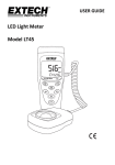
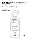
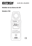
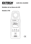
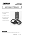
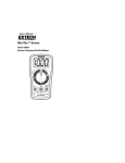
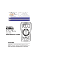
USER GUIDE White LED Light Meter Model LT40 Introduction Congratulations on your purchase of the Extech LT40 LED Light Meter that measures light from white LED light, fluorescent, metal halide, high-pressure sodium and incandescent sources. The LT40 can measure light up to 400,000 Lux (40,000 Fc). The LT40 offers an overload indication, low battery indication, Data hold, maximum/average/minimum hold (MAX/MIN), Zero adjustment, auto power off with disable function, and auto ranging features. This instrument is shipped fully tested and calibrated and, with proper use, will provide years of reliable service. Please visit our website (www.extech.com) to check for the latest version of this User Guide, Product Updates, and Customer Support. Features Overload Indication: LCD screen will show “OL” at the upper left-hand corner. Low battery Indication” Display Update Rate: 2.5 times per second. Spectral response near CIE luminous spectral efficiency ratings. Cosine Angle corrected. Conforms to JIS C 1609:1993 and CNS 5119 general class A Specifications. Measures LED white light and all visible light. Measures the intensity of illumination in Lux or foot-candles. Applications include: Warehouses, factories, office buildings, restaurants, schools, library, hospitals, photo/video, parking garages, museums, art galleries, stadiums, building security. Data hold freezes displayed reading. Maximum/Average/Minimum Memory Hold Zero adjustment. Auto power off with disable function. Auto range. ”. Safety Do not operate the meter in environments where the following are present: explosive gases (or materials), combustible gases (or materials), steam, or dust. Please replace the battery immediately when the symbol “ Do not touch the meter’s circuit board for any reason as static electricity or contamination could damage the sensitive components. For Indoor use only. This instrument was designed for pollution degree 2. Operation Altitude: Up to 2000m (7000’). 2 ” appears on the LCD. LT40-EN v1.3 9/13 Meter Description 1. Photo detector (remove protective cover to expose sensor) 2. Display (LCD) 3. Control push-buttons 4. Power Button: ON/OFF Battery compartment and tripod mount are located on rear of instrument Push-Button Description 1. Lux/Fc units selector 2. Calibration and ZERO button 3. Maximum/Average/Minimum memory button 4. Data hold button 3 LT40-EN v1.3 9/13 Operation Power ON-OFF Press and hold the Power button for at least 2 seconds and then release to power the meter. To power the meter OFF, momentarily press the Power button. Taking Measurements 1. Switch the meter ON and remove the sensor’s protective cover to expose the light sensor dome. The display should switch ON, if not check that batteries are installed and fresh. 2. The meter measures the intensity of the light (illuminance) that strikes the sensor dome in foot candles and lux units (1 fc = 10.76 lux), displaying this measured value on its LCD. 3. Position the meter and light source so that the light strikes the sensor dome straight on (perpendicular) with as little an angle as possible. 4. The meter’s display can show a value up to 3999. However, for readings that represent measurements higher than this, the meter uses x10 feature (right-most decimal point flashing). For example, to represent a measurement of 39,999 the meter will display 3999 with the right-most digit flashing. Auto Power OFF To save battery life, the meter powers down automatically after approximately 12 minutes of inactivity. Enable/Disable Auto Power Off While the meter is ON, press and hold the Power button for at least 2 seconds (and then release) to disable the Auto Power OFF utility; the Clock symbol will switch OFF. To enable the Auto Power OFF utility, repeat this process. LUX/FC Button Press the LUX/FC button to toggle between Lux and FC (foot-candles) measurement units. 4 LT40-EN v1.3 9/13 MAX/MIN Button The meter can record the maximum, minimum, and average readings as described below: 1. Momentarily press the “MAX/MIN” button and the meter will begin to track the maximum/average/minimum measurements; the “MAX” icon will display at the top of the LCD window indicating that the meter is now showing the maximum reading. The reading will not change until a higher reading is registered. 2. Press the “MAX/MIN” button again to switch from “MAX” to “AVG”, where the meter will show the average measurement value. The “AVG” icon will be displayed above the displayed value. 3. Press the “MAX/MIN” button again to change the mode from “AVG” to “MIN”, where the meter will show the minimum value measured. The “MIN” icon will be displayed. 4. Press the “MAX/MIN” button again to switch from “MIN” back to “MAX”. 5. To exit this mode, hold the “MAX/MIN” button for at least 2 seconds. The MAX/AVG/MIN icons should all be switched OFF when the unit returns to the normal operating mode. Data ‘Hold’ Button Press the HOLD button to freezes the current reading on the LCD. Press the HOLD button again to release the reading. CALIBRATION and ZERO Buttons 1000 LUX Calibration o 1. Prepare a 2856 K/1000 Lux light source and face the meter’s sensor perpendicularly toward the light source. 2. Simultaneously press and hold both the “CAL/ZERO” button and the power button for at least 2 seconds. 3. Release the buttons when “CAL” is displayed on the LCD screen. 4. Press and hold the “CAL” button for 2 more seconds, and the LT40 will power down. 5. The meter is now calibrated. ZERO Calibration 1. Ensure that the protective cover is attached to the light sensor. 2. Power the meter and the LCD should display ‘0’. 3. Momenarily press the “ZERO” button for the zero adjustment and the CAL icon will switch ON. 4. The CAL icon will switch OFF when the calibration has been completed. 5. If the protective cap is not covering the sensor when the ZEO calibration is started the LCD display will read “CAP”. In this case, please cover the sensor with the cap and restart this procedure. 5 LT40-EN v1.3 9/13 Measurement Considerations and User Tips For maximum accuracy allow the light being measured to fall directly on the sensor as perpendicular as possible with a minimal angle of incidence. When the meter is not in use please keep the protective cap in place over the light sensor. This will prolong the life of the sensor. When the meter is to be stored for long periods, please remove the batteries and store them separately. Batteries can leak and cause damage to the meter’s components. Avoid areas of high temperature and humidity when using this instrument. Battery Replacement and Maintenance Cleaning and storage 1. The white plastic sensor dome should be cleaned with a damp cloth when necessary. Use only a mild soap if needed. Do not use solvents, abrasives, or harsh detergents to clean the dome. 2. Store the meter in an area with moderate temperature and relative humidity. Battery Replacement When the battery power decreases to a critical level, the low battery symbol “ ”will appear on the LCD. Replace the 2 x 1.5V AAA batteries located in the rear battery compartment. The battery compartment slides easily downward for removal. Ensure that the compartment cover is securely fastened before using the meter. Battery Safety Reminders o Please dispose of batteries responsibly; observe local, state, national regulations. o Never dispose of batteries in a fire; batteries may explode or leak. o Never mix battery types; install new batteries of the same type. 6 LT40-EN v1.3 9/13 Specifications Display 4-digit LCD (maximum display: 3999) with low battery icon, measurement overload, and other function indicators Sensor (detector) Silicon photodiode with spectral response filter and cosine correction Ranges and Resolution Lux: 399.9, 3999, *39 999, *399 999 Foot-candles: 39.99, 399.9, 3999, *39 999 * Readings above 3999 use a x10 or x100 multiplier (1 Fc = 10.76 Lux) Auto-Range The meter automatically ranges the display Accuracy ± (3% of reading + 3 digits) up to 500 Lux ± (3%) above 500 Lux Calibrated to standard incandescent lamp 2856oK at an ambient temperature of 73oF (23oC) ±8% for other visible light sources Angle deviation from cosine characteristics 30 ○ 60 ±2% ○ ±6% 80 ○ ±25% General Specifications Sampling rate 2.5 times per second (digital display) Photo detector Silicon photo-diode with spectral response filter and cosine correction Operating conditions Temperature: 41 to 104 F (5 to 40 C); Humidity: < 80% RH Storage conditions Temperature: 14 to 140 F (-10 to 60 C); Humidity: < 70% RH Low battery indication “ ” appears on the LCD when battery voltage falls critically low LED Type White LED light can be accurately measured Power supply 2 x 1.5V ‘AAA’ batteries Battery life Approximately 200 hours Auto Power OFF Meter switches OFF after 12 minutes of inactivity Dimensions 5.2 x 1.9 x 1” (133 x 48 x 23 mm) Weight 8.8 oz. (250g) including batteries o o 7 o o LT40-EN v1.3 9/13 Appendices Typical Light Levels (1 Fc = 10.76 Lux) Lux Foot Candles 20-75 75-150 2-7 7-15 150-300 15-30 300-750 750-1,500 1,500-3,000 30-75 75-150 150-300 75-100 100-200 7-10 10-20 200-750 20-75 750-1,500 1,500-2,000 75-150 150-200 200-300 Lux Foot Candles Factories Emergency Stairs, Warehouse Exit/Entrance Passages 100-150 150-200 10-15 15-20 Packing Work 200-300 20-30 300-500 500-1,500 1,000-2,000 30-50 50-150 100-200 75-150 150-300 7-15 15-30 300-750 30-75 750-1,500 75-150 30-75 75-100 100-150 3-7 7-10 10-15 150-200 200-750 750-1,500 15-20 20-75 75-150 Visual Work: Production Line Typesetting: Inspection Work Electronic Assembly, Drafting Office Indoor Emergency Stairs Corridor Stairs Conference, Reception Room 75-150 Clerical Work 150-2000 Typing, Drafting Store 7-15 Indoors 15-20 Corridor/Stairs 20-30 Reception 300-500 500-750 750-1,500 30-50 50-75 75-150 1,500-3,000 150-300 Display Stand Elevator Show Window, Packing Table Storefront, Show Window 5,000-10,000 Home Washing Recreational Activities Drawing Room, Table Makeup Reading, Study Sewing Restaurant Corridor Stairs Entrance, Wash Room Cooking Room, Dining Table Show Window Hospital Emergency Stairs Stairs Sick Room, Warehouse Waiting Room Medical Exam Room Operating Room 500-1000 Eye Inspection Spectral Sensitivity RELATIVE SENSITIVITY (%) Peak sensitivity wavelength: 550nm Deviation from comparative standards for luminosity: JIS standard C1609-1993. LT40 WAVELENGTH (nm) 8 LT40-EN v1.3 9/13 Warranty FLIR Systems, Inc. warrants this Extech Instruments brand device to be free of defects in parts and workmanship for one year from date of shipment (a six month limited warranty applies to sensors and cables). If it should become necessary to return the instrument for service during or beyond the warranty period, contact the Customer Service Department for authorization. Visit the website www.extech.com for contact information. A Return Authorization (RA) number must be issued before any product is returned. The sender is responsible for shipping charges, freight, insurance and proper packaging to prevent damage in transit. This warranty does not apply to defects resulting from action of the user such as misuse, improper wiring, operation outside of specification, improper maintenance or repair, or unauthorized modification. FLIR Systems, Inc. specifically disclaims any implied warranties or merchantability or fitness for a specific purpose and will not be liable for any direct, indirect, incidental or consequential damages. FLIR’s total liability is limited to repair or replacement of the product. The warranty set forth above is inclusive and no other warranty, whether written or oral, is expressed or implied. Calibration, Repair, and Customer Care Services FLIR Systems, Inc. offers repair and calibration services for the Extech Instruments products we sell. NIST certification for most products is also provided. Call the Customer Service Department for information on calibration services available for this product. Annual calibrations should be performed to verify meter performance and accuracy. Technical support and general customer service is also provided, refer to the contact information provided below. Support Lines: U.S. (877) 439-8324; International: +1 (603) 324-7800 Technical Support: Option 3; E-mail: [email protected] Repair & Returns: Option 4; E-mail: [email protected] Product specifications are subject to change without notice Please visit our website for the most up-to-date information www.extech.com FLIR Commercial Systems, Inc., 9 Townsend West, Nashua, NH 03063 USA ISO 9001 Certified Copyright © 2013 FLIR Systems, Inc. All rights reserved including the right of reproduction in whole or in part in any form www.extech.com 9 LT40-EN v1.3 9/13 Garantie FLIR Systems, Inc. garantit que cet appareil Extech Instruments est exempt de défauts matériaux et de fabrication pendant un an à partir de la date d’envoi (une garantie limitée de six mois s’applique aux capteurs et aux câbles). Si le renvoi de l’appareil pour réparation devient nécessaire durant ou après la période de garantie, contactez le service client pour autorisation. Pour obtenir les coordonnées, visitez le site Web suivant : www.extech.com. Un numéro d’autorisation de retour (AR) doit être délivré avant tout retour de produit. L’expéditeur prend à sa charge les frais d’expédition, le fret, l’assurance et l’emballage correct de l’appareil afin de prévenir toute détérioration durant le transport. Cette garantie ne s’applique pas aux dommages imputables à l’utilisateur, tels que l’usage impropre ou abusif, un mauvais câblage, une utilisation non conforme aux spécifications, un entretien ou une réparation incorrecte, ou toute modification non autorisée. FLIR Systems, Inc. déclinera spécifiquement toute garantie ou qualité marchande ou aptitude à l’emploi prévu, et ne sera en aucun cas tenu responsable pour tout dommage conséquent, direct, indirect ou accidentel. La responsabilité totale de FLIR est limitée à la réparation ou au remplacement du produit. La garantie définie ci-dessus est inclusive et aucune autre garantie, écrite ou orale, n’est exprimée ou implicite. Calibrage, réparation et services après-vente FLIR Systems, Inc. offre des services de calibrage et de réparation pour les produits Extech Instruments que nous commercialisons. Nous fournissons également une certification NIST pour la plupart des produits. Contactez notre service client pour toute information sur les services de calibrage disponibles pour ce produit. Un calibrage doit être effectué chaque année pour vérifier les performances et la précision du mètre. Nous offrons également une assistance technique et un service à la clientèle. Veuillez vous reporter aux coordonnées fournies ci-dessous. Lignes d’assistance: États-Unis (877) 439-8324; international: +1 (603) 324-7800 Service d’assistance technique : Option 3 ; E-mail : [email protected] Réparations et retours : Option 4 ; E-mail : [email protected] Les spécifications produit sont sujettes à modifications sans préavis. Pour les toutes dernières informations, veuillez visiter notre site Web. www.extech.com FLIR Commercial Systems, Inc., 9 Townsend West, Nashua, NH 03063 USA Certifié ISO 9001 Copyright © 2013 FLIR Systems, Inc. Tous droits réservés, y compris la reproduction partielle ou totale sous quelque forme que ce soit. www.extech.com 10 LT40-EN v1.3 9/13 Garantía FLIR Systems, Inc., garantiza este dispositivo marca Extech Instruments para estar libre de defectos en partes o mano de obra durante un año a partir de la fecha de embarque (se aplica una garantía limitada de seis meses para cables y sensores). Si fuera necesario regresar el instrumento para servicio durante o después del periodo de garantía, llame al Departamento de Servicio a Clientes para obtener autorización. Visite www.extech.com para Información de contacto. Se debe expedir un número de Autorización de Devolución (AD) antes de regresar cualquier producto. El remitente es responsable de los gastos de embarque, flete, seguro y empaque apropiado para prevenir daños en tránsito. Esta garantía no se aplica a defectos resultantes de las acciones del usuario como el mal uso, alambrado equivocado, operación fuera de las especificaciones, mantenimiento o reparación inadecuada o modificación no autorizada. FLIR Systems, Inc., rechaza específicamente cualesquier garantías implícitas o factibilidad de comercialización o idoneidad para cualquier propósito determinado y no será responsable por cualesquier daños directos, indirectos, incidentales o consecuentes. La responsabilidad total de FLIR está limitada a la reparación o reemplazo del producto. La garantía precedente es inclusiva y no hay otra garantía ya sea escrita u oral, expresa o implícita. Servicios de calibración, reparación y atención a clientes FLIR Systems, Inc., ofrece servicios de reparación y calibración para los productos que vendemos de Extech Instruments. Además ofrecemos certificación NIST para la mayoría de los productos. Llame al Departamento de Servicio al Cliente para solicitar información de calibración para este producto. Para verificar el funcionamiento y precisión se debe realizar la calibración anual. Además se provee Soporte Técnico y servicios generales al cliente, consulte la información de contacto en seguida. Líneas de soporte: EE.UU. (877) 439-8324; Internacional: +1 (603) 324-7800 Soporte Técnico Opción 3; correo electrónico: [email protected] Reparación / Devoluciones: Opción 4; correo electrónico: [email protected] Las especificaciones del producto están sujetas a cambios sin aviso Por favor visite nuestra página en Internet para la información más actualizada www.extech.com FLIR Commercial Systems, Inc., 9 Townsend West, Nashua, NH 03063 USA Certificado ISO 9001 Copyright © 2013 FLIR Systems, Inc. Reservados todos los derechos, incluyendo el derecho de reproducción total o parcial en cualquier medio www.extech.com 11 LT40-EN v1.3 9/13