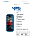
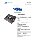
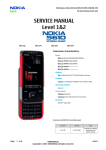
1
Horsch Elektronik AG, 9473 Gams, Switzerland, Tel. +41 81 771 61 81, FAX +41 81 771 17 47, http://www.horsch.ch e-mail: [email protected] Troubleshooting the CAN I/O bus with SMC-42. Troubleshooting sporadic errors on the CAN I/O bus is relatively difficult and time consuming. These instructions provide information on the various possible techniques that have proven useful in practice. Troubleshooting measures are suggested here. If the CAN I/O bus is functioning correctly, you will not find any error messages in the CAN statistics in the service mode. The service mode can be opened from the manual mode and the statistical data for each CAN I/O module viewed. On the occurrence of problems, the analogue signals on the CAN bus should be checked and analysed with a CRO. The SMC-42 program must be checked for correctness or modified for specific test methods. Measurements on cables, screening and terminating resistors are very important. Table of contents 1 2 3 Selecting service mode........................................................................................ 2 CAN_H and CAN_L signals on the CRO ............................................................. 3 Measuring the wiring and screening .................................................................... 4 3.1 Measuring the wiring...................................................................................... 4 3.2 CAN repeater................................................................................................. 5 3.3 Measuring the terminating resistors............................................................... 7 3.4 Measuring the screening................................................................................ 8 4 Known problems and solutions ............................................................................ 9 4.1 SMC-42 program .......................................................................................... 9 4.1.1 Baud rate declaration ............................................................................ 9 4.1.2 .LIMITS declaration ............................................................................. 10 4.1.3 .CAN_DEVICE declaration .................................................................. 10 4.1.4 CAN_ON and CAN_OFF commands .................................................. 11 4.1.5 CAN_CHECK command...................................................................... 11 4.2 System error 58 .......................................................................................... 12 4.3 Missing modules......................................................................................... 13 4.4 Malfunction or short-circuit on the output of a module ................................ 13 4.5 Short-circuit on the input of a driver............................................................ 13 4.6 Summary of the system error messages .................................................... 13 5 Filtering the CAN messages after a system error .............................................. 14 C:\Dokumente und Einstellungen\rainer_poelzl\Eigene Dateien\HE_Doku\englischOriginal\T04652_en_ 1_Teil\TEST_CAN_SMC42_en.doc Page 1 of 1 08.03.05/PH Horsch Elektronik AG, 9473 Gams, Switzerland, Tel. +41 81 771 61 81, FAX +41 81 771 17 47, 1 http://www.horsch.ch e-mail: [email protected] Selecting service mode The statistics on all CAN I/O modules that have been declared in the .CAN_DEVICE table can be opened in the service mode. You can only switch to the service mode from the manual mode. To start the service mode, press the SHIFT and 6 keys in succession. The ESC, MAN and STAT LEDs illuminate to display the service mode. To open the statistics on the CAN I/O modules, press the RIGHT (>) key. The statistics for the first module in the .CAN_DEVICE table are displayed. E.g.: SERV left,right,exit with ESC UP/DOWN 1, HIGH/LOW 10 INDEX = 0 IDENT = 4 M_ERR = 0 MESGS = 543211 REPEAT= 0 EMERG = 0 You can access the next or previous I/O module or its I/O group in steps of 1 using the UP and DOWN keys. Using the HIGH and LOW keys you can access the next or previous I/O module or its I/O group in steps of 10. The I/O group is identical to the module for the module types T0, T1 and T4. Module type T2 has 3 I/O groups because it contains 24 outputs. Each I/O group represents one I/O byte. The only difference is the higher INDEX with the same identifier ID. The INDEX is formed on the initialisation of the CAN I/O bus as per the sequence of the modules in the .CAN_DEVICE table and is incremented for each I/O group. IDENT is the identifier for the indexed I/O group. M_ERR is the maximum number of the same messages that have been repeated for the related I/O group. These error messages are sent by the I/O group if the outputs have been overloaded or short-circuited. MESGS is the total number of outgoing messages to the related I/O group since the CAN I/O bus was switched on using the CAN_ON command. REPEAT is the total number of repeated messages. EMERG is the total number of error messages for the related I/O group if the I/O module was not able to synchronise itself on the CAN I/O bus. M_ERR, REPEAT and EMERG must be equal to ZERO for correct operation! On all modules with version 1, 2 or 3 (year of manufacture 1999) REPEAT is allowed to be > 0. C:\Dokumente und Einstellungen\rainer_poelzl\Eigene Dateien\HE_Doku\englischOriginal\T04652_en_ 1_Teil\TEST_CAN_SMC42_en.doc Page 2 of 2 08.03.05/PH Horsch Elektronik AG, 9473 Gams, Switzerland, Tel. +41 81 771 61 81, FAX +41 81 771 17 47, 2 http://www.horsch.ch e-mail: [email protected] CAN_H and CAN_L signals on the CRO Figure 1. CAN bus signals on the CRO. In the figure above CAN_H (channel 1), CAN_L (channel 2) signals and their difference (calculated channel A) are shown. With a dominant signal the difference between CAN_H and CAN_L must be more than 1.5 Volt (1.5 to 3 Volt according to the line driver data sheet). With a recessive signal the difference voltage is equal to zero. The last difference signal in a CAN message is the so-called ACK signal and this is confirmed by all CAN modules on the bus. The difference voltage for the ACK signal is thus greater than the voltage for the previous signals. This example was produced with a baud rate of 125 kBit. The storage CRO used was a LeCroy with a 2.5 Gbit sampling rate. The setting for the voltage level and the triggering can be seen in the figure. C:\Dokumente und Einstellungen\rainer_poelzl\Eigene Dateien\HE_Doku\englischOriginal\T04652_en_ 1_Teil\TEST_CAN_SMC42_en.doc Page 3 of 3 08.03.05/PH Horsch Elektronik AG, 9473 Gams, Switzerland, Tel. +41 81 771 61 81, FAX +41 81 771 17 47, 3 http://www.horsch.ch e-mail: [email protected] Measuring the wiring and screening 3.1 Measuring the wiring The following measurements are made using a suitable Ohmmeter (measuring range < 200) between two CAN connectors on the ends of the cable. CAN_24V CAN_L CAN_0V CAN_H Pin 1 at the start of the cable to pin 1 at the end of the cable Pin 2 at the start of the cable to pin 2 at the end of the cable Pin 3 at the start of the cable to pin 3 at the end of the cable Pin 4 at the start of the cable to pin 4 at the end of the cable Measuring arrangement: Start of the cable 1 2 4 3 End of the cable Auxiliary wire 1 2 4 3 Ohmmeter Figure 2. Measurement of the cable resistances The resistance measured is the sum of the resistances in the connector (approx. 1030 milliohm/connector) and the cable resistances. The CAN cable used has a resistance of around 160 milliohm/m. For a 30 m long cable, around 4.8 to 5.8 Ohm will be measured on the CAN_H and CAN_L wires depending on the number of modules. It is to be noted that the CAN_H and CAN_L wires are only single wires and the CAN_0V and CAN_24V wires are duplicated; this results in the halving of the resistances of these wires. If a CAN repeater has been used, the CAN_H and CAN_L wires should be measured before and after the repeater because the repeater electrically isolates these wires. The CAN_0V and CAN_24V wires bridge the repeater. C:\Dokumente und Einstellungen\rainer_poelzl\Eigene Dateien\HE_Doku\englischOriginal\T04652_en_ 1_Teil\TEST_CAN_SMC42_en.doc Page 4 of 4 08.03.05/PH Horsch Elektronik AG, 9473 Gams, Switzerland, Tel. +41 81 771 61 81, FAX +41 81 771 17 47, http://www.horsch.ch e-mail: [email protected] 3.2 CAN repeater The electrically isolating CAN repeater transmits and amplifies the CAN signals. 7KHEXVLQSXWDQGEXVRXWSXWZLUHVDUHHDFKWHUPLQDWHGZLWKD UHVLVWRU'SUB-9 pin 2 to pin 7). The CAN_0V and CAN_24V wires and the screen are wired through directly and reservoir capacitors are arranged between the CAN_0V and CAN_24V wires. Bus input CAN_2 Bus output Connector 2 female 1 Connector 3 male 1 2 2 GND 3 4 4 Screen 5 6 3 7 8 + ) 50V 5 6 7 330nF 63V 8 +V Pin Identifier Function 2 CAN_L CAN data wire → dominant low 3 CAN_0V Ground 7 CAN_H CAN data wire → dominant high 9 CAN_24V Positive supply +24V Figure 3. CAN repeater C:\Dokumente und Einstellungen\rainer_poelzl\Eigene Dateien\HE_Doku\englischOriginal\T04652_en_ 1_Teil\TEST_CAN_SMC42_en.doc Page 5 of 5 08.03.05/PH Horsch Elektronik AG, 9473 Gams, Switzerland, Tel. +41 81 771 61 81, FAX +41 81 771 17 47, http://www.horsch.ch e-mail: [email protected] C:\Dokumente und Einstellungen\rainer_poelzl\Eigene Dateien\HE_Doku\englischOriginal\T04652_en_ 1_Teil\TEST_CAN_SMC42_en.doc Page 6 of 6 08.03.05/PH Horsch Elektronik AG, 9473 Gams, Switzerland, Tel. +41 81 771 61 81, FAX +41 81 771 17 47, http://www.horsch.ch e-mail: [email protected] 3.3 Measuring the terminating resistors Measuring arrangement: CAN plug 1 2 4 3 Ohmmeter Figure 4. Measurement of the terminating resistors End of the cable Start of the cable SMC-42 CAN repeater Terminating resistor )LJXUH WHUPLQDWLQJUHVLVWRUV 7KHWHUPLQDWLQJUHVLVWRUVDWWKHHQGVRIWKHZLUHVDUH On a measurement with a CAN repeater approx. 60 Ohm will be measured on the bus input and bus output if the CAN circuit is not open. All measurements must be made with the system switched off. C:\Dokumente und Einstellungen\rainer_poelzl\Eigene Dateien\HE_Doku\englischOriginal\T04652_en_ 1_Teil\TEST_CAN_SMC42_en.doc Page 7 of 7 08.03.05/PH Horsch Elektronik AG, 9473 Gams, Switzerland, Tel. +41 81 771 61 81, FAX +41 81 771 17 47, http://www.horsch.ch e-mail: [email protected] 3.4 Measuring the screening The error that occurs most frequently is inadequately tightened CAN connectors on the modules, or that the cable fitting on the connector for connecting the screen is not tight enough. The measured resistance between the CAN bridges from one module to another should be less than 0.4 Ohm. Figure 5. Measuring the screening If the resistances measured are higher, you should tighten the connector on the CAN cable. Good screening significantly increases the immunity of the CAN I/O bus to interference. C:\Dokumente und Einstellungen\rainer_poelzl\Eigene Dateien\HE_Doku\englischOriginal\T04652_en_ 1_Teil\TEST_CAN_SMC42_en.doc Page 8 of 8 08.03.05/PH Horsch Elektronik AG, 9473 Gams, Switzerland, Tel. +41 81 771 61 81, FAX +41 81 771 17 47, 4 http://www.horsch.ch e-mail: [email protected] Known problems and solutions For the CAN I/O bus to function correctly, several prerequisites must be met. 1) The declarations for the CAN I/O modules in the SMC-42 program must be made in the same order as they are wired. 2) The declaration for the baud rate must be the same in all modules. 3) The CAN cable must be screened, the CAN connector on every module tightened and a connector with the terminating resistors must be fitted at the end of the bus on the last module. Despite these measures defective cables, CAN I/O modules, missing terminating resistors or poor screening can cause problems. 4.1 SMC-42 program The SMC-42 program is checked by the compiler to ensure that no inputs or outputs can occur in the program that are not declared as local and extended inputs and outputs (Extension I/O) or as CAN I/O inputs and outputs. With one exception (bracketing out of the modules with the "<" operator, or the usage of the command CAN_CHECK 0) the CAN I/O modules are also continuously monitored for their presence. The most important language elements are: BIT_RATE .LIMITS .CAN_DEVICE, .END_CAN_DEVICE CAN_ON, CAN_OFF CAN_CHECK The significance of these commands can be found in the SMC-42 manual. A brief explanation follows. 4.1.1 Baud rate declaration At the start of the SMC-42 program the baud rate on the CAN I/O bus must be declared. Example: BIT_RATE 125k All modules must be pre-programmed for this baud rate. The CAN I/O bus cannot be started if this condition is not met. C:\Dokumente und Einstellungen\rainer_poelzl\Eigene Dateien\HE_Doku\englischOriginal\T04652_en_ 1_Teil\TEST_CAN_SMC42_en.doc Page 9 of 9 08.03.05/PH Horsch Elektronik AG, 9473 Gams, Switzerland, Tel. +41 81 771 61 81, FAX +41 81 771 17 47, http://www.horsch.ch e-mail: [email protected] 4.1.2 .LIMITS declaration Example: .LIMITS SMC1,I1001-1192,O1001-1192,F1001-2000,D1001-1320, CI1193-1872,CO1193-1872,T6,Z4,X5,Y6,S18,W44,J1024,G47 These include: - I O CI CO G LOCAL INPUTS LOCAL OUTPUTS CAN-BUS INPUTS CAN-BUS OUTPUTS CAN-BUS DEVICES 4.1.3 .CAN_DEVICE declaration For each individual module, the module number, the module type, the assignment of the first input and the first output must be specified in the SMC 42. Example : .CAN_DEVICE ID1,T0,I0193,O0193 ID2,T0,I0201,O0201 ID3,T1,I0209,O0209 ID4,T1,I0217,O0217 .. ID127,T4,I0281,O0281 ID63,T2,I0287,O0287 ... ID56,T2,I0409,O0409 ID8,T2,I0441,O0441 ... .END_CAN_DEVICE ;starter box Comment : ID1 is the module number 1, T0 is the module type with 8 inputs and 4 outputs, T1 is the module type with 4 inputs and 8 outputs, T2 is the module type with 24 outputs, T4 is the module type with 8 inputs and 8 outputs, I0193 is the number for the first input on module 1, O0193 is the number for the first output on module 1, If the module type is incorrectly stated, the system error 51 (CAN modul_type error ID=) is triggered with the ID number. C:\Dokumente und Einstellungen\rainer_poelzl\Eigene Dateien\HE_Doku\englischOriginal\T04652_en_ 1_Teil\TEST_CAN_SMC42_en.doc Page 10 of 10 08.03.05/PH Horsch Elektronik AG, 9473 Gams, Switzerland, Tel. +41 81 771 61 81, FAX +41 81 771 17 47, http://www.horsch.ch e-mail: [email protected] On start up or troubleshooting on the CAN I/O bus, you can bracket out the modules that are not yet connected to the bus. Example: .CAN_DEVICE ID1,T0,I0193,O0193 ID2,T0,I0201,O0201 <ID3,T1,I0209,O0209 <ID4,T1,I0217,O0217 .. <ID127,T4,I0281,O0281 <ID63,T2,I0287,O0287 ... <ID56,T2,I0409,O0409 <ID8,T2,I0441,O0441 … .END_CAN_DEVICE ;starter box The character "<" inserted at the start of the line allows the inputs and outputs to be used in the SMC-42 program without the generation of error messages by the compiler, however the bracketed out modules are not taken into account when starting up and operating the CAN bus. In this way it is possible to place individual modules in operation one after the other, or in the case of electrical problems, to switch in individual cables and modules in succession. For this reason it is strongly recommended to list the modules in the .CAN_DEVICE program block in the order in which they are actually wired. 4.1.4 CAN_ON and CAN_OFF commands These commands are used for switching on and off the CAN I/O bus. If a module is missing, the system error 59 (CAN missing modul at ID=) is triggered immediately with the ID number. 4.1.5 CAN_CHECK command Using this command the frequency of the periodic check on all CAN I/O modules is defined. Example: CAN_CHECK 5 CAN_ON On the failure of a module while the bus is in operation, the system error 53 (CAN timeout error at ID=) is triggered with the ID number. C:\Dokumente und Einstellungen\rainer_poelzl\Eigene Dateien\HE_Doku\englischOriginal\T04652_en_ 1_Teil\TEST_CAN_SMC42_en.doc Page 11 of 11 08.03.05/PH Horsch Elektronik AG, 9473 Gams, Switzerland, Tel. +41 81 771 61 81, FAX +41 81 771 17 47, 4.2 http://www.horsch.ch e-mail: [email protected] System error 58 The causes are: Defective drivers on the front panel of the SMC-42 No modules are connected Incorrect baud rate Short-circuit or open-circuit on the bus - The system error message 58 indicates the CAN I/O bus error status in which the error status of the status register in the 82527 controller is reflected. BIT Name: 7 BOff 6 Warn 5 Wake 4 RXOK 3 TXOK 2 LEC2 1 LEC1 0 LEC0 Table 1. Status register for the 82527 CAN controller The significance of the individual bits is given in detail in the data sheet on the 82527. An abbreviated version of the significance of the bits in the system register follows: BITS 7 6 5 4 3 0-2 NAME BOff Significance 0 = CAN bus is switched on 1 = CAN bus is switched off because of more than 256 errors Warn 0 = less than 96 errors on the CAN bus or none 1 = warning, more than 96 errors on the CAN bus Wake sleep mode switchover RXOK 1 = last message received without errors TXOK 1 = last message sent without errors LEC0-2 0 = no error 1 = stuff error (more than 5 bits the same in the message) 2 = shape error (incorrect format of the message received) 3 = Ack error (no CAN I/O module has received and acknowledged the message sent) 4 = bit 1 error (it was not possible to send the last message) 5 = bit 0 error (own message read incorrectly) 6 = checksum error Table 2. Bits in the status register in the 82527 CAN controller Example: p_index = 00000000 CAN_OFF STOP at system error NR: 58 CAN 8257 error status = STATUS = 43HEX 67 The STATUS 43HEX signifies that the bits 6, 1 and 0 (=3) are high. The 3 indicates an ACK error if, e.g., there is no CAN I/O module connected to the bus. C:\Dokumente und Einstellungen\rainer_poelzl\Eigene Dateien\HE_Doku\englischOriginal\T04652_en_ 1_Teil\TEST_CAN_SMC42_en.doc Page 12 of 12 08.03.05/PH Horsch Elektronik AG, 9473 Gams, Switzerland, Tel. +41 81 771 61 81, FAX +41 81 771 17 47, 4.3 http://www.horsch.ch e-mail: [email protected] Missing modules Missing or incorrectly configured modules (type) are indicated with the system errors 59 or 51 when the CAN I/O bus is started. 4.4 Malfunction or short-circuit on the output of a module If there is a short-circuit on the output of a module, or in the event of synchronisation problems on the CAN I/O bus, error signals from the individual modules are received in SMC_42, this results in system error 52 after more than 8 error messages from the same module in succession. In the case of occasional error messages, a system error is not triggered. However, the error messages are totalled for each module and appear in the error statistics. 4.5 Short-circuit on the input of a driver Such an error can only be detected with the CRO. In this case one of the two difference signals CAN_H or CAN_L is short-circuited. The consequence is an accumulation of error signals from the CAN modules that have problems with synchronisation. The module with the faulty driver is identified using a modified SMC-42 program in which, e.g., all modules except for the first two are bracketed out. The terminating resistor is connected to the second module and then the CRO image should correspond to the signal curve shown in Figure 1. Further modules are then connected electrically until the faulty module is found. Only when all other modules except the faulty module are re-connected and the CRO signal corresponds to that in Figure 1, can the faulty module be replaced with certainty. 4.6 Summary of the system error messages The SMC42 operating system generates the following system error messages. No.: 51 52 53 54 55 56 57 58 59 61 Error message CAN modul_type error ID= CAN error message at ID= CAN timeout error at ID= CAN unknown modul at ID= CAN return error at ID= CAN transmt buf overflow CAN receive buf overflow CAN 82527 error status = CAN missing modul at ID= wrong CAN identifier Significance Incorrect module type declared in CAN_DEVICE Malfunction in the CAN I/O module or short-circuit CAN I/O module no longer responds Module not declared in CAN_DEVICE Incorrect message from CAN I/O module Transmit buffer full Receive buffer full CAN I/O bus error status Missing CAN I/O module Missing CAN I/O module Table 3. Error messages C:\Dokumente und Einstellungen\rainer_poelzl\Eigene Dateien\HE_Doku\englischOriginal\T04652_en_ 1_Teil\TEST_CAN_SMC42_en.doc Page 13 of 13 08.03.05/PH Horsch Elektronik AG, 9473 Gams, Switzerland, Tel. +41 81 771 61 81, FAX +41 81 771 17 47, 5 http://www.horsch.ch e-mail: [email protected] Filtering the CAN messages after a system error In the case of a system error on the CAN I/O bus, from SMC-42 system version 8 the most recent messages can be viewed in plain text and various filters used. After the system error message, first one of the arrow keys, HIGH or LOW key is pressed to display blocks of 12 messages in steps of 1, 10 or 100. A number between 0 and 5 is then entered for the filtering. On the entry of the number 0, mode 0 is selected. Here all CAN messages are displayed in plain text as previously. If a number between 1 and 4 is selected, the ID (numbers 1 to 127) for the module to be found must be entered and confirmed with "=". Then only the CAN messages from and to the CAN I/O module with this ID are filtered. To display these messages one of the arrow keys, HIGH or LOW key must be pressed again. If the number 5 is entered then the error messages for all modules are displayed. The following table shows the allocation of the filter properties. Mode 0 1 2 3 4 5 Filter none ID, all messages ID, input messages ID, output messages ID, error messages all error messages The CAN message filter is very recommendable to ensure that modules are not replaced unnecessarily due to error messages from them as a consequence of other errors that have occurred on the CAN I/O bus. C:\Dokumente und Einstellungen\rainer_poelzl\Eigene Dateien\HE_Doku\englischOriginal\T04652_en_ 1_Teil\TEST_CAN_SMC42_en.doc Page 14 of 14 08.03.05/PH