Transcript
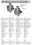
Betriebsanleitung Typ 0342, 0345, 0346 (Impuls)
Operating Instructions Types 0342, 0345, 0346 (Impulse)
Deutsch
English
Bestimmungsgemäßer Gebrauch
Der Anwender muß zur Sicherung einer einwandfreien,
gefahrenfreien Funktion und langen Lebensdauer des
Gerätes die Hinweise dieser Betriebsanleitung beachten
sowie die Einsatzbedingungen und zulässigen Daten
gemäß Datenblatt einhalten. Die Einsatzplanung und der
Betrieb des Gerätes haben nach den allgemeinen Regeln
der Technik zu erfolgen. Unbeabsichtigte Betätigungen oder
nicht zulässige Beeinträchtigungen sind durch geeignete
Maßnahmen zu verhindern.
Aufbau/ Funktion
3/2-Wege Servokolbenventil mit bistabiler Klappanker
Impulsvorsteuerung, Wirkungsweise C (Impuls auf Klemme
1 bedeutet Arbeitsanschluß entlüftet) und D (Impuls auf
Klemme 1 bedeutet Arbeitsanschluß mit Druckanschluß
verbunden), Die Handbetätigung ist nach dem Eindrücken
durch Drehen in Uhrzeigersinn arretierbar. Der
impulsgesteuerte Magnetantrieb arbeitet nach dem FlipFlop-Prinzip.
Impuls auf Klemme 2: Kern zieht an (nach Impuls
bleibt Kern-Position erhalten)
Impuls auf Klemme 1: Kern fällt ab (nach Impuls bleibt
Kern-Position erhalten)
Impulsdiagramm
magnetische
Haltekraft
Anzugsimpuls
C
Montage
Einbaulage beliebig, bevorzugt mit Magnetsystem nach
oben (verhindert Ablagerungen im Kernraum)
Rohrleitungen von Verunreinigungen säubern. Vorsteuerbohrungen im Gehäuse nicht durch Dichtungsmaterial, Rohrleitungsenden usw. verschließen. Vollen
Querschnitt der Rohrleitungen am Ein- und Ausgang des
Ventils gewährleisten.
Ventil entsprechend der am Gehäuse gekennzeichneten
Durchflußrichtung anschließen.
Befestigung des Ventils mittels der zwei Bohrungen im
Gehäuse möglich.
Zum Schutz vor Störungen Schmutzfänger benutzen.
Achtung Beschädigungsgefahr! Die mit roter Farbe
markierten Schrauben dürfen nicht betätigt werden.
Magnetspule nicht als Einschraubhebel benutzen.
Ventilgehäuse nicht verspannt einbauen.
Vakuumbetrieb mit Typ 0346
Anschluß R mit Vakuumpumpe verbinden.
Anschluß A/B an Arbeitsgeräte
Anschluß P offen zum atmosphärischen Druck, Einsatz
eines Schalldämpfers wird empfohlen.
Eine der Pumpenleistung entsprechende Nennweite
wählen.
Anzugsimpuls
Null (N) bei AC
Minus (-) bei DC
tmin
tDiff
tmin
Klemme 1
Klemme 2
3
Medium
Neutrale Gase und Flüssigkeiten, die das Messinggehäuse
und die NBR-Dichtung nicht angreifen.
Zul. Mediumstemp. 0 bis +90 °C
Max. Umgebungstemp. +55 °C
Zul. Druckbereich lt. Typschild
Construction/Function
3/2-way solenoid impulse valve, circuit function C and D
(see symbols), servoassisted. The solenoid actuator is
worked as a Flip-Flop. The manual override are operated
by push in and turn to right.
Vacuum conditions with type 0346
- Connection R is for the vacuum pump
- Connections A/B are the service ports
- Connection P is open to the atmosphere
- Recommendation: use a silencer for P!
- Select a nominal diametr for power of pump.
Impulse on terminal 1: output A pressureless
output B under pressure
Impulse on terminal 2: output A pressureless
output B under pressure
2
Klemme 3
Steckerbild
Hinweise
• Gleichzeitige Impulsgabe auf beide Spulen vermeiden (Fehlschaltungs- und Zerstörungsgefahr).
• Nur einen Verbraucher je Impulsgeber betreiben
(keine weiteren Verbraucher parallel schalten).
• Mehrpolige Schalter verwenden (galvanische
Entkopplung im ausgeschalteten Zustand).
• Vorschlag: 5 µm-Filter vor Zuluft schalten.
Störungen
Leitungsanschlüsse, Betriebsdruck und Spannungsversorgung überprüfen. Vorsteuerkanäle
durchblasen. Pumpenleistung und Nennweite prüfen.
Ersatzteile auf Anfrage.
C
D
- An short electrical impulse to the „throw coile“
(terminal 1 and 3) compensed the magnetic power
and the core falled off to the old position (before
first impulse). Attention! Never give simultaneously
impulses of both coils!
- No switch other electrical consumers (relais etc.)
parallel to the valve terminals.
- Ensure by parallel-switching of many impulse valves
the galvanical separation of nonworking coiles; otherwise are faults possible.
- Take a 5 µm-filter in front of pressure air.
Safety by assembly and working
Note that lines and valves must be unscrewed from
systems that are under pressure. Always switch off the
voltage supply before working on the system!
Take suitable measures to prevent unintentional operation
or impermissible impairment!
- Clean the pipe runs before fitting the valve!
- Recommendation: use a strainer in front of fluid!
- Observe the direction of flow!
- Can be mounted in any position, preferably with the
magnetic system at the top.
- Never use the valves as a lever when srewing in the
pipe connections!
- 2 bores in valve body may be used for attechment
- Do not turn the red marked screws!
Warning! The surface of the electromagnet can become
very hot during continuous operation.
Danger of injury!
1
Zeitachse
tmin ≥ 50 ms (min. Impulsdauer)
tDiff > 0 ms (Pause ist erforderlich)
Intended use
To ensure the device‘s unobjectionable and safe function
as well as long service life the user must follow the hints
given in this operating manual and maintain the operating
conditions and allowed data. Use and operating of the
device must be made according to the generally
recognized rules of the art. Prevent accidental operations
or unallowed interferences by suited measures.
Elektrischer Anschluß
Spannung und Stromart lt. Typschild beachten.
Spannungstoleranz ±10 %
Abwurfimpuls
Abwurfimpuls
D
tmin ≥ 50 ms (min. run time of impulse)
tDiff > 0 ms (an interval is necessary)
Fluids
Neutral gases and liquids which do not attack the brass
body or seal material NBR.
Temperature of fluids 0 to +90 °C
Max. temperature of ambient +55 °C
Pressure range as quoted on valve label.
Remarks about the impulse valves
- Electrical connection see schema.
- The impulse valve is working bistabil; in solenoid are
2 coils, which are excited through electrical impulses.
- An short impulse to the „pull coile“ (terminal 2 and 3)
pulls and holds the core in this state.
Bürkert Werke GmbH, Chr.-Bürkert-Str. 13-17, D-74653 Ingelfingen · Tel. + 49 (0)7940 - 10 91 111, Fax + 49 (0) 7940 - 10 91 448, E-mail: [email protected]
Bürkert
Company
Locations
International: Contact addresses can be found on the internet at / Die Kontaktadressen finden Sie im Internet unter: www.burkert.com
Electrical connection
Ensure supply voltage/frequncy corresponds with that on
label. The Voltage tolerance is ±10 %. Connection by cable
plug, classification IP65, cable 3 x 0,75 mm², tightening
torque for cable plug 1 Nm.
3
1
2
Schema of connection
Trouble shooting
Check port connections, voltage, operating and pilot
pressure. The valve requires no maintenance. When
operating with contaminated media, occasional cleaning
and regreasing is necessary. Check nominal diametr and
power of the pump.
Spar parts on request.
Operating Instructions 0507/02_EU-ML_00804000