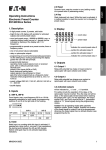
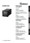
Download Operating Instructions Electronic Preset Counter Type Series 903
Transcript
2.4 Key
Static keyboard lock input. While this input is activated, it
is neither possible to reset the counter nor to change the
preset value.
Operating Instructions
Electronic Preset Counter
Type Series 903
3. Display
—— count value
—— preset value
1. Description
– 6 digit preset counter, 1 preset, add./subtr.
– bright 2-line LCD display with symbols for activated output and current preset value
– count and preset range – 999999 to 999999, over- or
underflow without count loss up to 1 decade (will be indicated by flashing of the display with 1 Hz frequency)
– programmable to operate as a preset counter, timer or
frequency meter
– relay or optocoupler output
– programming of count functions/operating parameters
via the setting keys. During programming the display
guides the user with text prompts.
– programmable features:
operating mode (output signal at zero or at preset
point, with or without automatic reset)
decimal point
polarity of the inputs (NPN or PNP)
input mode and scaling factor
output signals to be permanent or timed
gate time when programmed as a frequency meter
resolution when programmed as a timer (s, min, h or
h:min:s)
– supply voltage 230 VAC, 115 VAC, 48 VAC, 24 VAC or
11...30 VDC
– backlit display (optional)
symbol for activated output
indicator for current preset value
4. Output
Relay with potentialfree change-over contact or optocoupler with open collector and emitter.
Activated output will be indicated by
I.
For safety circuits the operation of the relay, resp. the
optocoupler may be inversed. Thus the relay coil will be
dead, resp. the optocoupler will be locked when reaching
the preset point. For that the output signal
Out 1 must be set to –l– (permanent signal) or –l–l–
(timed signal) during the programming routine.
Caution: For operating modes with automatic reset
(AddAr, SubAr) the duration of the timed signal for the
output has to be programmed, otherwise the output
signal has no defined duration (see programming).
5. Setting of the operating parameters
a. connect to supply voltage
2. Inputs
b. set microswitch „A“ (right side of the housing) to
“ON” for a short time. Display will show 1st menu
item “Mode”.
2.1 INP A, INP B
c. select required function via q
-key
Count inputs; max. count frequency 30 Hz or 10 kHz separately selectable for both inputs via programming switches C and D at the right side of the housing.
d. press P-key to store selected function/enter data
and to change over to next menu item.
OFF
ON
e. select again the required function via q
-key resp. enter
data (prescaling factor, duration of timed signal, gate
time, resolution) directly via the two arrow-keys.
A B C D
Microswitch
D
C
INP A
30 Hz
10 kHz
ON
OFF
INP B
30 Hz
10 kHz
ON
f.
OFF
After programming the last menu item (permanent or
timed signal), the programming routine will be left by
pressing the P-key, if microswitch „A“ ist set to “OFF”.
If it is still set to “ON”, the programming routine will
be passed through once again.
2.2 Gate
Static input; no counting while this input is activated.
If operated as a timer (only h, min and 0.1 min resolutions), the decimal point between the 5th and 6th
decade flashes while gate input is not activated
(operating indication).
OFF
ON
A B C D
2.3 Reset
Dynamic input; switched in parallel with the red set key
and sets the counter to zero (adding mode) or to the preset value (subtracting mode).
9
6. Setting of the operating mode
6.1 Selection of basic function
After microswitch “A” has been switched to “ON” for a
short time, one of the basic functions will be displayed
as follows:
programming
routine
Impulse Counter
programming
routine
Timer
programming
routine
Frequency Meter
Scaling factor:
0.0001…9.9999
Setting with ¤and ⁄-keys
Factor 0.0000 won’t be accepted
Caution! In operating modes Sub
and SubAr (output signal at
count value = zero) the preset value has to be integerly divisible by
the factor, otherwise the counter when resetted- will be set to the
following integer multiple of the
factor.
Decimal point
(only optical function)
0
= no decimal point
0.0 = one decimal place
0.00 = two decimal places
0.000 = three decimal places
6.2.1 Programming routine Impulse Counter
Operating mode Add:
Adding mode
Permanent signal at count value M
preset value or timed signal at count
value = preset value
Reset to zero
Permanent signal of the output,
activated at count value M preset
value in adding mode and at
count value m zero in subtracting
mode*
Operating mode Sub:
Subtracting mode
Permanent signal at count value m
zero or timed signal at count value m
zero. Reset to preset value
Permanent signal of the output,
will become passive at count
value M preset value in adding
mode and at count value m zero
in subtracting mode**
Operating mode AddAr:
Adding mode
Timed signal at count value =
preset value
Automatic reset to zero
Operating mode SubAr:
Subtracting mode
Timed signal at count value = zero
Automatic reset to preset value
Polarity of the inputs:
pospol: positive polarity (PNP)
switching to + 24 V
negpol: negative polarity (NPN)
switching to 0 V
Input modes:
E1: INP A = count input
INP B = count direction input
E2: INP A = count input adding
INP B = count input subtr.
E3: Quadrature input
INP A = count input 0°
INP B = count input 90°
E4: same as E3, but with pulse
doubling.
Each pulse edge of INP A will
be counted.
10
Timed signal of the output, will
become passive at count value =
preset value in adding mode
and at count value = zero in
subtracting mode**
Timed signal of the output,
activated at count value = preset
value in adding mode and at
count value = zero in subtracting
mode*
Duration of timed signal of the
output, can be set from 00.01 s
to 99.99 s
* Activation of relay coil resp.
optocoupler when reaching the
preset value
** Relay coil becomes dead resp.
optocoupler will be locked when
reaching the preset value.
6.2.2 Programming routine Timer
Operating mode Add:
Adding mode
Permanent signal at count value M
preset value or timed signal at count
value = preset value
Reset to zero
Operating mode Sub:
Subtracting mode
Permanent signal at count value m
zero or timed signal at count value =
zero. Reset to preset value
Operating mode AddAr:
Adding mode
Timed signal at count value = preset
value. Automatic reset to zero
Operating mode SubAr:
Subtracting mode
Timed signal at count value = zero
Automatic reset to preset value
Polarity of the inputs:
pospol: positive polarity (PNP),
switching to + 24 V
negpol: negative polarity (NPN),
switching to 0 V
Permanent signal of the output,
activated at count value M preset
value in adding mode and at count
value m zero in subtracting mode *
Permanent signal of the output will
become passive at count value M
preset value in adding mode
and at count value m zero in
subtracting mode**
Timed signal of the output, will become passive at count value =
preset value in adding mode and
at cont value = zero in subtracting
mode**
Timed signal of the output, activated at count value = preset value
in adding mode and at count value
= zero in subtracting mode*
Duration of timed signal of the
output, can be set from 00.01s to
99.99 s.
* Activation of relay coil resp. optocoupler when reaching the preset
value
** Relay coil becomes dead resp.
optocoupler will be locked when
reaching the preset value.
Unit of time:
Timing in s; 0.1 s; 0.01 s or 0.001 s*
Timing in min; 0.1 min; 0.01 min*
or 0.001 min*
Timing in h; 0.1 h; 0.01 h or 0.001 h*
* depending on position of the
decimal point
Timing in h: min: s
Decimal point (resolution):
0
= no decimal point
0.0 = one decimal place
0.00 = two decimal places
0.000 = three decimal places
11
6.2.3 Programming routine Frequency Meter
Gate time = within this period the
incoming pulses will be counted and
displayed.
Programmable range from 00.01 s
to 99.99 s
Setting with ¤and ⁄-keys
00.00 won’t be accepted
Polarity of the inputs:
pospol: positive polarity (PNP),
switching ot +24 V
negpol: negative polarity (NPN),
switching to 0 V
Permanent signal of the output,
activated at count value M preset
value*
Permanent signal of the output, will
become passive at count value M
preset value**
Timed signal of the output, will
become passive at count value =
preset value**
Timed signal of the output, activated
at count value = preset value*
Input modes:
E1: INP A = count input
INP B = count direction input
E2: INP A = count input adding
INP B = count input subtr.
E3: Quadrature input
INP A = count input 0°
INP B = count input 90°
E4: same as E3, but with pulse
doubling.
Each pulse edge of INP A will
be counted.
Scaling factor:
0.0001…9.9999
Setting with ¤and ⁄-keys
Factor 0.0000 won’t be accepted
Decimal point
(only optical function):
0
= no decimal point
0.0 = one decimal place
0.00 = two decimal places
0.000 = three decimal places
12
Duration of timed signal of the
output, can be set from 00.01 s to
99.99 s
* Activation of relay coil resp.
optocoupler when reaching the
preset value
** Relay coil becomes dead resp.
optocoupler will be locked when
reaching the preset value.
7. Programming of the Preset Value:
8. Examples for application connections:
After pressing one of the arrow keys, the leading zero
blanking will be suppressed for approx. 4 seconds and
the least significant digit of the preset value flashes with
a frequency of 1 Hz.
The value of the flashing digit can be increased by using
the ⁄-key. With the ¤ key it will be changed to the next digit. If no key is pressed for 4 seconds, the
leading zero blanking will be activated automatically
again.
In operating mode Impulse Counter and Frequency Meter the new value will be taken over now.
Count pulses from contact closure
(programmed polarity PNP)
Setting of the 6th decade
7.1 Setting of the sign
Select the sign by using the ¤ key. The sign will start to
flash now and can be assigned to the preset value resp.
eliminated by using the ⁄-key.
If no key is pressed for 4 seconds, the leading zero
blanking will be activated automatically again. Preset
value and count value are displayed now with the
corresponding sign.
Caution! In case of automatic reset no negative values
are to be set for the preset value.
Count pulses from a light barrier
Count pulses from a shaft encoder
13
9. Connections
10. Technical Data
Supply voltage:
90…260 VAC, 48 VAC, 24 VAC,
50/60 Hz, ±10 %,
max. 4 VA
or 11…30 VDC, max. 0.1 A
Display:
6 digit, 2-line 7 segment LCD display
with sign
count value 9 mm high characters
preset value 7 mm high characters
symbols for displayed preset and closed output contact
Polarity of input signals:
programmable, all inputs in common
Input sensitivity:
approx. 10 kOhm
9.1 Plug connection X1
Terminal
No.
1
2
3
4
5
6
7
AC version
DC version
without connection
without connection
relay output common contact (C)
optocoupler output emitter
relay output normally open contact (NO)
relay output normally closed contact (NC)
optocoupler output collector
90…260 VAC/
11…30 VDC
48 VAC/24 VAC
operating voltage
90…260 VAC
0 VDC (GND)
48 VAC/24 VAC
Caution! For settings –l– and –l–l– (inverted operation of
relay or optocoupler) the connections of terminal 4 and 5
change as follows:
Terminal AC- and DC versions
No.
4
relay output normally closed contact (NC)
5
relay output normally open contact (NO)
9.2 Plug connection X2
Terminal Designation Function
No.
230 VAC/115 VAC
48 VAC/24 VAC
version
1
+ 24 VDC Transmitter voltage
2
GND
0 VDC reference
voltage
3
INP A
count input A
4
INP B
count input B
5
RESET
reset input
6
GATE
gate input
7
KEY
keyboard lock input
Function
11…30 VDC
version
—
—
Count frequency:
via DIL switches separately selectable for
INP A and INP B
30 Hz
10 kHz (7 kHz for input modes E3 and E4,
quadrature inputs)
in case of automatic reset 900 Hz
without count losses (500 Hz for input mode
E4)
Min. pulse length of the control inputs:
5 ms
Input sensitivity:
For AC supply voltages
Log “0”: 0… 4 VDC
Log “1”: 12…30 VDC
For DC supply voltage Ub
Log “0”: 0…0.2 x Ub
Log “1”: 0.6 x Ub…30 VDC
Pulse shape: variable (Schmitt Trigger characteristic)
Output:
Relay with potentialfree make or break
contact
switching voltage max.
250 VAC / 300 VDC
switching current max. 3 A
switching current for DC min. 30 mA
switching performance max. 50 W for DC
and max. 2000 VA for AC
or
optocoupler with open collector and emitter
switching performance: 30 VDC/15 mA
Ucesat at Ic = 15 mA: max. 2.0 V
Ucesat at Ic = 5 mA: max. 0.4 V
Responding time of outputs:
Relais:
approx. 6 ms
Optocoupler: approx. 1 ms
Data retention:
min. 10 years or 106 memory cycles
Transmitter voltage:
24 VDC –40 % / +15 %, 80 mA
unstabilized for 24 and 48 VAC-versions
24 VDC –40 % / +15 %, 100 mA
unstabilized for 90…260 VAC-versions
14
Fuse protection:
recommended fuse
for DC:
0.125 AT
for 90…260 VAC: 0.05 AT
for 48 VAC:
0.2 AT
for 24 VAC:
0.4 AT
Noise immunity:
EN 55011 class B and EN 50082-2
with shielded data inputs
Ambient temperature:
0…50°C
Storage temperature:
–25°C…+70°C
Weight:
approx. 240 g (AC-version with relay)
Protection: IP 65 (front)
Colour of housing:
black
Cleaning:
The front of the unit is only to be cleaned
with a soft and wet (water !) cloth.
11. Delivery includes
– Counter 903
– Screw terminal plug 7 poles, reference grid 5.08 mm
– Screw terminal plug 7 poles, reference grid 3.81 mm
– Bezel for screw mount, panel cut-out 50 x 50 mm
– Bezel for clip mount, panel cut-out 50 x 50 mm
– Panel mounting clip
12. Ordering Code
6.903.010.000
Option:
00 = without
10 = backlit LCD
Supply voltage:
0 = 90…260 VAC
3 = 11…30 VDC
Output:
0 = Relais
1 = Optocoupler
15


