1
Pressing for Excellence
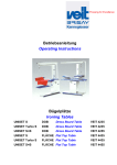
Betriebsanleitung
Operating Instructions
VEIT 4460
Varioline S
Varioline S & B
TD4460_i20090429
VEIT GmbH
Justus-von-Liebig-Str. 15
D - 86899 Landsberg am Lech
Germany
Phone +49 (81 91) 479 0
Fax
+49 (81 91) 479 149
www.veit-group.com
Service Hotline
Germany:
Europe:
America:
Asia:
+49 (81 91) 479 133
+49 (81 91) 479 252
+1 (770) 868 8060
+852 2111 9795
Ersatzteile/Spare parts
Vertrieb/Sales
+49 (8191) 479 176
Vertrieb Textilpflege/ +49 (8191) 479 129
Sales Textile care
TD4460_i20090429
Varioline
VEIT 4460
Inhaltsverzeichnis / Table of Contents:
1 Übersichtsdarstellung / Survey Drawing
4
2 Warnhinweise / Warnings
5
3 Technische Daten CR2 / Technical Data CR2
6
4 Allgemeine Informationen / General Information
8
4.1 Gerät aufbauen / Assembly
4.2 Elektrischer Anschluss / Power Supply
4.3 Einschalten / Ausschalten / On / Off
4.4 Transport / Transportation
4.5 Höhenverstellung / Height Adjustment
8
8
8
8
8
5 Betrieb / Operation
9
6 Wartung und Pflege / Maintenance and Service
10
7 Störungen und ihre Beseitigung / Malfunctions and
Troubleshooting
11
8 Aufbauanleitung / Assembly Instructions
12
8.1 Universal-Bügelplatz Spitze rechts / Universal Ironing Tables Point Right
8.2 DOB – Bügelplatz Spitze links / DOB Ironing Tables Point Left
8.3 Schutz für Kamin u. Schwenkarm / Protection for Chimney a. Swivel Arm
8.4 Stützlager / Swivelarm Bracket
15
16
17
17
9 Ersatzteile / Spare Parts
19
9.1 Zeichnung / Drawing
9.2 Ersatzteilliste / Spare Parts List
19
20
10 Schaltplan / Circuit Diagram
22
11 EG-Konformitätserklärung / EC Declaration of
conformity
24
29.04.2009
3
Varioline
VEIT 4460
1 Übersichtsdarstellung / Survey Drawing
Büglerschwebe mit:
- Laufschiene
- Rollen mit Balancer für Bügler
- Arbeitsplatzbeleuchtung
Iron gantry, including:
- guide rail
- balancer for iron
- workplace lighting
Abwindkamin
Air vent chimney
Elektro-Box mit:
- Gerätehauptschalter
- Steuerungsplatine
- Leistungsschütz für Gebläsemotor
- Sicherung
- Steckdose und Anschlußkabel
electronic box, including:
- main switch
- PC-board
- contactor for fan motor
- fuse
- socket and power cable
Höhenverstellung mit:
- Kreuzgriffschrauben (beidseitig)
- Gasdruckfeder
height adjustment, including:
- both side star grip
- gas pressure spring
Transportrollen
Transportation wheels
Standfuss mit Fußschaltleiste
- horizontale Fußschaltleiste für Saugen
- vertikale Fußschaltleiste für Blasen
Fangwanne
Spilltray
Support Stand with kickerplate
- horizontal kickerplate for suction
- vertical kickerplate for blowing
Gummifuß verstellbar
Adjustable rubber foot
Bügelfläche DOB
Ironing surface dress board
Schwenkarmanlage bestehend aus:
- Schwenkarm
- Bügelform
- Stützlager
swivel arm, including:
- swivel arm
- ironing form
- swivel arm bracket
29.04.2009
4
Varioline
VEIT 4460
2 Warnhinweise / Warnings
Bestimmungsgemäßer Gebrauch: Der Bügeltisch dient
Intented use of machine: The Varioset is designed only for
ausschließlich dem Bügeln mit und ohne Dampf.
ironing with and without steam. Especially spot removing
Insbesondere ist die Fleckentfernung mit Lösungsmitteln
with solvents or other inflammable or explosive substances
oder anderen brennbaren oder explosiven Stoffen nicht
are prohibited.
zulässig.
1. Bügeltisch nur in vollständig montiertem Zustand in
1. The ironing table should only be operated when it is
Betrieb nehmen!
completely assembled!
(Standfuß, Bügelfläche, Abwindkamin)
(support stand, ironing surface, air-vent-chimney).
2. Das Gerät darf nur mit der Spannung und Stromart
betrieben werden, die auf dem Typenschild angegeben
2. Only use the voltage and type of current shown on the
machine plate.
sind.
3. Gerät vor jeder Inbetriebnahme auf sichtbare Schäden
3. Before each usage of the unit check for damages. If
prüfen. Sind Schäden vorhanden, sofort
there are damages unit must be repared. Do not start
Reparatur/Instandsetzung veranlassen. Gerät NICHT in
unit.
Betrieb nehmen!
4. Störungen an der elektrischen Einrichtung dürfen nur
durch zugelassene Fachkräfte behoben werden.
5. Vor Öffnen des Gerätes Netzstecker ziehen und
4. Electrical faults must only be repaired by authorized
personnel.
5. Disconnect the power supply and the connection cable
Verbindungskabel zum Dampferzeuger oder Kondensor
to the steam generator or condenser before opening the
trennen.
machine.
6. Der Netzanschluss muss betreiberseitig abgesichert
6. The mains supply must be secured by the customer.
sein! Vorschriften örtlicher Elektrizitätsgesellschaften
Take note of the regulations of the local electric
sind zu beachten.
suppliers.
7. Das Gerät ist mit einem Stecker ausgestattet. Dieser
7. The unit is supplied with a plug. This plug is the
Strecker ist die Netz-Trenneinrichtung. Der Stecker
electrical disconnection. The plug must be easily
muss frei zugänglich sein und darf nicht verbaut
accessible and must not be covered by any component.
werden. Ein Direktanschluss ohne Stecker ist nicht
Do not connect without a plug.
zulässig.
8. Im Gefahrenfall das Gerät durch Betätigen der NetzTrenneinrichtung (ziehen des Netzsteckers) stillsetzen.
9. Die Netzanschlussleitung muss so verlegt sein, dass ein
8. In an emergency, the machine can be stopped by pulling
out the mains plug or by operating the mains switch.
9. Mains supply cable must be laid in such a way that
größtmöglicher Schutz gegen eine mechanische
maximum protection against mechanical damage is
Beschädigung gegeben ist und dass die Leitung keine
ensured and that no one will trip over the cable
Stolperschwelle darstellt
10. Es ist darauf zu achten, dass die Netzanschlußleitung
nicht mit heißen Dampf-/Kondensatleitungen in
10. Care must be taken that the mains supply has no
contact with steam-/condensate pipeline.
Berührung kommt.
11. Es dürfen nur von Veit zugelassene Ersatz- und
11. Use only Veit spare parts and accessories.
Zubehörteile verwendet werden.
12. Beim Verschieben des Tisches oder bei
Höhenverstellung darauf achten, dass das
12. Take care not to damage the connection cable when
moving the table or adjusting the height.
Anschlusskabel nicht eingeklemmt oder beschädigt
wird.
29.04.2009
5
Varioline
VEIT 4460
3 Technische Daten CR2 / Technical Data CR2
29.04.2009
6
Varioline
VEIT 4460
Elektrischer Anschluss:
V
siehe Typenschild
Hz
siehe Typenschild
kW
siehe Typenschild
A
siehe Typenschild
Netzseitige Absicherung
16 A, Typ B
Anschlusskabel
Länge: 3,7 m mit Stecker
Luftmenge max.
1000 m3/h
Gewicht
115 kg
Bügelfläche
500 x 1388 mm
Schalldruckpegel (1,6 m Höhe; 0,5 m Abstand von
Vorderkante)
DOB CR 2: Saugen = 73,5 dB (A), Blasen = 76,5 dB (A)
Electrical connection
V
see type label
Hz
see type label
kW
see type label
A
see type label
Fuse protection
16 A, Type B
Connection cable
Length: 3,7 m with plug
Exhaust air volume max.
1000 m3/h
weight
115 kg
Ironing buck
500 x 1388 mm
Sound pressure level (height 1.6 m; distance 0.5 m from the
front of the unit)
DOB CR2: Suction = 73,5 dB (A), Blowing = 76,5 dB (A)
29.04.2009
7
Varioline
VEIT 4460
4 Allgemeine Informationen / General Information
4.1 Gerät aufbauen / Assembly
Für den Aufbau der verschiedenen Geräte und
Zusatzeinrichtungen stehen je nach Bedarf entsprechende
Aufbau-Anleitungen zur Verfügung. (Entnehmen Sie diese bitte
den Einzel-Aufbauanleitungen in Abschnitt 8).
For assembly of different units and additional modules please
see special assembly instructions (section 8).
ACHTUNG:
Attention:
Das Gerät darf nur in Betrieb genommen werden, wenn alle
Komponenten ordnungsgemäß zusammengefügt wurden !
Do not start unit before all components have been
assembled correctly!
4.2 Elektrischer Anschluss / Power Supply
Gerät darf nur mit der Spannung und Stromart sowie nur mit der
Frequenz betrieben werden, welche in der Betriebsanleitung
bzw. auf dem Typenschild angegeben ist
Run unit only with voltage and type of current indicated in
Operating Instructions or shown on type label.
Der Netzanschluss muss betreiberseitig abgesichert sein.
Vorschriften örtlicher Verteilungsnetzbetreiber (VNB) sind zu
beachten.
Angaben zur Absicherung sind den elektr. Anschlussdaten bzw.
dem Schaltplan zu entnehmen
The mains supply is the responsibility of the customer. Follow
regulations of the local electric suppliers
Das Gerät besitzt eine fertige Netzanschlussleitung mit einem
Schuko-Stecker. Dieser Stecker ist zugleich die NetzTrenneinrichtung
Unit has a power connection with a safety plug. This plug is also
the mains supply break.
ACHTUNG:
ATTENTION:
Der Stecker muss frei zugänglich bleiben und darf nicht
verbaut werden. Ein Direktanschluss ohne Stecker ist nicht
zulässig !
This plug must be easily accessible and must not be
covered by any component. Direct supply without plug is
not admitted!
You will find further information in the electrical data or in the
circuit diagram.
Die Netzanschlussleitung muss so verlegt werden, dass sie nicht Care must be taken that the mains supply has no contact with
mit heißen Dampfleitungen in Berührung kommen kann und
steam pipe and is protected against mechanical danger!
möglichst geschützt ist gegen mechanische Gefährdungen!
4.3 Einschalten / Ausschalten / On / Off
Mit dem Geräteschalter (hinten am Grundgerät) wird der
Bügeltisch eingeschaltet => Schalter leuchtet.
Unit is started with main switch (at the rear of the base unit) =>
switch is illuminated.
4.4 Transport / Transportation
Das Gerät kann nach Ankippen auf die hinteren Transportrollen
Base module can easily be moved by tilting unit over rear
leicht bewegt werden. Für Flächen- und Universal-Bügelplätze
transportation wheels.Transport cart E 29 is used for flat top
kann der Transportwagen E 29 eingesetzt werden.
ironing tables.
4.5 Höhenverstellung / Height Adjustment
Durch Lösen der beiden seitlichen Sterngriffe lässt sich das
Gerät auf die gewünschte Höhe einstellen. Dabei darauf achten,
dass das Anschlusskabel nicht gequetscht wird.
29.04.2009
Release the two star-grip bolts to adjust height. Take care that
the connection cable is not damaged.
8
Varioline
VEIT 4460
5 Betrieb / Operation
D
A
E*
B* / C
Bügeltisch mit Netzschalter [A] einschalten. Je nach
betätigtem Fußschalter kann man Blasen [B]* bzw.
Saugen [C].
Switch on the ironing table using the main switch [A]. Use
the foot switch for blowing [B]* or for suction [C].
Der Luftstrom wird auf den Schwenkarm umgelenkt,
sobald dieser über die Bügelfläche geschwenkt wird.
The air flow switches to the swivel arm, as soon as it is
moved over the ironing surface.
Die Saug-Dosierung der Luftmenge ist über den am Kamin
angebrachten Drehschieber [D] möglich.
The air quantity for suction can be adjusted with the rotary
slide valve [D] at the chimney.
Die Blas-Dosierung der Luftmenge ist über den am
Grundgerät angebrachten Drehschieber [E] möglich*.
The air quantity for blowing can be adjusted with the rotary
slide valve [E] on the base unit*.
* gilt nur für Varioline S&B
* only valid for Varioline S&B
29.04.2009
9
Varioline
VEIT 4460
6 Wartung und Pflege / Maintenance and Service
ca. alle 40 Betriebsstunden
oder nach 4 Wochen
Schaumstoff und Kunstfaserbezug waschen
bei 30° in der Waschmaschine oder
Handwäsche
ca. alle 40 Betriebsstunden
oder nach 4 Wochen
Das weiße Gewirke überprüfen und
gegebenenfalls reinigen
mit Pressluft ausblasen, ggf. in der
Waschmaschine waschen
ca. 1 x jährlich
Gebläselüfterrad reinigen
je nach Verschmutzung, Lamellen mit
Pinsel oder Pressluft reinigen. Zum
Lüfterrad-Ausbau siehe
Ersatzteilzeichnung
After approx. 40 working hours
or after 4 weeks
Clean the foam layer and the synthetic cover
In the washing machine at 30°C or with
warm water by hand
After approx. 40 working hours
or after 4 weeks
Check the Prefitt cover and the silicon-layer.
Clean them, if necessary
Use a hard brush and compressed air
approx. once a year
Clean the impeller
Clean the blades with a brush or
compressed air depending on soiling. For
removing the impeller, please see spare
part drawing
Wartungsanweisung
Gebläselüfterrad reinigen
Achtung !
Netzstecker ziehen- Erdungskabel, das zum Abluftkamin
führt, abziehen.
- Seitliche Blechschrauben lösen und
Elektrik-Box nach unten ausschwenken.
- Lüfterrad mit Pinsel, Pressluft oder
Staubsauger reinigen.
Maintenance instructions
Cleaning of the impeller
Caution!
Disconnect power supply
- Disconnect ground wire which leads to
air-vent chimney
- Remove screws at the side and swing
down the E-Box.
- Clean the blades with a brush,
compressed air or a vacuum cleaner.
29.04.2009
10
Varioline
VEIT 4460
7 Störungen und ihre Beseitigung / Malfunctions and Troubleshooting
Störung
Ursache
Abhilfe
Schlechte Absaugung bzw.
Blaswirkung
Verschmutzter Bezug
Bezug reinigen bzw. erneuern
Keine Absaugung bzw.
Blaswirkung
Gebläsemotor läuft nicht
1. Thermoschutz im Motor hat durch Überlastung
ausgeschaltet; nach Abkühlung (ca. 15 Min.) wieder
betriebsbereit
2. Fußschalter prüfen
3. E-Box lösen, Schütz auf Platine prüfen
Gebläsemotor läuft laut
Lüfterrad verschmutzt und daher
Unwucht
Lüfterrad reinigen
Problem
Cause
Solution
Insufficient suction or blowing
Dirty cover
Clean or replace the cover
No suction or blowing
Fan does not run
1.
Fan motor runs loudly
29.04.2009
Impeller dirty and therefore
unbalanced
(siehe Kap. Wartung und Pflege)
Thermal protection in the motor has switched off
because of overload. Ready for operation after
cooling down (approx. 15 min.)
2.
Check the foot switch
3.
Unscrew the e-box, check the contactor on the
PC-board
Clean the impeller
(see section “Maintenance and Service”)
11
Varioline
VEIT 4460
8 Aufbauanleitung / Assembly Instructions
Bitte beachten Sie auch die mit den Ziffern
gekennzeichneten Positionen in den folgenden
Übersichtsdarstellungen, ebenso den Zusatz Seite 13 u. 14.
Please also note the numbered positions in the following
description as well as added pages 13 and 14.
1
Grundgerät aufstellen.
1
Mount the base module.
2
Stabilisierungsprofil aus dem Rechteckrohr des
Grundrahmens ziehen. Kunststoffkappe auf der
entsprechenden Seite des Standfußes abnehmen und mit
dem Stabilisierungsprofil Grundrahmen und Standfuß
verschrauben. Danach Standfuß mit Schrauben M 8x60
am Grundgerät befestigen.
2
Pull the stabilizing profile out of the rectangular tube of the
base frame. Remove the plastic cap on the corresponding
side of the support stand and screw the base frame and
the support stand on with the stabilizing profile. Then
fasten the support stand by screws M 8x60 at the base
module.
3
Trägerplatte oben von dem Grundgerät abschrauben.
3
Unscrew the supporting plate at the top of the base
module.
4
Das Stützlager mit Distanzplatte am Grundgerät
anschrauben .
4
Fasten the swivel arm bracket with the distance plate at
the base module with screws.
5
Distanzplatte
5
Connect the micro switch cable to the base module.
6
Kamin auf das Grundgerät montieren.
6
Mount the chimney on the base module.
7
Schwenkarmrohr montieren (siehe Zusatz S. 14).
7
Assemble the swivelarm tube (see page 14).
8
Arbeitsplatzbeleuchtung montieren (s. Zusatz S. 13, 14).
8
Mount the workplace illumination (see page 13, 14).
9
Bügelfläche mit der Umschaltabdeckung verschrauben,
auf das Grundgerät aufsetzen und Trägerplatte mit den
Spezialschrauben anschrauben.
9
Fasten the ironing surface on the switch-cover with
screws, put it on the base module and fasten the
supporting plate with the special screws.
10
Stützfuß am Standfuß anschrauben, Fangwanne mit
Strebe verschrauben und mit den Flügelschrauben
festklemmen.
10
Screw the leg support on the support stand, fasten the
spilltray on the support and clamp them with the wing
screws.
11
Bügeleisenabsteller montieren (nur bei Spitze rechts).
11
Mount the iron rest (at point right only).
12
Fußschaltleiste in passende Position am Standfuß
einstecken und das Kabel mit den selbstklebenden Clips
befestigen. Kabelstecker an der Unterseite der E - Box
anschließen.
12
Push the kicker plate in the suitable position at the support
stand and fix the cable by the self-adhesive clips. Connect
the cable of the display to the plug at the bottom of the
electronic box.
13
Bezug auf der Bügelfläche befestigen.
13
Fix the cover on the ironing surface.
14
Bügelplatz am endgültigen Standort mit Hilfe der
höhenverstellbaren Gummifüße an Bodenunebenheiten
anpassen und die Kontermuttern der Fußverstellung
anziehen.
14
Adjust the ironing table at the final workplace to any
unevenness of the floor by means of the height-adjustable
rubber feet and fasten the counter nuts of the foot
adjustment.
15
Zur Höhenverstellung beide Sterngriffe am Grundgerät
lösen.
15
Unscrew the two star grips at the base module to adjust
the height.
16
Schwenkarm mit Bügelform montieren.
16
Assemble the swivelarm with ironing buck.
29.04.2009
12
Varioline
VEIT 4460
Zusatz:
Anbau der Beleuchtung und Schwenkarmrohr / Addition:
Assembly of illumination and swivelarm tube
91101100130-Schraube / Screw
9130111210-Scheibe / Disc
9130310420-Federring / Snap ring
9120110230-Mutter / Screw nut
4447015450-Distanzhülse / Distance tube
9130111210-Scheibe / Disc
91101100130-Schraube / Screw
29.04.2009
13
Varioline
VEIT 4460
Anschlußkabel der Lampe wie dargestellt durch
Abwindkamin führen, um eine Kollision mit der
Drosselklappe zu vermeiden.
Lead the connecting cable of the lamp as shown to
avoid collision with the throttle plate.
Schwenkarmrohr kann beidseitig montiert werden
Swivelarm tube can be installed on both sides
9110110210-Schraube / Screw
9130111210-Scheibe / Disc
29.04.2009
14
Varioline
VEIT 4460
8.1 Universal – Bügelplatz Spitze rechts / Universal Ironing Tables Point Right
29.04.2009
15
Varioline
VEIT 4460
8.2 DOB-Bügelplatz Spitze links / Dress Board Ironing Tables Point Left
29.04.2009
16
Varioline
VEIT 4460
8.3 Schutz für Kamin und Schwenkarm / Protection for Chimney and Swivel Arm
Schutz für Kamin und
Schwenkarm zum Aufkleben
Artikel-Nummer: 249 770 075 0
Schutzmaterial Kamin:
340x200mm
Schutzmaterial Schwenkarm:
300x50x1mm
Protection air-vent-chimney and swivelarm to
stick on.
Article-number: 249 770 075 0
Protective covering air-vent-chimney:
340x200 mm
Protective covering swivelarm:
300x50x1 mm
8.4 Stützlager / Swivelarm Bracket
Stützlager
Swivelarm Bracket
Schwenkarme für Varioline
Swivelarms for Varioline
29.04.2009
17
Varioline
VEIT 4460
8.4
Schrauben an Umschaltnase lösen und Schwenkarm in
Arbeitsposition bringen.
Release screws at switch cam and direct swivel arm into
working position.
Umschaltnase einstellen und Schrauben festziehen.
Set switch cam to swivel arm shifter and fasten screws.
Wenn Schwenkarm in Arbeitsposition eingeschwenkt wird
muss die Umschaltnase die Klappenmechanik eindrücken
When the swivel arm is in working position, the swivel
arm shifter has to be pushed.
29.04.2009
18
Varioline
VEIT 4460
9 Ersatzteile / Spare Parts
9.1 Zeichnung / Drawing
18
18a
18e
18b
18c/18d
29.04.2009
19
Varioline
VEIT 4460
9.2 Ersatzteilliste / Spare Parts List
9.2.1 Allgemein
Pos.
Artikel-Nummer
Benennung
Designation
Article Number
01
479 145 009 0
02
02b
444 402 020 0
Geräteschalter mit Spritzschutz
Main switch with splash guard
=> Siehe Schaltplan
=> see circuit diagram
Kleinteilesatz / Schaltung bestehend aus:
Abstandsbolzen, Distanzhülse 7,5 + 13,5 lang,
Mutter M3, Federring A3, und Zugentlastung
Set of small parts / circuit, consisting of: distance
bolt, distance bushing 7,5 + 13,5 long, nut M3,
spring washer A3 and strain relief
06
444 302 013 0
Anschlusskabel mit Stecker 4,2m
Connection cable with plug 4,2m
09
114 836
Frontverkleidung
Front cover
18
120 670
Abdeckung Umschaltung
Cover switch
18a
916 021 028 0
Druckfeder
Pressure spring
18b
914 153 021 0
Bundbuchse ∅8
Flange sleeve ∅8
18c
444 301 017 0
Federstahldraht
Spring steel wire
18d
915 011 015 0
Schnellbefestiger ST DM 4 mm
Quick fastener ST DM 4 mm
18e
115 054
Umschaltklappe
Switch flap
20
123 492
Abwindkamin Varioline BT
Air-vent chimney Varioline BT
22
114 873
Dämmplatte Abwindkamin
Insulating board air-vent chimney
23
114 870
Dämmplatte selbstklebend Deckel Abwindkamin
Insulating board self-adhes. top air-vent-chimney
26
444 702 619 0
Dämmplattensatz beidseitig VS
Insulating board kit
Shock-proof socket with flap
27
440 000 139 0
Schuko-Einbaudose mit Klappe
29
916 021 014 0
Gasdruckfeder 90kg
Gas pressure spring 90 kg
30/31
444 402 023 0
Klemmeinheit für Höhenverstellung bestehend
aus: Kreuzgriffschraube (2x) und Scheibe (2x)
Clamping unit for height-adjustment, consisting
of: star handle screw (2x) and washer (2x)
32
444 701 045 0
Laufrad 50x20 mit Gleitlager
Wheel 50x20 with ball bearing
33
444 132 510 0
Gummifuß kpl.
Rubber foot cpl.
--
114 849
Kabel Fußschaltleiste
Cable kicker plate
36
929 065 041 0
Schalter Fußschaltleiste (1 Stück)
Switch kicker plate(1 piece)
--
444 702 003 0
Feder (5 Stück) - Schaltleiste S / Fußschaltleiste
+B
Spring (5 pieces) - kicker plate S / kicker plate
S+B
114 887
Bezug kpl. bestehend aus:
Complete cover consists of:
300 009 002 0
1 St. Spannfeder mit Klip 24cm
1p. tension spring with clip 24cm
300 009 003 0
1 St. Spannfeder mit Klip 21cm
1p. tension spring with clip 21cm
300 009 004 0
2 St. Spannfedern mit Klip 16cm
2p. tension springs with clip 16cm
342 361 008 0
1 St. Bezug Kunstf./BFL DOB BR.CR/VS
1p. cover synthetic fibre BFL DOB BR.CR/VS
324 361 013 0
1 St. Schaumstoff /BFL DOB BR.CR/VS
1p. foam BFL DOB BR.CR/VS
114 888
1 St.Abstandsgew. Weiss VS2008 CR2
1p.distance thread white VS2008 CR2
Version 50Hz
07
929 095 042 0
Motor 230V/50 Hz
Motor 230V/50 Hz
08
444 133 002 0
Gebläserad 180x92 linksdrehend
Impeller 180x92 turning counter-clockwise
Version 60Hz
07
929 095 043 0
Motor 550/700W 50/60HZ
Motor 550/700W 50/60HZ
08
444 703 003 0
Gebläserad 180x74 linksdrehend
Impeller 180x74 turning dextrorotatory
29.04.2009
20
Varioline
VEIT 4460
9.2.2 Varioline S
Pos.
Artikel-Nummer
Benennung
Designation
Article Number
05
116 309
Relaisplatine 230V/24V VL S
Relay PC-board 230V/24V VL S
10
119 583
Klappenkasten VL S
Flap box VL S
--
123 543
Schaltleiste ET kpl. VL S
Kicker plate cpl. VLS
34
540 201 560 L
SCHALTLEISTE STAND. SAUG BLAU
Kicker plate suction
13
119 587
Abdeckblech Klappenkasten VL S
Metal cover flap box VLS
15
123 562
Verschlussbl. hinten Klappenk.
Rear closing sheet flap box
Benennung
Designation
9.2.3 Varioline S+B
Pos.
Artikel-Nummer
Article Number
02b
444 402 020 0
Kleinteilesatz / Schaltung bestehend aus:
Abstandsbolzen, Distanzhülse 7,5 + 13,5 lang,
Mutter M3, Federring A3, und Zugentlastung
Set of small parts / circuit, consisting of: distance
bolt, distance bushing 7,5 + 13,5 long, nut M3,
spring washer A3 and strain relief
05
117 219
Platine VL S+B
PC-board VL S+B
10
117 546
Klappenkasten S+B Varioline
Flap box S + B Varioline
11
444 402 021 0
Kleinteileset für Klappenkasten bestehend aus:
Schnellbefestiger, Lagerbuchse DI 8,
Lagerbuchse DI 6, Gummitülle und Bundbuchse
DI 4
Set of small parts for flap box, consisting of:
quick-fixing device, bearing bush diameter inside
8, bearing bush diameter inside 6, rubber bush
and flange sleeve diameter inside 4
12
929 055 031 0
Stellmotor 12V
Servomotor 12 V
13
112 317
Klappe vorne verzinkt
Flap front, zinc coated
15
112 318
Saug- und Blasklappe hinten verzinkt
Suction and blowing flap rear, zinc coated
Kabel Klappenkasten
Wire / flap box
25
--
122 477
Schaltleiste kpl. ET
Kicker plate cpl. ET
34
540 202 505 L
Schaltleiste saugen RAL5010 ET
Kicker plate suction
35
117 216
Schaltleiste Blasen dopp.VS 2008/VL
Kicker plate blowing
29.04.2009
21
29.04.2009
9290751490
9290950420 50Hz
M1
4230550070
4791450090
9290650410
4400001390
116309
9280150140
K1
S1
S2
X2
SP-1
Z1
9290950430 60Hz
9290751510
F3
PE
N
L1
F1 / F2
X1
Netzanschluss
(16A)
(16A)
gelb
braun
schwarz
grün
blau
weiß
violett
rot
grau
grün/gelb
-
yellow
brown
black
green
blue
white
violet
red
grey
green/yellow
S2
saugen
suck
dbu
- darkblue
- dunkelblau
dbu/wh - dunkelblau/weiß - darkblue/white
ye bn bk gn bu wh vi
rd gy gnye -
Farbkennzeichnung / color coding
nur bei 60Hz
only 60Hz
F2
F1
Varioline 4460 S
Version 1~/N/PE/200-240V/50-60Hz
S1
gn
ye
N
L
P-X2
PE
F3
80mA/mtr
1
2
3
4
P-X1
Freigabe: 26.03.09
Version: 1.0
Trafo
Relais
SP-1
Relaisplatine
relay card module
X2
Date:
Size
Title
Thermo-protection motor
Motor-Thermoschutz
K1
A2
A1
N
6
5
M
L1
2
1
Sheet
1
of
Gebläsemotor
fan motor
Steuerung 4460
Thursday , March 26, 2009
Document Number
K1
M1
Varioline S 230V/50-60Hz
Z1
TB2
TB1
1
PA
Rev
Varioline
VEIT 4460
10 Schaltplan / Circuit Diagram
10.1 Varioline 4460 S
22
9290550140
9290950420 50Hz
M1
4791450090
9290650410
4400001390
4443010410
9280150140
S1
S2 / S3
X2
SP-1
Z1
S2
S3
blasen
blow
4230550070
K1
saugen
suck
9290550310
M2
9290950430 60Hz
9290751510
F3
PE
N
L1
F1 / F2
X1
Netzanschluss
(16A)
(16A)
gelb
braun
schwarz
grün
blau
weiß
violett
rot
grau
grün/gelb
-
yellow
brown
black
green
blue
white
violet
red
grey
green/yellow
+
bn
M2
bu
M
Stellmotor
servo motor
gn
gn
wh
ye
wh
S1
ye
X3
dbu
- dunkelblau
- darkblue
dbu/wh - dunkelblau/weiß - darkblue/white
ye bn bk gn bu wh vi
rd gy gnye -
Farbkennzeichnung / color coding
nur bei 60Hz
only 60Hz
F2
F1
P-X3
P-X4
1
2
1
2
3
B
+
29.04.2009
6,3 AM
F3
S
Varioline 4460 S+B
Version 1~/N/PE/200-240V/50-60Hz
N
PE
L
TR1
1
2
P-X1
1
2
P-X2
Freigabe: 06.10.08
Version: 1.1
Steuerungsplatine
control pc-board
SP-1
X2
Date:
Size
Title
Thermo-protection motor
Motor-Thermoschutz
K1
A2
A1
Sheet
Steuerung 4460
Thursday , March 26, 2009
Document Number
N
6
5
M
L1
2
1
1
of
Gebläsemotor
fan motor
M1
K1
Varioline S&B 230V/50-60Hz
Z1
TB2
TB1
1
PA
Rev
Varioline
VEIT 4460
10.2 Varioline 4460 S+B
23
Varioline
VEIT 4460
11 EG-Konformitätserklärung / EC declaration of conformity
29.04.2009
24