1
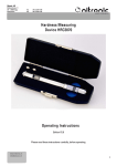
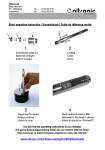
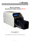
Nitronic AG
Mattenstrasse 11
CH – 2555 Brügg
Switzerland
Tel.
Fax
+41 32 373 70 70
+41 32 373 70 75
MiniStrip Precision Stripping Tool
Operating Instructions
Edition V2/10
Please read through these Operating Instructions carefully before starting work.
Nitronic AG
Mattenstrasse 11
CH – 2555 Brügg
Switzerland
Tel.
Fax
+41 32 373 70 70
+41 32 373 70 75
General
Thank you for your custom and for choosing to purchase this tool from us.
Please read this operating instructions thoroughly in order to ensure the best possible performance from
the tool. The warranty does not extend to damage caused by non-observance of the instructions. We are
not liable for any consequential loss.
Symbols
The following symbols draw your attention to the various danger warning levels indicated in each chapter:
Please adhere strictly to the work practices and procedures indicated in this pictogram. Non-adherence
could cause damage to the tool or the cable.
This pictogram serves to illustrate work and operating procedures which must be adhered to, as well as
to give important information about how the tool works.
Table of Contents
General ........................................................................................................................................ 2
Symbols ....................................................................................................................................... 2
Table of Contents....................................................................................................................... 2
Product description................................................................................................................... 3
Controls ....................................................................................................................................... 3
Operation..................................................................................................................................... 4
Adjusting the centering diameter ............................................................... 4
Adjusting the stripping diameter................................................................. 4
Adjusting the stripping length ..................................................................... 5
Stripping operation ..................................................................................... 5
Adjusting the stripping length with a cable ................................................ 6
Maintenance .............................................................................................................................. 7
Lubrication .................................................................................................. 7
Cleaning ...................................................................................................... 7
Changing the stripping blades (without centering unit) .............................. 7
Changing the stripping blades (with centering unit) ................................... 9
Calibrating the centering device ............................................................... 12
Fault causes.............................................................................................................................. 13
Cable faults ............................................................................................... 13
Operational faults ..................................................................................... 13
Tool faults ................................................................................................. 13
Technical Data ......................................................................................................................... 14
Basic equipment ...................................................................................................................... 14
Standard MiniStrip with HSS blades ........................................................ 14
MiniStrip with Titanium coated carbide blades and centering unit .......... 15
Replacement parts .................................................................................................................. 15
Optional parts ........................................................................................................................... 15
Nitronic AG
Mattenstrasse 11
CH – 2555 Brügg
Switzerland
Tel.
Fax
+41 32 373 70 70
+41 32 373 70 75
Product description
The all new cable stripping tool Nitronic MiniStrip was specially developed for thin cables. It features a
patented four-blade system, which provides accurate and exactly repeated stripping of cables.
The coating is removed by cutting with rotating blades and strip-off in one single step. This simple procedure
allows processing fiberoptic cables as well as coax and Teflon coated cables. The high precision avoids
damage to wires or fibers.
Precision blade diameter control with a micrometer scale, allows a quick set-up of diameter. The locking
screw of the diameter adjusting system makes the tool available even for military applications (mil-spec). The
high quality of the product guaranties a precise repetitiveness.
Brief overview:
•
•
•
•
•
Rotating cut
Stripping head with 4 blades on one plane
Blades replaceable by user without tools
Fast and easy change of length and diameter
mobile, no need for power supply
The Nitronic MiniStrip is exclusively designed to strip copper conductors. Please keep all metal objects
(e.g. screwdriver, tweezers) away from the blades otherwise these will be damaged.
Controls
1. Grip
2. Length setting ring
3. Stopper
4. Diameter setting
5. Stripping head
16. Locking screw (white)
17. Centering scale
5
1
4
16
2
3
17
Nitronic AG
Mattenstrasse 11
CH – 2555 Brügg
Switzerland
Tel.
Fax
+41 32 373 70 70
+41 32 373 70 75
Operation
Adjusting the centering diameter
•
First measure the outer diameter of the cable with the slide gauge.
•
Then set a somewhat larger value on the centering scale (17
17)
17 (approx. + 0.05
0.05 mm).
mm) The divisions of the
centering scale are 0.2
0.2 mm.
mm
The centering diameter should be set as accurately as possible. The stripping result would otherwise be
unsatisfactory.
Blocking of the centering device with the blocking screw (16
16)
white)
16 (white
white is not absolutely necessary.
diameterr
Adjusting the stripping diamete
•
First measure the diameter of the cable with the slide gauge.
•
Then adjust the diameter setting (4) to a slightly larger diameter (approx. + 0.1 mm).
mm) The diameter setting
increments are 0.01
0.01 mm.
mm (Fig. 2)
The stripping diameter should be adjusted as accurately as
possible. Otherwise the stripping result will be insufficient or
the blades will be damaged.
Fig 2 Diameter Setting
Nitronic AG
Mattenstrasse 11
CH – 2555 Brügg
Switzerland
Tel.
Fax
+41 32 373 70 70
+41 32 373 70 75
Adjusting the stripping length
•
Release the length setting ring gauge (2) by twisting it in the direction of the arrow. (Fig. 3)
•
Move the length setting ring gauge (2) and adjust the stopper (3) to the desired length using the setting.
The setting increments are 1 mm per bar.
(Fig. 3)
•
Fix the length setting ring gauge (2) in position by twisting it in the opposite direction. (Fig. 3)
In case of diameters (<0.5 mm) which are to be stripped very
short (3 mm),
mm) the length setting ring gauge (2) should not be fixed
in place, so that when the stripping head (5) is pulled back, the
stripping blades can be opened fully (cleaning effect) (Fig. 4)
2
3
Fig. 3 Lengh setting
Stripping operation
•
•
Pull the stripping head (5) backwards up to the stopper.
The four stripping blades are now fully open. (Fig. 4)
5
Insert the cable horizontally through the head opening, until the
end of the cable is touching the stopper (3).
(3) (Fig. 5)
Fig. 4 Opening the blades
In order to ensure that the stripping lengths are as accurate as
possible, the cable must not be put under too much tension.
3
Fig 5.Insert the cable
Nitronic AG
Mattenstrasse 11
CH – 2555 Brügg
Switzerland
Tel.
Fax
+41 32 373 70 70
+41 32 373 70 75
•
Slowly release the stripping head (5).
(5) The blades will close up to the outer diameter of the cable. (Fig. 6)
•
Start the stripping action by pulling the grip and the cable,
applying a consistent and constant pull. (Fig. 7)
This action will cause the stripping head to start turning and the
blades will cut through the insulation until they reach the
diameter which has been set. The constant pull between the
grip and the cable then causes the insulation to be stripped from
the wire. (Fig. 7)
5
Fig. 6 Close the blades
If the stripping diameter is set too small, the blades will cut into
the conductor and the insulation can then only be stripped off
by pulling harder. This can damage the blades
Fig. 7 Stripping
•
Check that the wire has been stripped with a clean cut and at the correct length. Check and adjust the
stripping diameter and stripping length as necessary.
Adjusting the stripping length with a cable
This procedure is only necessary in cases where the accuracy of
the stripping length is particularly important.
•
•
•
Adjust the diameter.
Release the length setting ring gauge (2) by twisting it in the
direction of the arrow, pull it as far back as it will go and fix into
5
position. (Fig. 9)
9)
Pull the stripping head (5) backwards and insert the cable up to
the desired length using the scale. Holding this position, slowly
Fig. 8 Insert wire to desired length
release the stripping head (5).
(5) (Fig. 8).
8)
Nitronic AG
Mattenstrasse 11
CH – 2555 Brügg
Switzerland
Tel.
Fax
+41 32 373 70 70
+41 32 373 70 75
•
Release the length setting ring gauge again (2) by twisting it in the direction of the arrow, and push
forwards until the stopper (3) is touching the cable. Then fix the length setting ring gauge (2) into position
by twisting it in the opposite direction (Fig. 9).
9) .
•
Strip the cable and check the stripping length. Repeat the
process if necessary.
2
The stripping length is now set and the Nitronic MiniStrip is ready
for further stripping at the same stripping length.
Maintenance
3
Fig. 9 Stopper setting
The only maintenance required is cleaning of the stripping head.
Lubrication
The Nitronic MiniStrip is designed in such a way that it does not require the application of grease or oil.
In order to ensure correct function and long service life, avoid contaminating the tool with greasy or oily
substances.
Cleaning
The waste created by the stripping should be removed after each stripping to avoid placing any unnecessary
stress on the stripping blades.
•
•
•
After stripping, briefly pull the stripping head backwards; this causes the stripping blade to effectively
clean away the waste.
Clean the surface of the stripping head using a dry, clean brush only.
Dirt on the grip, the spindle or the stripping head can be removed using a cloth dampened with kerosene.
unit))
Changing the stripping blades (without centering unit
The stripping blades must only be inspected and replaced by a
suitably trained person.
•
Set the diameter setting (4) to 1 mm.
Fig. 10)
mm (Fig.
10
Fig. 10 Diameter setting
Nitronic AG
Mattenstrasse 11
CH – 2555 Brügg
Switzerland
•
Tel.
Fax
+41 32 373 70 70
+41 32 373 70 75
Unscrew the end cap (6) and carefully pull out the cover plate
(7).
(7) The four stripping blades (8) will now be visible. (Fig. 11)
7
6
8
In order to avoid losing the very small stripping blades, we
recommend that you put down a dark-colored smooth mat and
use a pair of tweezers. All four stripping blades must be changed
at the same time in order to maintain a consistent stripping quality
•
Remove each stripping blade (8) individually from the guide plate
(9).
(9)
•
If necessary, carefully clean the guide plate (9) with a dry brush
•
Insert new stripping blades (8) individually. As far as possible,
align the stripping blades with the track so that the blades do
not subsequently jam. (Fig. 13)
Fig. 11 Removing cap and cover
8
9
10
Fig 13.Insert blades
•
Carefully replace the cover plate (7).
(7) The chamfer (10) must
point towards the outside. (Fig. 14)
7
6
•
Screw the end cap (6) back on again, but do not tighten.
tighten (Fig.
14)
10
Fig. 14 Assemble plate and cover
Nitronic AG
Mattenstrasse 11
CH – 2555 Brügg
Switzerland
Tel.
Fax
+41 32 373 70 70
+41 32 373 70 75
•
Set the diameter setting (4) to a diameter of 0 mm.
mm
•
Slowly push the stripping head (5) back and forth. (Fig. 15)
This will cause the four stripping blades to automatically settle into
the tracks on the guide plate.
6
•
Pull the stripping head (5) backwards as far as it will go and,
holding this position, tighten the end cap (6).
(6)
(Fig. 15)
The Nitronic MiniStrip is now ready for use.
5
Fig. 15 Settle blades
Changing the stripping blades (with centering unit)
The stripping blades must only be inspected and replaced by a suitably trained person.
•
Set the diameter setting (4) to 1.5 mm.
Fig. 10)
mm (Fig.
10
In order to avoid losing the very small stripping blades, we
recommend that you put down a dark-colored smooth mat and
use a pair of tweezers. All four stripping blades must be changed
at the same time in order to maintain a consistent stripping quality
4
Fig. 16. Diameter Setting
Nitronic AG
Mattenstrasse 11
CH – 2555 Brügg
Switzerland
Tel.
Fax
+41 32 373 70 70
+41 32 373 70 75
•
Loosen screw (19) (black),
(black) not the white one (16)!
•
Loosen nut (18)
(18 and centering scale (17) together. ( Fig. 17)
17)
18
17
16
19
Fig. 17 Loosen centering unit
•
The centering device can now be removed as a complete module.
( Fig. 18)
18)
Fig.18 Remove centering device
•
Remove each stripping blade (8) individually from the guide plate
(9).
(9)
•
If necessary, carefully clean the guide plate (9) with a dry brush
•
Insert new stripping blades (8) individually. As far as possible,
align the stripping blades with the track so that the blades do not
subsequently jam.
8
9
Nitronic AG
Mattenstrasse 11
CH – 2555 Brügg
Switzerland
•
Tel.
Fax
+41 32 373 70 70
+41 32 373 70 75
Position and place down the centering device. ( Fig. 20)
Fig. 20 Position centering device
17
•
Screw in centering scale (17) together with the nut (18) as far as
the stop, but do not yet tighten it. (Fig. 21)
•
Set diameter scale (4) to a diameter of 0 mm .
18
Fig. 2 Screw in nut and centering scale
•
Slowly push the stripping head (5) back and forth. (Fig. 22)
22)
5
This will cause the four stripping blades to automatically fit into
the tracks on the guide plate
Fig. 22 Aligning the blades
•
Pull the stripping head (5) backwards as far as will go and, holding this position, tighten the nut (18).
(Fig. 22)
22)
The centering device must now be calibrated in the next operating step.
Nitronic AG
Mattenstrasse 11
CH – 2555 Brügg
Switzerland
Tel.
Fax
+41 32 373 70 70
+41 32 373 70 75
Calibrating the centering device
• Set diameter scale (4) to a diameter of 0 mm . (Fig. 23)
23)
4
Fig. 23 Set diameter
•
By rotating the centering scale (17), fully open the centering jaws (25) and insert calibrating pin (30).
(30)
Then by rotating the centering scale (17) close the centering jaws as far as the calibrating pin (30).
(30) .
(Fig. 24)
24)
17
•
Loosen screw (19) (black) and set centering scale (17) to
diameter 2 mm.
mm Retighten screw (19) (black) and remove
calibrating pin (30).
(30) (Fig. 24)
24)
30
19
Fig. 24 Insert calibrating mandrel
The Nitronic MiniStrip is now ready for use.
Nitronic AG
Mattenstrasse 11
CH – 2555 Brügg
Switzerland
Tel.
Fax
+41 32 373 70 70
+41 32 373 70 75
Fault causes
Cable faults
Fault
Diagnosis
Diagnosis
Remedy
Conductor, shielding or dielectric
is cut
Cable highly eccentric
Incrementally increase the
stripping
diameter
Isolation does not strip off
Diameter differential between
isolation and wire is very small.
Gradually reduce the stripping
diameter.
Fault
Isolation is not stripped off
Diagnosis
Diagnosis
Pull between grip and cable is too
strong or too weak.
Remedy
Apply consistent and constant pull
during stripping.
Isolation does not strip off
Diameter differential between
isolation and wire is very small.
Optimize the stripping diameter.
Diagnosis
Diagnosis
Stripping waste in the stripping
head.
Remedy
Clean by pulling back and releasing
the stripping head several times.
Stripping blades broken or worn.
Change the stripping blades
Operational faults
Tool faults
Fault
Cable will not feed in.
Wire has been cut into.
Poor stripping quality
Stripping head will not go back into Spindle is dirty
the starting position.
Stripping head can no longer be
Guide plate is dirty.
pulled backwards.
Clean the spindle
Remove stripping waste with
brush.
Nitronic AG
Mattenstrasse 11
CH – 2555 Brügg
Switzerland
Tel.
Fax
+41 32 373 70 70
+41 32 373 70 75
Technical
Tech nical Data
Processable wire diameter
Depending on type of insulation possible
Outer cable diameter
Stripping length
Diameter setting
Stripping length setting
Stripping system
Dimensions
Weight
Construction
Stripping blades
Processable insulation materials
Blade change
0.25-1.5mm (AWG 30-15)
up to 0.16mm (AWG 34)
up to 2.5mm
up to 15mm
Increments 0.01mm
Increments 1mm
Rotational cutting action with four blades set at the same
level.
Diameter 18mm Length 165mm
90g
entirely metal construction
HSS, (Titanium coated carbide optional)
PVC, Teflon, Kapton, Tefcel, Kynar etc.
no tools needed
Subject to technical modification without prior notice.
no tice.
Basic equipment
Standard MiniStrip with HSS blades
Quantity Description
Article Number
1
1
1
1
1
1
010065
EN-7210
EN-7110
MiniStrip
Protective cover
Operating instructions
Or short instructions and CD-ROM
Headless blocking screw
Allen Key
Nitronic AG
Mattenstrasse 11
CH – 2555 Brügg
Switzerland
Tel.
Fax
+41 32 373 70 70
+41 32 373 70 75
Titanium
MiniStrip with Titan
ium coated carbide blades and centering unit
Quantity Description
Article Number
1
1
1
1
1
1
1
1
010070
EN-7210
EN-7110
MiniStrip
Protective cover
Operating instructions
Or short operating instructions and CD-ROM
Headless blocking screw
Allen Key
Allen Key
Calibrating mandrel
Replacement parts
Quantity Description
Article Number
1 Set
1Set
1
1
1
1
1
010075
010079
010215
010216
010201
010225
010200
Stripping blades HSS (4 pcs.)
Stripping blades, Titanium coated carbide (4 pcs.)
O-Ring
Sealing cap
Blade cover plate
Guide plate
End cap
Optional
Optional parts
Quantity Description
Article Number
1
1
1
1
1
010080
010199
010086
010089
010088
Bench clamp
Centering unit
Case for MiniStrip
Anti-roll
Tweezers