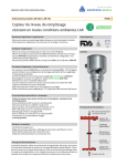
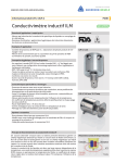
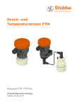
1
S056 INSTALLATION MANUAL
ELECTROMAGNETIC FLOWMETER
Authorization
n. 1178
“FULL BORE” SENSORS MODEL
INDEX
•
•
•
•
•
•
•
•
•
•
INTRODUCTION .................................................................................... 3
START UP AND MAINTENANCE OF THE INSTRUMENTS ........................... 3
SAFETY ................................................................................................. 4
GENERAL INFORMATION ON THE SENSORS INSTALLATION .................... 5
ELECTRICAL CONNECTIONS OF SENSOR TO TRANSMITTER .................... 6
GROUNDING INSTRUCTIONS ................................................................. 6
OVERALL DIMENSIONS .......................................................................... 7
THREADED CONNECTIONS .................................................................... 7
CLAMP CONNECTIONS........................................................................... 8
INSPECTION SCREWS............................................................................ 9
2
S056 FULLBORE installation manual EN.doc
INTRODUCTION
-
-
-
-
-
-
-
This manual is integral part of the product. Read carefully the instructions
contained since it contains important indications for the safety of use and
of maintenance.
The technical information and the relative products of this manual could be
modified without any previous notice.
The flowmeter must be used for the use it has been built for. The improper
use, possible tampering of the instrument or parts of it and substitutions of
any components not original, makes the warranty to decay automatically.
The manufacturer is considered responsible only if the instrument is used in
its original configuration and setting.
The flowmeter makes measures of liquids with conductivity greater than
5µS/cm; it consists of a sensor (described in this manual) and a converter,
for it see the manual provided.
If the sensor is supplied in compact version to the converter, consider the
operating temperatures more restrictive, otherwise refer to the respective
manuals (page 6).
When transporting, unpacking and handling the flowmeter, be careful and
care.
In the case of prolonged storage and of transport, use and store in the
original container in a dry place, do not place more than 3 packs one above
the other. It is possible pallets storage and transport (in case of wooden
crates do not place one above the other).
For the cleaning of the device use only a damp cloth, and for the
maintenance/repairs, contact the customer service.
For the disposal of the device and of the packaging make strict reference to
the regulations.
It is forbidden the reproduction of the present manual and of possible
software supplied with the instrument.
START UP AND MAINTENANCE OF THE INSTRUMENTS
-
Before starting up the instrument, always make a sure connection to
ground as suitable to page 6.
Verify periodically: the cables integrity, the tightening of the sealing
elements (cable glands, covers, etc.), the mechanical fixing of the
instrument on the pipe or on the wall stand.
3
S056 FULLBORE installation manual EN.doc
SAFETY
Before using the instrument, always make a sure connection
to the ground
Avoid any attempt to repair the instrument. If the instrument
is not functioning properly, please call the nearest assistance
service
Pay maximum attention during the operations
ATTENTION !!!
DANGER !!!
4
S056 FULLBORE installation manual EN.doc
GENERAL INFORMATION ON THE SENSORS INSTALLATION
The manufacturer recommends cleaning the instruments before use.
Flow direction
Before install the sensor locate the direction of the liquid in the piping
The sign of the flow rate is positive, when the flow direction is from – to + as
printed on the tag plate.
If after the installation, for plant request becomes necessary reverse the sign of the
flow, it is enough reverse the sign of the coefficient KA
In vertical installations an ascending flow is preferable. For vertical installations with descending flow direction contact the
manufacturer.
For installation in long pipe lines, please use anti vibration joints
LONG PIPE
ANTIVIBRATION
Avoid a partially empty pipe. During operation he pipe must be either completely full of liquid or completely empty.
Install the sensor away from bends and hydraulic accessories.
3 X DN
2 X DN
Avoid positioning fittings by tightening the clamp.
Pipe fitting
Nut
Nut
Pipe fitting
Sensor fitting
Sensor fitting
5
S056 FULLBORE installation manual EN.doc
ELECTRICAL CONNECTIONS OF SENSOR TO TRANSMITTER
(CONNECTIONS TO CONVERTER: SEE PROPER MANUAL)
GROUNDING INSTRUCTIONS
For correct operation of the meter it is NECESSARY that the sensor and the
liquid are equipotential, so ALWAYS connect the sensor and converter to
ground:
6
S056 FULLBORE installation manual EN.doc
OVERALL DIMENSIONS
100
THREADED CONNECTIONS
D
DN
A
L
FITTINGS
FITTINGS
33
100
DIN 11851
DIMENSIONS
mm (inches)
DN
3
(1/8")
6
(1/4)
10
(3/8)
15
(1/2")
20
(3/4")
25
(1")
32
(1"1/4)
40
(1"1/2)
50
(2")
65
(2"1/2)
80
(3")
100
(4”)
A
77
(3.03)
77
(3.03)
77
(3.03)
77
(3.03)
77
(3.03)
100
(3.94)
100
(3.94)
100
(3.94)
100
(3.94)
100
(3.94)
100
(3.94)
100
(3.94)
L
128
(5.04)
128
(5.04)
128
(5.04)
128
(5.04)
128
(5.04)
180
(7.09)
180
(7.09)
180
(7.09)
180
(7.09)
180
(7.09)
200
(7.87)
200
(7.87)
D
76
(3)
76
(3)
76
(3)
76
(3)
76
(3)
76
(3)
89
(3.50)
89
(3.50)
114
(4.49)
140
(5.51)
140
(5.51)
168
(6.61)
CONNECTIONS
DN 10
DN 10
DN 10
DN 15
DN 20
DN25
DN 32
DN 40
DN 50
DN 65
DN 80
DN 100
SMS-1146
DIMENSIONS mm
(inches)
10
(3/8)
15
(1/2")
20
(3/4")
25
(1")
40
(1"1/2)
50
(2")
65
(2"1/2)
80
(3")
100
(4")
A
77
(3.03)
77
(3.03)
77
(3.03)
100
(3.94)
100
(3.94)
100
(3.94)
100
(3.94)
100
(3.94)
100
(3.94)
L
128
(5.04)
128
(5.04)
128
(5.04)
180
(7.09)
180
(7.09)
180
(7.09)
180
(7.09)
200
(7.87)
200
(7.87)
D
76
(3)
76
(3)
76
(3)
76
(3)
89
(3.50)
114
(4.49)
140
(5.51)
140
(5.51)
168
(6.61)
CONNECTIONS
DN 25
DN 25
DN 25
DN25
DN 38
DN 51
DN 63
DN 76
DN 104
NB : With DIN connection use suitable gasket for cleaning in place (CIP) applications
SMS 1146 connection is only suitable for cleaning out of place (COP)
7
S056 FULLBORE installation manual EN.doc
100
CLAMP CONNECTIONS
F
D
I ( Ø INTERNAL FITTING )
A
L
100
FITTINGS
33
FITTINGS
CLAMP ISO 2852
DN
DIMENSIONS mm
(inches)
3
(1/8")
6
(1/4)
10
(3/8)
15
(1/2")
20
(3/4")
25
(1")
40
(1"1/2)
50
(2")
65
(2"1/2)
80
(3")
100
(4")
A
77
(3.03)
77
(3.03)
77
(3.03)
77
(3.03)
77
(3.03)
100
(3.94)
100
(3.94)
100
(3.94)
100
(3.94)
100
(3.94)
100
(3.94)
L
128
(5.04)
128
(5.04)
128
(5.04)
128
(5.04)
128
(5.04)
180
(7.09)
180
(7.09)
180
(7.09)
180
(7.09)
200
(7.87)
200
(7.87)
D
76
(3)
76
(3)
76
(3)
76
(3)
76
(3)
76
(3)
89
(3.50)
114
(4.49)
140
(5.51)
140
(5.51)
168
(6.61)
I
12.7
(0.5)
12.7
(0.5)
12.7
(0.5)
17.2
(0.68)
21.3
(0.84)
22.6
(0.89)
35.6
(1.40)
48.6
(1.91)
60.3
(2.37)
72.9
(2.87)
97.6
(3.84)
F
34
(1.34)
34
(1.34)
34
(1.34)
34
(1.34)
34
(1.34)
50.5
(1.99)
50.5
(1.99)
64
(2.52)
77.5
(3.05)
91
(3.58)
119
(4.69)
CLAMP BS 4825 Part3
DN
DIMENSIONS mm
(inches)
3
(1/8")
6
(1/4)
10
(3/8)
15
(1/2")
20
(3/4")
25
(1")
40
(1"1/2)
50
(2")
65
(2"1/2)
80
(3")
100
(4")
A
77
(3.03)
77
(3.03)
77
(3.03)
77
(3.03)
77
(3.03)
100
(3.94)
100
(3.94)
100
(3.94)
100
(3.94)
100
(3.94)
100
(3.94)
L
128
(5.04)
128
(5.04)
128
(5.04)
128
(5.04)
128
(5.04)
180
(7.09)
180
(7.09)
180
(7.09)
180
(7.09)
200
(7.87)
200
(7.87)
D
76
(3)
76
(3)
76
(3)
76
(3)
76
(3)
76
(3)
89
(3.50)
114
(4.49)
140
(5.51)
140
(5.51)
168
(6.61)
I
9.5
(0.37)
9.5
(0.37)
9.5
(0.37)
15.85
(0.62)
22.2
(0.87)
22.2
(0.87)
34.9
(1.37)
47.6
(1.87)
60.3
(2.37)
73
(2.87)
97.6
(3.84)
F
25.4
(1)
25.4
(1)
25.4
(1)
25.4
(1)
50.5
(1.99)
50.5
(1.99)
50.5
(1.99)
64
(2.52)
77.5
(3.05)
91
(3.58)
119
(4.69)
8
S056 FULLBORE installation manual EN.doc
INSPECTION SCREWS
Verify periodically the sensor’s seals integrity: with
piping full of liquid, unscrew the Inspection
screws (see drawing aside) and verify the total
absence of liquid from inspection hole!
After the above operation, REMEMBER to close
again the holes.
In case of leakage contact immediately our
Customer Service.
Inspection
screw
3°
When flowmeter is installed horizontally, ensure minimum angle of 3° for self-draining purposes
9
S056 FULLBORE installation manual EN.doc
10
S056 FULLBORE installation manual EN.doc
S056
INSTALLATIONSANLEITUNG
ELEKTROMAGNETISCHES DURCHFLUSSMESSGERÄT
Berechtigung
n. 1178
“FULL BORE” SENSORS
INHALTSVERZEICHNIS
•
•
•
•
•
•
•
•
•
•
EINLEITUNG ......................................................................................... 3
INBETRIEBNAHME UND WARTUNG DER GERÄTE .................................... 3
SICHERHEIT ......................................................................................... 4
ALLGEMEINE INFORMATIONEN ZUR INSTALLATION DER SENSOREN....... 5
ELEKTRISCHE VERBINDUNGEN ZWISCHEN SENSOR UND TRANSMITTER . 6
ERDUNGSANWEISUNGEN ...................................................................... 6
ABMESSUNGEN ..................................................................................... 7
GEWINDE ANSCHLUSS .......................................................................... 7
CLAMP ANSCHLUSS ............................................................................... 8
INSPEKTIONSSCHRAUBE ....................................................................... 9
2
S056 FULLBORE installation manual DE.doc
EINLEITUNG
-
-
-
-
-
-
-
Dieses Handbuch ist integraler Bestandteil des Gerätes. Lesen Sie die hierin
enthaltenen Anweisungen sorgfältig durch, da sie wichtige Hinweise zur
sicheren Verwendung und zur Wartung enthalten.
Änderungen der technischen Daten der in diesem Handbuch genannten
Produkte sind ohne Vorankündigung vorbehalten.
Das Durchflussmessgerät muss für den Zweck verwendet werden, für den
es entwickelt wurde. Bei unsachgemäßer Verwendung, Manipulationen des
Gerätes oder seiner Komponenten oder Einsatz von Ersatzteilen anderer
Hersteller verfällt sofort jeglicher Garantieanspruch.
Der Hersteller ist nur haftbar, wenn das Gerät in seiner
Originalkonfiguration und -einstellung verwendet wird.
Das Durchflussmessgerät nimmt Messungen an Flüssigkeiten mit einer
Leitfähigkeit von über 5µS/cm vor; es besteht aus einem Sensor (in dieser
Anleitung beschrieben) und einem Transmitter, für letzteren siehe das
entsprechende Handbuch.
Wenn der Sensor in der Kompaktversion mit Transmitter geliefert wird,
bitte beachten, dass die Betriebstemperaturgrenzwerte restriktiver sind.
Für Details siehe die jeweiligen Handbücher (Seite 6).
Bei Transport, Auspacken und Handhabung des Durchflussmessers
vorsichtig und sorgfältig vorgehen.
Bei längerfristiger Lagerung und beim Transport den Originalbehälter an
einem trockenen Ort lagern, dabei nicht mehr als 3 Packungen
übereinander stapeln. Für Lagerung und Transport können Paletten
verwendet werden (im Fall von Holzkisten: nicht stapeln).
Zur Reinigung des Gerätes nur ein feuchtes Tuch verwenden, und für die
Wartung/Reparaturen den Kundendienst kontaktieren.
Bei der Entsorgung des Gerätes und der Verpackung die gesetzlichen
Bestimmungen strikt einhalten.
Die Vervielfältigung dieses Handbuchs und jeglicher mit diesem Gerät
gelieferten Software ist verboten.
INBETRIEBNAHME UND WARTUNG DER GERÄTE
-
Vor Inbetriebnahme des Gerätes immer eine geeignete sichere
Erdungsverbindung sicherstellen, wie auf Seite 6 angegeben.
Überprüfen Sie in regelmäßigen Abständen: die Unversehrtheit der Kabel,
den festen Sitz der Dichtelemente (Kabelmuffen, Abdeckungen usw.), die
mechanische Befestigung des Gerätes an der Rohrleitung oder der
Wandhalterung.
3
S056 FULLBORE installation manual DE.doc
SICHERHEIT
Vor Einsatz des Gerätes immer eine sichere
Erdungsverbindung herstellen
Nicht versuchen, das Gerät zu reparieren. Wenn das Gerät
nicht korrekt arbeitet, wenden Sie sich bitte an den
nächstgelegenen Kundendienst
Während des Betriebs maximale Aufmerksamkeit aufwenden
ACHTUNG!!!
GEFAHR!!!
4
S056 FULLBORE installation manual DE.doc
ALLGEMEINE INFORMATIONEN ZUR INSTALLATION DER SENSOREN
Der Hersteller empfehlt die Geräte vor der Verwendung zu reinigen.
Strömungsrichtung
Vor Installation des Sensors die Strömungsrichtung in der Rohrleitung beachten.
Das Vorzeichen des Durchflusses ist positiv, wenn die Strömungsrichtung von –
nach + verläuft, wie auf dem Typenschild angegeben.
Wenn das Vorzeichen des Durchflusses nach der Installation gewechselt werden
muss, reicht es, das Vorzeichen des Koeffizienten KA zu wechseln.
Bei senkrechten Installationen ist eine Strömungsrichtung nach oben zu bevorzugen. Für senkrechte Installationen mit
Strömungsrichtung nach unten wenden Sie sich bitte an den Hersteller.
Für Installationen an langen Rohrleitungen bitte schwingungsdämpfende Dichtungen verwenden.
SCHWINGUNGSDÄMPFENDE
VORRICHTUNG
LANGE ROHRLEITUNGEN
Teilweise leere Rohrleitungen vermeiden. Im Betrieb muss die Rohrleitung ganz mit Flüssigkeit gefüllt oder völlig leer sein.
Installieren Sie den Sensor von Krümmungen und Hydraulikzubehör weg.
3 X DN
2 X DN
Positionierung der Fittings durch Anziehung der Klemme vermeiden
Rohrleitungsanschluss
Mutter
Mutter
Rohrleitungsanschluss
Sensoranschluss
Sensoranschluss
5
S056 FULLBORE installation manual DE.doc
ELEKTRISCHE VERBINDUNGEN ZWISCHEN SENSOR UND TRANSMITTER
(ANSCHLUSS DES TRANSMITTERS: SIEHE EIGENES HANDBUCH)
ERDUNGSANWEISUNGEN
Für den korrekten Betrieb des Durchflussmessgerätes ist es NOTWENDIG, dass
der Sensor und die Flüssigkeit dasselbe Potential haben. Schließen Sie daher
IMMER den Sensor und den Transmitter an Erdpotential an:
6
S056 FULLBORE installation manual DE.doc
ABMESSUNGEN
GEWINDE ANSCHLUSS
10
DN
D
A
L
ANSCHLUSS
ANSCHLUSS
100
33
DIN 11851
Abmessungen
mm (Zoll)
DN
3
(1/8")
6
(1/4)
10
(3/8)
15
(1/2")
20
(3/4")
25
(1")
32
(1"1/4)
40
(1"1/2)
50
(2")
65
(2"1/2)
80
(3")
100
(4”)
A
77
(3,03)
77
(3,03)
77
(3,03)
77
(3,03)
77
(3,03)
100
(3,94)
100
(3,94)
100
(3,94)
100
(3,94)
100
(3,94)
100
(3,94)
100
(3,94)
L
128
(5,04)
128
(5,04)
128
(5,04)
128
(5,04)
128
(5,04)
180
(7,09)
180
(7,09)
180
(7,09)
180
(7,09)
180
(7,09)
200
(7,87)
200
(7,87)
D
76
(3)
76
(3)
76
(3)
76
(3)
76
(3)
76
(3)
89
(3,50)
89
(3,50)
114
(4,49)
140
(5,51)
140
(5,51)
168
(6,61)
Anschluss
DN 10
DN 10
DN 10
DN 15
DN 20
DN25
DN 32
DN 40
DN 50
DN 65
DN 80
DN 100
SMS-1146
Abmessungen mm
(Zoll)
10
(3/8)
15
(1/2")
20
(3/4")
25
(1")
40
(1"1/2)
50
(2")
65
(2"1/2)
80
(3")
100
(4")
A
77
(3,03)
77
(3,03)
77
(3,03)
100
(3,94)
100
(3,94)
100
(3,94)
100
(3,94)
100
(3,94)
100
(3,94)
L
128
(5,04)
128
(5,04)
128
(5,04)
180
(7,09)
180
(7,09)
180
(7,09)
180
(7,09)
200
(7,87)
200
(7,87)
D
76
(3)
76
(3)
76
(3)
76
(3)
89
(3,50)
114
(4,49)
140
(5,51)
140
(5,51)
168
(6,61)
Anschluss
DN 25
DN 25
DN 25
DN25
DN 38
DN 51
DN 63
DN 76
DN 104
NB : Bei DIN-Anschluss: geeignete Dichtungen für Reinigung an Ort (CIP-Anwendungen)
verwenden.
SMS 1146-Anschluss ist nur geeignet für Reinigungen von Ort (COP)
7
S056 FULLBORE installation manual DE.doc
CLAMP ANSCHLUSS
10
I (FITTING
INNENDURCHMESSER)
F
D
A
L
100
ANSCHLUSS
ANSCHLUSS
33
CLAMP ISO 2852
DN
Abmessungen mm
(Zoll)
3
(1/8")
6
(1/4)
10
(3/8)
15
(1/2")
20
(3/4")
25
(1")
40
(1"1/2)
50
(2")
65
(2"1/2)
80
(3")
100
(4")
A
77
(3,03)
77
(3,03)
77
(3,03)
77
(3,03)
77
(3,03)
100
(3,94)
100
(3,94)
100
(3,94)
100
(3,94)
100
(3,94)
100
(3,94)
L
128
(5,04)
128
(5,04)
128
(5,04)
128
(5,04)
128
(5,04)
180
(7,09)
180
(7,09)
180
(7,09)
180
(7,09)
200
(7,87)
200
(7,87)
D
76
(3)
76
(3)
76
(3)
76
(3)
76
(3)
76
(3)
89
(3,50)
114
(4,49)
140
(5,51)
140
(5,51)
168
(6,61)
I
12,7
(0,5)
12,7
(0,5)
12,7
(0,5)
17,2
(0,68)
21,3
(0,84)
22,6
(0,89)
35,6
(1,40)
48,6
(1,91)
60,3
(2,37)
72,9
(2,87)
97,6
(3,84)
F
34
(1,34)
34
(1,34)
34
(1,34)
34
(1,34)
34
(1,34)
50,5
(1,99)
50,5
(1,99)
64
(2,52)
77,5
(3,05)
91
(3,58)
119
(4,69)
CLAMP BS 4825 Teil3
DN
Abmessungen mm
(Zoll)
3
(1/8")
6
(1/4)
10
(3/8)
15
(1/2")
20
(3/4")
25
(1")
40
(1"1/2)
50
(2")
65
(2"1/2)
80
(3")
100
(4")
A
77
(3,03)
77
(3,03)
77
(3,03)
77
(3,03)
77
(3,03)
100
(3,94)
100
(3,94)
100
(3,94)
100
(3,94)
100
(3,94)
100
(3,94)
L
128
(5,04)
128
(5,04)
128
(5,04)
128
(5,04)
128
(5,04)
180
(7,09)
180
(7,09)
180
(7,09)
180
(7,09)
200
(7,87)
200
(7,87)
D
76
(3)
76
(3)
76
(3)
76
(3)
76
(3)
76
(3)
89
(3,50)
114
(4,49)
140
(5,51)
140
(5,51)
168
(6,61)
I
9,5
(0,37)
9,5
(0,37)
9,5
(0,37)
15,85
(0,62)
22,2
(0,87)
22,2
(0,87)
34,9
(1,37)
47,6
(1,87)
60,3
(2,37)
73
(2,87)
97,6
(3,84)
F
25,4
(1)
25,4
(1)
25,4
(1)
25,4
(1)
50,5
(1,99)
50,5
(1,99)
50,5
(1,99)
64
(2,52)
77,5
(3,05)
91
(3,58)
119
(4,69)
8
S056 FULLBORE installation manual DE.doc
INSPEKTIONSSCHRAUBE
Regelmäßig
die
Unversehrtheit
der
Sensordichtungen überprüfen: Bei ganz mit
Flüssigkeit
gefüllter
Rohrleitung
die
Inspektionsschrauben (siehe nebenstehende
Zeichnung) lösen, dabei muss die Kontrolle
ergeben, dass keinerlei Flüssigkeit aus dem
Inspektionsloch austritt!
Nach dem o.g. Vorgang DARAN DENKEN, die
Löcher wieder zu verschließen.
Im Fall von Flüssigkeitsaustritt wenden Sie sich
sofort an unseren Kundendienst.
Inspektionsschraube
3°
Bei horizontaler Installation des Durchflussmessgerätes einen Neigungswinkel von mindestens 3°,
um eine Selbstentleerung zu ermöglichen.
9
S056 FULLBORE installation manual DE.doc
10
S056 FULLBORE installation manual DE.doc
S056 MANUEL D’INSTALLATION
DÉBITMÈTRE ÉLECTROMAGNÉTIQUE
Autorisation
n. 1178
CAPTEURS À PASSAGE
INTÉGRAL
TABLE DES MATIÈRES
•
•
•
•
•
•
•
•
•
•
INTRODUCTION .................................................................................... 3
DÉMARRAGE ET ENTRETIEN DES INSTRUMENTS .................................... 3
SÉCURITÉ ............................................................................................. 4
INFORMATIONS GÉNÉRALES SUR L'INSTALLATION DU CAPTEUR ............ 5
BRANCHEMENTS ÉLECTRIQUES ENTRE LE CAPTEUR
ET LE TRANSMETTEUR .......................................................................... 6
INSTRUCTIONS DE MISE À LA TERRE..................................................... 6
DIMENSIONS ........................................................................................ 7
RACCORDEMENTS FILETÉS .................................................................... 7
RACCORDEMENT CLAMP ........................................................................ 8
VIS D’INSPECTION ................................................................................ 9
2
S056 FULLBORE installation manual FR.doc
INTRODUCTION
-
-
-
-
-
-
-
Le présent manuel fait partie intégrante du produit. Lisez attentivement les
instructions qu’il contient car elles donnent des indications importantes
pour une utilisation et un entretien en toute sécurité.
Les informations techniques et produits correspondants du manuel peuvent
être modifiés sans avertissement préalable.
Le débitmètre doit être utilisé dans le but pour lequel il a été conçu. Toute
utilisation inadéquate, modification non autorisée de l’appareil ou de ses
pièces, ainsi que tout remplacement d’un ou plusieurs des composants
d’origine invalident automatiquement la garantie.
La responsabilité du fabricant est engagée uniquement si l’appareil est
utilisé dans sa configuration et avec ses réglages d’origine.
Le débitmètre effectue des mesures de liquides dont la conductivité est
supérieure à 5µS/cm ; il se compose d’un capteur (décrit dans ce manuel)
et d’un transmetteur (pour ce dernier, voir le manuel fourni).
Si le capteur est ajouté au transmetteur en version compacte, il est
recommandé d’envisager une plage de températures d’exploitation plus
restreinte, ou de consulter les manuels correspondants (page 6).
Transportez, déballez et manipulez le débitmètre avec précaution.
En cas de stockage prolongé et lors du transport, placez l’appareil dans son
emballage d’origine, à l’abri de l’humidité, et n’empilez pas plus de 3
paquets les uns au-dessus des autres. Le stockage et le transport sur
palettes est possible (si l’emballage est une caisse en bois, ne pas empiler
les caisses).
L’appareil doit être nettoyé exclusivement avec un linge humide. Pour les
opérations de maintenance et les réparations, contactez le service clientèle.
Pour la mise au rebut de l’appareil et de l’emballage, respectez la
réglementation en vigueur.
La reproduction du présent manuel et de tout logiciel fourni avec
l'instrument est interdite.
DÉMARRAGE ET ENTRETIEN DES INSTRUMENTS
-
-
Avant de démarrer l’instrument, établissez systématiquement une
connexion de mise à la terre sécurisée comme indiqué page 6.
Vérifiez périodiquement : l’intégrité des câbles, le serrage des éléments
d'étanchéité (passe-câbles, couvercles, etc.) et la fixation mécanique de
l’instrument sur la conduite ou le support mural.
3
S056 FULLBORE installation manual FR.doc
SÉCURITÉ
Avant d’utiliser l’instrument, établissez systématiquement une
connexion de mise à la terre sécurisée.
N’essayez jamais de réparer vous-même l’instrument. Si
l’instrument ne fonctionne pas correctement, contactez le
service d’assistance le plus proche.
Soyez extrêmement attentifs durant les opérations.
ATTENTION !!!
DANGER !!!
4
S056 FULLBORE installation manual FR.doc
INFORMATIONS GÉNÉRALES SUR L'INSTALLATION DU CAPTEUR
Le fabricant recommande de nettoyer l'appareil avant de l'utiliser.
Sens du débit
Avant d’installer le capteur, déterminez le sens d’écoulement du liquide dans la
conduite. Le signe du débit est positif lorsque le sens du débit va de – vers +,
comme indiqué sur la plaque signalétique.
Si l’appareil est monté à l’envers, le signe du débit peut être corrigé en modifiant le
signe du coefficient KA.
Sur une installation verticale, il est préférable d’avoir un débit ascendant. Pour des installations verticales avec sens du débit
descendant, contactez le fabricant.
Pour des installations sur une longue conduite, utilisez des joints anti-vibrations.
ANTI-VIBRATIONS
CONDUITE LONGUE
Évitez une conduite en partie vide. Durant le fonctionnement, la conduite doit être entièrement remplie de liquide ou
complètement vide.
Installez le capteur à l’écart des coudes et des composants hydrauliques.
3 X DN
2 X DN
Évitez la mise en place des raccords par serrage de l’écrou.
Raccord conduite
Fitting
Écrou
Écrou
Raccord conduite
Fitting
Raccord capteur
Raccord capteur
5
S056 FULLBORE installation manual FR.doc
BRANCHEMENTS ÉLECTRIQUES ENTRE LE CAPTEUR ET LE TRANSMETTEUR
(BRANCHEMENTS VERS LE TRANSMETTEUR : VOIR LE MANUEL CORRESPONDANT)
INSTRUCTIONS DE MISE À LA TERRE
Pour un fonctionnement correct du débitmètre, il est IMPÉRATIF que le capteur
et le liquide aient le même potentiel : par conséquent, vous devez TOUJOURS
mettre à la terre le capteur et le transmetteur.
6
S056 FULLBORE installation manual FR.doc
DIMENSIONS
RACCORDEMENTS FILETÉS
100
DN
D
A
L
RACCORDEMENT
RACCORDEMENT
100
33
DIN 11851
DIMENSIONS
mm (Pouce)
DN
3
(1/8")
6
(1/4)
10
(3/8)
15
(1/2")
20
(3/4")
25
(1")
32
(1"1/4)
40
(1"1/2)
50
(2")
65
(2"1/2)
80
(3")
100
(4”)
A
77
(3,03)
77
(3,03)
77
(3,03)
77
(3,03)
77
(3,03)
100
(3,94)
100
(3,94)
100
(3,94)
100
(3,94)
100
(3,94)
100
(3,94)
100
(3,94)
L
128
(5,04)
128
(5,04)
128
(5,04)
128
(5,04)
128
(5,04)
180
(7,09)
180
(7,09)
180
(7,09)
180
(7,09)
180
(7,09)
200
(7,87)
200
(7,87)
D
76
(3)
76
(3)
76
(3)
76
(3)
76
(3)
76
(3)
89
(3,50)
89
(3,50)
114
(4,49)
140
(5,51)
140
(5,51)
168
(6,61)
Raccordement
DN 10
DN 10
DN 10
DN 15
DN 20
DN25
DN 32
DN 40
DN 50
DN 65
DN 80
DN 100
SMS-1146
DIMENSIONS mm
(Pouce)
10
(3/8)
15
(1/2")
20
(3/4")
25
(1")
40
(1"1/2)
50
(2")
65
(2"1/2)
80
(3")
100
(4")
A
77
(3,03)
77
(3,03)
77
(3,03)
100
(3,94)
100
(3,94)
100
(3,94)
100
(3,94)
100
(3,94)
100
(3,94)
L
128
(5,04)
128
(5,04)
128
(5,04)
180
(7,09)
180
(7,09)
180
(7,09)
180
(7,09)
200
(7,87)
200
(7,87)
D
76
(3)
76
(3)
76
(3)
76
(3)
89
(3,50)
114
(4,49)
140
(5,51)
140
(5,51)
168
(6,61)
Raccordement
DN 25
DN 25
DN 25
DN25
DN 38
DN 51
DN 63
DN 76
DN 104
NB : Avec un raccordement DIN, utilisez des joints appropriés pour des applications de
nettoyage en place (NEP).
Un raccordement SMS 1146 est uniquement approprié pour des applications de
nettoyage « hors place »(COP)
7
S056 FULLBORE installation manual FR.doc
RACCORDEMENT CLAMP
10
0
I ( Ø RACCORDEMENT INTERNE )
F
D
A
L
100
RACCORDEMENT
RACCORDEMENT
33
CLAMP ISO 2852
DN
DIMENSIONS mm
(Pouce)
3
(1/8")
6
(1/4)
10
(3/8)
15
(1/2")
20
(3/4")
25
(1")
40
(1"1/2)
50
(2")
65
(2"1/2)
80
(3")
100
(4")
A
77
(3,03)
77
(3,03)
77
(3,03)
77
(3,03)
77
(3,03)
100
(3,94)
100
(3,94)
100
(3,94)
100
(3,94)
100
(3,94)
100
(3,94)
L
128
(5,04)
128
(5,04)
128
(5,04)
128
(5,04)
128
(5,04)
180
(7,09)
180
(7,09)
180
(7,09)
180
(7,09)
200
(7,87)
200
(7,87)
D
76
(3)
76
(3)
76
(3)
76
(3)
76
(3)
76
(3)
89
(3,50)
114
(4,49)
140
(5,51)
140
(5,51)
168
(6,61)
I
12,7
(0,5)
12,7
(0,5)
12,7
(0,5)
17,2
(0,68)
21,3
(0,84)
22,6
(0,89)
35,6
(1,40)
48,6
(1,91)
60,3
(2,37)
72,9
(2,87)
97,6
(3,84)
F
34
(1,34)
34
(1,34)
34
(1,34)
34
(1,34)
34
(1,34)
50,5
(1,99)
50,5
(1,99)
64
(2,52)
77,5
(3,05)
91
(3,58)
119
(4,69)
CLAMP BS 4825 PARTIE3
DN
DIMENSIONS mm
( Pouce )
3
(1/8")
6
(1/4)
10
(3/8)
15
(1/2")
20
(3/4")
25
(1")
40
(1"1/2)
50
(2")
65
(2"1/2)
80
(3")
100
(4")
A
77
(3,03)
77
(3,03)
77
(3,03)
77
(3,03)
77
(3,03)
100
(3,94)
100
(3,94)
100
(3,94)
100
(3,94)
100
(3,94)
100
(3,94)
L
128
(5,04)
128
(5,04)
128
(5,04)
128
(5,04)
128
(5,04)
180
(7,09)
180
(7,09)
180
(7,09)
180
(7,09)
200
(7,87)
200
(7,87)
D
76
(3)
76
(3)
76
(3)
76
(3)
76
(3)
76
(3)
89
(3,50)
114
(4,49)
140
(5,51)
140
(5,51)
168
(6,61)
I
9,5
(0,37)
9,5
(0,37)
9,5
(0,37)
15,85
(0,62)
22,2
(0,87)
22,2
(0,87)
34,9
(1,37)
47,6
(1,87)
60,3
(2,37)
73
(2,87)
97,6
(3,84)
F
25,4
(1)
25,4
(1)
25,4
(1)
25,4
(1)
50,5
(1,99)
50,5
(1,99)
50,5
(1,99)
64
(2,52)
77,5
(3,05)
91
(3,58)
119
(4,69)
8
S056 FULLBORE installation manual FR.doc
VIS D’INSPECTION
Vérifiez régulièrement l’intégrité des joints du
capteur : avec une conduite remplie de liquide,
dévissez les vis d’inspection (voir schéma cicontre) et assurez-vous de l’absence totale de
liquide dans le trou d’inspection.
Une fois cette opération terminée, N’OUBLIEZ PAS
de refermer les trous.
En cas de fuite, contactez immédiatement notre
service clientèle.
Vis
d’inspection
3°
Si le débitmètre est installé à l’horizontale, prévoyez un angle minimum de 3° pour l’autovidange.
9
S056 FULLBORE installation manual FR.doc
10
S056 FULLBORE installation manual FR.doc