1
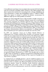
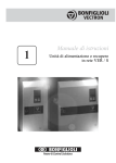
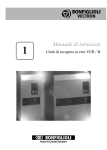
Miniature susceptometer
User Manual
Cevey Laurent
[email protected]
December 24, 2008
Contents
1 Introduction
1.1 Susceptometers . . . . . . . . . . . . . . . . . . . . . . . . . . . . . . . . . .
1.2 Motivations . . . . . . . . . . . . . . . . . . . . . . . . . . . . . . . . . . . .
1
2
2
2 Technical specifications
2.1 Design . . . . . . . . . . . . . . . .
2.2 Geometrical characteristics . . . . .
2.3 Calibration and background signal .
2.4 Field configuration . . . . . . . . .
.
.
.
.
.
.
.
.
.
.
.
.
.
.
.
.
.
.
.
.
.
.
.
.
.
.
.
.
.
.
.
.
.
.
.
.
.
.
.
.
.
.
.
.
.
.
.
.
.
.
.
.
.
.
.
.
.
.
.
.
.
.
.
.
.
.
.
.
.
.
.
.
.
.
.
.
.
.
.
.
2
2
4
4
5
3 User instructions
3.1 Preliminary caution on manipulation . . .
3.2 General Instructions . . . . . . . . . . . .
3.3 Use in SQUID environnement . . . . . . .
3.4 Use in pressure cell . . . . . . . . . . . . .
3.5 Comment on breaking/repairing the MSM
.
.
.
.
.
.
.
.
.
.
.
.
.
.
.
.
.
.
.
.
.
.
.
.
.
.
.
.
.
.
.
.
.
.
.
.
.
.
.
.
.
.
.
.
.
.
.
.
.
.
.
.
.
.
.
.
.
.
.
.
.
.
.
.
.
.
.
.
.
.
.
.
.
.
.
.
.
.
.
.
.
.
.
.
.
.
.
.
.
.
.
.
.
.
.
5
5
5
6
7
8
1
.
.
.
.
.
.
.
.
.
.
.
.
Introduction
This user manual’s purpose is to help the user to get familiar with the miniature susceptometer (MSM) and to allow them to make use of it in the most conscious manner. It also
contains instructions and advice on the last tasks to be done before putting the MSM to real
use. Hopefully this will help and lead to the obtaining of interesting datas and results.
1
1.1
Susceptometers
As their name indicates, The purpose of susceptometers is to measure the magnetic susceptibility χ of materials. AC susceptometers specifically allow a direct measurement of the
actual AC susceptibility ( dM
), whereas other tools (such as SQUID magnetometers) need
dH
computing the gradient of the magnetisation curve M (H). AC susceptometers basically use
3 coils: a primary and a pair of balanced secondaries (the details of the structure and working principle will be given in the design section 2.1).
Susceptometers come in different shapes, designs and sizes, ranging them from versatile to
very specific tools.
1.2
Motivations
The first purpose of constructing a miniature susceptometer is to allow its use in an extreme environnement, namely under very high pressures P ≈ 30kbar. A clamp pressure cell
achieving those conditions has been designed and build at LQM, with an inner diameter of
≈ 5 mm. Other methods consist in having the whole pressure cell with sample inside a large
susceptometer. The advantage of the miniature susceptometer is to fit entirely inside the
P-cell, thus potentially dramatically improving the sensitivity of the measurement.
One of the original goals of the miniature coil is to measure SCBO (SrCu2 (BO3 )2 ) in the
P-cell, and to observe a possible quantum phase transition. At this date, this measurement
hasn’t been achieved yet.
2
Technical specifications
This part contains the full description of the MSM: its design, construction, dimensions and
the characteristics of the magnetic field when plugging the MSM to a voltage source.
2.1
Design
The design was proposed by Ivica Zivkovic and follows those of miniaturized AC susceptometers with a primary coil and a pair of balanced secondaries. The purpose of the miniature
dimensions of the susceptometer is to fit it inside a clamp-type pressure cell.
The general structure of an AC susceptometer is first recalled. Those typically use
insulated copper wire wound up in a certain number of turns and on several layers, forming 3
different coils: a primary coil plugged to an AC voltage source, creating the uniform external
oscillating magnetic field in which bathe a pair of balanced secondaries. Induction in the
secondaries from an applied field of amplitude Hac will lead to an AC tension at the edge
of those. Furthermore, the two secondaries are connected in an ”anti-series” circuit, with
the goal of cancelling most of the background signal (this naturally requires the secondaries
to be as identical as possible). From this basic situation, we can insert a sample in one
of the secondaries, which modifies the magnetic permeability µ of the space filled by the
2
sample. This will result in an unbalance of the 2 secondaries directly linked to the magnetic
permeability of the sample and thus to its magnetic susceptibility through the relation µ =
µ0 (1 + χ). A generic example of such a device is shown on Fig.1.
Figure 1: Scheme of a generic AC susceptometer
The building part was mostly achieved during my internship at LQM this summer (2008).
It was achieved using a home-made set-up, already in use for making coils for other susceptometers. The supporting structure for building the coil – side walls and the inner base
rod – were made out of Teflon. This was the main ”trick” to optimize the compactness
of the susceptometer. Indeed, other susceptometers often include a permanent supporting
structure on which the coils are wound up, but here the idea was to maximize the available
space for the sample, while minimizing the inner diameter of the coils, thus offering a higher
sensitivity. This was achieved by mounting the coils on a 1mm Teflon rod, while ensuring
a firm Stycast base in the first layers, and by removing the supporting rod once the susceptometer finished.
A concentric arrangement of the coils was chosen, the secondaries sandwiching the primary in order to perform calibration on the outer secondary coil. The coils, as well as the
whole device, are made solid by using Stycast Epoxy resin. The advantage of using Stycast
is mostly its excellent strengh and adhesive properties, but also the long time of curation
which allows a working time of over 2h. For the last layers (eventually after calibration, for
the last layer only), GE varnish has been used to fix the coil, leaving possibility for future
modifications on the coil. The design with 3 coils stacked coils naturally gives 6 wires coming
out of the MSM in total, those have been kept pretty long (L ≈ 10 cm) but can be eventually shortened to the minimum sufficient length. The necessary connection: S1in − S2in
or S1out − S2out has until now been made far from the coils, leaving the whole length of the
3
wires available for different future set-up of the MSM.
Technical details on the coils are given in the next section, 2.2.
Figure 2 shows an early image of the MSM at the construction stage.
Figure 2: Picture under microscope of the MSM after finishing the first mounting stage:
winding up the 16 layers of the coils, and before pulling the inner teflon rod out. The layers
are visible on the edge, as well as the 6 outgoing wires.
2.2
Geometrical characteristics
The dimensions and design characteristics of the MSM are now detailed.
Composing elements 50 µm Cu wire, Stycast Epoxy resin, GE varnish.
Layers and turns LS1 = 12 - NS1 ≈ 570, LP = 10 - NP ≈ 470 and LS2 = 4 - NS2 ≈ 160
for the inner secondary, the primary and the outer secondary, respectively (where the
last layer of secondary 2 was only partially filled, see the calibration part).
Dimensions Inner diameter: d = 1 mm, Outer diameter: D = 4 mm, Length: L = 3 mm.
2.3
Calibration and background signal
A critical part of the coil-making is the calibration between the 2 secondaries for minimizing
the background signal. To this end, 2 extra layers (with regard to the original 3 and a halflayers from the design computations) were first wound up on the external secondary. After
2 calibration processes, the final optimized structure of the coil was settled with 3 layers and
14 extra turns on the 4th layer, carefully wound up in the middle part of the layer. The
background signal has been measured in liquid Na (T = 77 K) for a value of:
<(UBG (T = 77K)) = 3.16 µV
4
with applied excitation I = 1 mA, ν = 1 kHz, and where the imaginary part of the signal
was neglectible (the phase is θ = −90 deg with respect to applied excitation, due to the
induction derivative relation UBG ∼ dΦH /dt ∼ dI/dt ).
A later measurement in liquid He (T = 4.2 K) has given a background signal of:
|UBG (T = 4.2K)| = 3.604 µV,
θBG = −79.8
with I = 1 mA, ν = 990 Hz. Here an out-of-phase, dissipative part of the signal exists,
which is a certain deviation from the ideal case.
From the calibration computations, in particular the approximate signal value of ≈ 5.3 µV
per turn, it seems difficult to lower the BG signal more. Naturally, the important factor is
then the sample signal with BG signal ratio.
2.4
Field configuration
A computation with a specific program for modelling susceptometers has given a field value
at the boundaries of the coils of about 853 Oes/A and in the middle of about 1361 Oes/A.
The average over the whole length using a quadratic regression then gives a value of field:
H = 1192 Oes/A.
The main purpose of knowing this value is to try determine the absolute scaling factor giving
the relation: UMSM [V] ∼ χ [SI]. No such relationship could yet be established.
3
3.1
User instructions
Preliminary caution on manipulation
It is necessary to emphasize on the fragility of the device. Naturally, its very small size and
specifically the use of 50 µm Cu wire makes its manipulation most delicate. The most fragile
part is the side of the MSM where the wires stick out of the coils (a connection there has
already broken once, see section 3.5).
As basic care measures, the user should always be patient while manipulating the coil, and
ideally shouldn’t let the coil be hanging by holding the wires and lifting it up! The body
part, held with stycast and GE varnish, can be more safely touched and can be used for
holding the coil with tweezers.
3.2
General Instructions
First, we describe the circuit which is to be set up for measuring with the MSM. This is
mostly shown on Fig.3.
A basic but important remark is now in order. Generally, excitation is supplied by a voltage
source, but what matters in our enquiry is actually a control of the current flowing through
the primary coil. Thus, a conversion has to be made with the problem that a changing resistance requires an adapted voltage for getting the same current. This is most simply done by
5
inserting a 1 Ohm resistance in the primary coil circuit, and setting the excitation voltage
in order to get the desired signal at the 1 Ohm resistance boundaries (typically, chosing a
current I = 1 mA).
Figure 3: Scheme of the general circuit for measurement with the MSM.
As for the samples that can be used in the MSM, most crystals are suitable. A powder
sample has proven to be difficult to prepared for measurement in the MSM, because of the
small dimensions. Naturally, the crystal sample is to be chosen and prepared in order to
fill up the largest space possible inside the MSM. This will give the best sensitivity and will
make it most likely to get a signal from the sample. The ideal sample configuration is thus
a 3 mm long crystal rod with diameter ≈ 0.9 mm. Various methods can be used for cutting
a crystal in the right dimension and shape.
3.3
Use in SQUID environnement
As preliminary, testing measurements, it was proposed to measure temperature dependance
of certain given materials. The SQUID (Superconducting Quantum Interference Device),
apart from its own capacity to measure AC magnetic susceptibility, has such a temperaturecontrolled environnement with temperatures possibly reaching as low as Tmin=2.15 K.
The way of using MSM in this environnement is to attach it to a rod designed for entering
the SQUID, with a set of 8 connections on both ends: one wooden end with free connections
for soldering wires, and the other with a set of wires sticking out. The MSM itself is securely
set in a piece of straw (of common use in SQUID measurements), with one end closed and
the other end attached to the end of the rod. More precisely, a system with a hole and a
slit on the side allow both the wires to come out and the straw to slip on the wooden end of
the rod, while fixing it using Capton tape. Fig.4 shows the MSM in such set-up, ready for
6
measurement in the SQUID.
Figure 4: MSM in the SQUID set-up, before putting it in the protecting straw. A smaller
straw is used for putting away the long wire connection. A GGG sample rod is visible on the
MSM, ready for measurement.
Once set inside the SQUID environnement, temperature control can be performed on the
MultiVu SQUID control program. The MSM itself is controlled simply by a lock-in amplifier,
giving the excitation voltage and measuring the Data, as described in the previous section.
Up to now, no automatized routine has been written for gathering (temperature-dependance)
datas with the MSM, which means datas have to be gathered manually with controlling the
temperature and reading the associate value for Susceptibility.
Unfortunately, comparison between measurements in the SQUID and measurements in
a more free environnement (namely, putting the rod directly in a liquid He dewar through
a slitted rubber cap) have shown the existence of a strong environnement perturbation in
the SQUID. Still, nice (calibration) observations are possible while taking into account that
higher BG signal, but typically, measuring a weak paramagnet won’t be possible in this
environnement.
3.4
Use in pressure cell
The final purpose of the MSM is to be used in the pressure cell. Such application has not
yet been achieved nor proven possible. Testings are still to be performed inside the pressure
cell to see the influence of the environnement. Indeed, even though the design is such that
most background signal should be cancelled, measurements in SQUID environnement have
shown serious perturbations.
7
3.5
Comment on breaking/repairing the MSM
A repairing of the coil has already been performed after the breaking of a wire right at the
surface of the coil (the side part). Silver paint has been used to connect two end of wires
after removing the insulating coating, as soldering them would most probably have given
a dramatic perturbation on the signal, the soldering material containing superconducting
compounds. Stycast has then been used to cover the silver paint and secure the mending. It
seems that the mending has been successful with a neat connection, as comparison of results
before and after the repair have shown to be similar.
Finally, the perspective of such a surgeon work should motivate the reader to be very
careful not breaking the wire connection!
References
[1] C.Pfleiderer, et al., Rev. Sci. Instrum. 68 (3) (1997) 1532.
[2] http://www.stoner.leeds.ac.uk/techniques/ACsuscept.htm, consulted the 15.12.08.
8