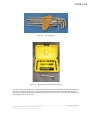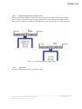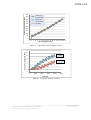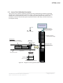
1
GTR9-3-04
Flex PLI GTR
User Manual
133-9900 User Manual FLEX PLI GTR Rev C
©2011 Humanetics Innovative Solutions
Page 1 of 79
GTR9-3-04
For information on Humanetics products, please visit our web site at www.humaneticsatd.com or contact:
Humanetics Innovative Solutions
47460 Galleon Drive
Plymouth, MI 48170, USA
Telephone: 734-451-7878
Fax: 734-451-9549
No part of this publication may be reproduced, stored in a retrieval system or transmitted in any form or
by any means, electronic, photocopying, recording, mechanical or otherwise, without the express written
consent of Humanetics Innovative Solutions.
Copyright © 2011 Humanetics Innovative Solutions. All rights reserved.
The information in this manual is furnished for informational use only, and is subject to change without
notice. Humanetics Innovative Solutions. assumes no responsibility or liability for any errors or
inaccuracies that may appear in this manual.
133-9900 User Manual FLEX PLI GTR Rev C
©2011 Humanetics Innovative Solutions
Page 2 of 79
GTR9-3-04
Table of Contents
Section 1.
Introduction ............................................................................................................................. 8
1.1
Overview ......................................................................................................................................... 8
1.2
Tools Required ............................................................................................................................... 9
Section 2.
Instrumentation...................................................................................................................... 12
2.1
Standard 12 Channel instrumentation ........................................................................................... 12
2.2
Optional instrumentation ............................................................................................................... 12
2.3
ISO MME Codes ........................................................................................................................... 18
2.3.1
Co-ordinate System .............................................................................................................. 21
2.3.2
Signal Polarity, Sensor function check ................................................................................. 22
2.3.3
Filter Class ........................................................................................................................... 22
2.4
Data Acquisition Options ............................................................................................................... 23
2.5
Off Board DAS .............................................................................................................................. 23
2.6
Messring M=BUS On Board Data Acquisition ............................................................................... 25
2.6.1
M=BUS description............................................................................................................... 25
2.6.2
24 Channel M=BUS.............................................................................................................. 28
2.7
DTS Onboard SLICE Nano DAS................................................................................................... 30
2.8
SLICE 24 Channel Option ............................................................................................................. 34
Section 3.
3.1
Assembly and Disassembly ................................................................................................... 35
Femur Exploded View ................................................................................................................... 37
3.1.1.
Femur (Upper Leg) Assembly .............................................................................................. 39
3.1.2.
Femur after Calibration ......................................................................................................... 42
3.1.3.
Femur Disassembly .............................................................................................................. 42
3.2
Knee Exploded View ..................................................................................................................... 43
3.2.1.
Knee Assembly .................................................................................................................... 44
3.2.2.
After Calibration.................................................................................................................... 47
3.2.3.
Knee Disassembly ................................................................................................................ 47
3.3
Tibia Exploded View ..................................................................................................................... 49
3.3.1.
Tibia Assembly ..................................................................................................................... 51
133-9900 User Manual FLEX PLI GTR Rev C
©2011 Humanetics Innovative Solutions
Page 3 of 79
GTR9-3-04
3.3.2.
After Calibration: ................................................................................................................... 53
3.3.3.
Tibia Disassembly ................................................................................................................ 53
3.3.4.
Leg Assembly ....................................................................................................................... 53
3.3.5.
Leg Disassembly .................................................................................................................. 56
Section 4.
Weight Specification .............................................................................................................. 57
Section 5.
Calibration and certification testing ........................................................................................ 58
5.1
Overview ....................................................................................................................................... 58
5.2
Femur and Tibia Bone Assembly Certification .............................................................................. 59
5.2.1
Introduction ................................................................................................................................... 59
5.2.2
Femur and Tibia assembly Certification ........................................................................................ 59
5.3
Knee Calibration ........................................................................................................................... 62
5.4
Pendulum Dynamic Calibration ..................................................................................................... 64
5.5
Leg Preparation for Pendulum Dynamic Calibration ..................................................................... 66
Section 6.
Leg Preparation for Dynamic Inverse Test ............................................................................ 69
6.1
Introduction ................................................................................................................................... 69
6.2
Leg Preparation for Dynamic Inverse Test .................................................................................... 69
6.3
Inverse Test Calibration Description ............................................................................................. 71
6.3.1.
Requirements ....................................................................................................................... 72
6.3.1.1. Impactor ............................................................................................................................... 72
6.3.1.2. Temperature ......................................................................................................................... 72
6.3.1.3. Impactor Pitch, Roll and Yaw angle corridor ......................................................................... 72
6.3.1.4. Flex PLI Inverse Test Corridor .............................................................................................. 72
6.4
Car Test ........................................................................................................................................ 73
Section 7.
Impactor Guide setting distance on Launcher ....................................................................... 74
Section 8.
Dynamic Rig .......................................................................................................................... 76
133-9900 User Manual FLEX PLI GTR Rev C
©2011 Humanetics Innovative Solutions
Page 4 of 79
GTR9-3-04
Table of Figures
Figure 1 .
T-Handle Wrenches............................................................................................................. 9
Figure 2 .
Hex Wrenches ................................................................................................................... 10
Figure 3 .
Ratchet offset wrench with hex bits kit ............................................................................... 10
Figure 4 .
Leg wire setting tool 133-5112........................................................................................... 11
Figure 5 .
Knee spacer tool 133-5113, 2 are used to hold string potentiometer attachment plate ...... 11
Figure 6 .
Optional Instrumentation, for Femur .................................................................................. 13
Figure 7 .
Detail A, Exploded View .................................................................................................... 14
Figure 8 .
Wire routing for Detail A optional sensors .......................................................................... 14
Figure 9 .
Wire routing out of segment for optional sensors Detail A in upper knee ........................... 15
Figure 10 .
Similar arrangement to Detail A but with 2 uniax Kyowa accels. Assembly 133-7600 ....... 15
Figure 11 .
Sensor IES 3103 ARS triax for Knee upper and lower used with M=BUS, (mount 133-7522)
.......................................................................................................................................... 16
Figure 12 .
Kyowa accel 3 axis option for leg top and bottom locations, (mount 133-7530) ................. 16
Figure 13 .
Optional Instrumentation, for Tibia ..................................................................................... 17
Figure 14 .
Leg Local Sign Convention ................................................................................................ 21
Figure 15 .
Leg manipulations for positive output ................................................................................ 22
Figure 16 .
Clamping Arrangement and Position for Off board Wires .................................................. 23
Figure 17 .
Off Board DAS wiring left hand side of impact face ........................................................... 24
Figure 18 .
Off Board DAS wiring right hand side of impact face ......................................................... 24
Figure 19 .
Wiring Diagram for 12 channel M=BUS ............................................................................. 25
Figure 20 .
M=BUS wiring arrangement in knee .................................................................................. 26
Figure 21 .
Clamping of Messring Disconnect Connector .................................................................... 26
Figure 22 .
Messring Terminator housing installation in upper knee .................................................... 27
Figure 23 .
Fixing Messring Wire to Launcher ..................................................................................... 27
Figure 24 .
Right hand side of knee, sensors not connected ............................................................... 28
Figure 25 .
Top right hand side of knee sensors connected ................................................................ 28
Figure 26 .
Bottom right hand side of knee sensors connected ........................................................... 29
Figure 27 .
Top left hand side of knee sensors connected................................................................... 29
Figure 28 .
Bottom left hand side of knee sensors connected ............................................................. 30
Figure 29 .
Wiring diagram for 12 channel SLICE................................................................................ 31
Figure 30 .
Typical Slice wiring to knee with SLICE ............................................................................. 31
Figure 31 .
Disconnect connector and clamp on leg ............................................................................ 32
Figure 32 .
Left hand side of leg with knee covers fitted. Leg wires are not shown secured ................ 32
Figure 33 .
Right hand side of knee showing earth strap terminations and connectors ....................... 33
Figure 34 .
Leg with disconnect wire, TDAS interface and power supply ............................................. 33
133-9900 User Manual FLEX PLI GTR Rev C
©2011 Humanetics Innovative Solutions
Page 5 of 79
GTR9-3-04
Figure 35 .
Optional SLICE unit 24 channel option (right side) ............................................................ 34
Figure 36 .
Left side wiring example of 24 channel SLICE................................................................... 34
Figure 37 .
Instrumented Leg, Exploded View ..................................................................................... 35
Figure 38 .
Femur Assembly, Exploded View ...................................................................................... 37
Figure 39 .
Femur bone assembly ....................................................................................................... 39
Figure 40 .
Fitting end shims in femur ................................................................................................. 40
Figure 41 .
Passing segment over bone wire ....................................................................................... 40
Figure 42 .
Exit wire from femur........................................................................................................... 41
Figure 43 .
Exit cable restraint use cable ties (tie not shown trimmed) ................................................ 42
Figure 44 .
Knee Assembly, Exploded View ........................................................................................ 43
Figure 45 .
Meniscus string pot assembly wire feed ............................................................................ 45
Figure 46 .
Meniscus with all string pots assembled. String pots identified .......................................... 45
Figure 47 .
Meniscus wire clamp ......................................................................................................... 46
Figure 48 .
Attachment plate ready, crimp wires in tension for knee femur block assembly................. 47
Figure 49 .
Cross wire feed through on knee ....................................................................................... 47
Figure 50 .
Tibia Assembly, Exploded View......................................................................................... 49
Figure 51 .
Typical shim arrangement with .05 inside main shim ......................................................... 52
Figure 52 .
Screws to be tightened to 8 Nm......................................................................................... 53
Figure 53 .
Assembly of first flesh layer ............................................................................................... 54
Figure 54 .
Assembly of flesh second layer ......................................................................................... 55
Figure 55 .
Rubber flesh assembly Velcro positions ............................................................................ 55
Figure 56 .
Rubber flesh tied on with Velcro ........................................................................................ 55
Figure 57 .
Leg with outer cover fitted.................................................................................................. 56
Figure 58 .
Bone Assembly Fixture ( tibia shown )............................................................................... 60
Figure 59 .
Knee Calibration Fixture .................................................................................................... 62
Figure 60 .
Diagram of Dynamic Pendulum Fixture ............................................................................. 64
Figure 61 .
Release Latch Wire Position.............................................................................................. 65
Figure 62 .
Attaching Ballast Weight .................................................................................................... 66
Figure 63 .
Step 3 Attaching Dynamic Rig Pivot Block ........................................................................ 67
Figure 64 .
Screws to be torqued to 8 Nm ........................................................................................... 69
Figure 65 .
Stop cable clearance adjustment using setting tool ........................................................... 70
Figure 66 .
Diagram of Inverse guided impactor Certification .............................................................. 71
Figure 67 .
Optional catch rope bracket 133-5034 ............................................................................... 73
Figure 68 .
Impactor guide width setting 113mm ................................................................................. 74
Figure 69 .
Location of impactor guide on pusher (launch plate) JARI pusher shown as example ...... 75
Figure 70 .
Exploded view Dynamic Rig .............................................................................................. 77
133-9900 User Manual FLEX PLI GTR Rev C
©2011 Humanetics Innovative Solutions
Page 6 of 79
GTR9-3-04
Table List
Table 1.
Contents of the tool kit provided with the leg on delivery. ...................................................... 11
Table 2.
12 Channel Instrumentation .................................................................................................. 12
Table 3.
Example of Optional Instrumentation Parts List ..................................................................... 17
Table 4.
ISO MME Sensor Code table ................................................................................................ 20
Table 5.
Wire label codes for all sensors ............................................................................................. 21
Table 6.
Flex PLI Parts List ................................................................................................................. 36
Table 7.
Femur Assembly, Parts List ................................................................................................... 38
Table 8.
Knee Assembly, Parts List..................................................................................................... 44
Table 9.
Tibia Assembly, Parts List ..................................................................................................... 50
Table 10.
Flex PLI GTR Mass ........................................................................................................... 57
Table 11.
Sensor Mass Breakdown ................................................................................................... 57
Table 12.
FLEX-PLI-GTR certification steps ...................................................................................... 58
Table 13.
Femur assembly calibration corridor showing a typical result ............................................ 60
Table 14.
Tibia assembly calibration corridor showing a typical result ............................................... 61
Table 15.
Figure MCL sensor elongation corridor .............................................................................. 63
Table 16.
Figure ACL and PCL corridors ........................................................................................... 63
Table 17.
Draft GTR 9 Regulation Pendulum test corridors; values are up to 250 ms after impact. .. 67
Table 18.
Draft non injurious Pendulum test corridors: values are up to 250 ms after impact............ 68
Table 19.
Dynamic Inverse test corridors. These peak values shall be within 50 ms after impact ..... 72
Table 20.
Dynamic Rig Part List ........................................................................................................ 78
133-9900 User Manual FLEX PLI GTR Rev C
©2011 Humanetics Innovative Solutions
Page 7 of 79
GTR9-3-04
Section 1. Introduction
1.1 Overview
Pedestrian Lower Legform Impactors are used to evaluate pedestrian protection afforded by passenger
cars in case of vehicle collision with a pedestrian. The current EEVC WG17 Pedestrian lower legform
impactor is known to have certain limitations regarding the biofidelity and the repeatability of the test
results. Therefore, Japan proposed to use a completely new legform, the so-called Flexible Pedestrian
Legform Impactor (FlexPLI). In the year 2000, the Japan Automobile Manufacturers Association, Inc.
(JAMA) and the Japan Automobile Research Institute (JARI) initiated development of the “Flexible
Pedestrian Leg form Impactor (Flex-PLI)”. In 2002, an initial design was made available, followed by the
Flex-GT version in 2006. The FLEX-PLI features biomechanically based femur, tibia and knee design,
with biofidelic bending characteristics. In the knee the ligaments are represented according to human
anthropometry. A Technical Evaluation Group (FLEX-TEG), consisting of governmental and industrial
parties, is evaluating the possibility to use the leg form impactor for Global Technical Regulation on
Pedestrian Safety (PS-GTR). FTSS is a member of this group as dummy manufacturer. FTSS was asked
to review the GT design and manufacture the leg. This review highlighted a number of improvements and
the proposed GTR design was accepted. The performance of the leg was intended to remain the same to
ensure existing test data was still valid.
The main improvements were centralising the deflection sensors to avoid impact direction sensitivity,
balancing the spring force load in the knee joint to prevent knee joint twist about vertical axis, various
improvements related to handling, introduction of full bridge strain gauge configuration, adding additional
optional sensors and incorporating on board Data Acquisition System (DAS) to improve free flight motion.
FTSS also reviewed and updated the numerous quasi static calibration procedures for internal bones,
thigh, knee and lower leg assemblies. The dynamic calibration rig and procedure were also updated to
provide more realistic loading. An inverse linear guided impactor test will be required as an additional
dynamic calibration method
The standard leg instrumentation has 12 channels; this includes 3 full bridge strain gage sensors in the
thigh and 4 in the lower leg all measuring leg bending moment, an accelerometer and 4 string
potentiometers in the knee, each one measures specific ligament elongation. There are also options for a
further 26 linear accelerometer channels and 6 Angular Rate Sensors (ARS).
Flex GTR has symmetric design so can represent a right or left leg.
133-9900 User Manual FLEX PLI GTR Rev C
©2011 Humanetics Innovative Solutions
Page 8 of 79
GTR9-3-04
1.2 Tools Required
Several types of standard tools are used in the assembly and disassembly of the dummy. T-handle
wrenches (Figure 1) and hex wrenches (Figure 2) can be used to access most of the fasteners in the
dummy. In some cases, access to fasteners is easier if a ratchet offset wrench with hex bits is used
(Figure 3).
Figure 1 .
133-9900 User Manual FLEX PLI GTR Rev C
©2011 Humanetics Innovative Solutions
T-Handle Wrenches
Page 9 of 79
GTR9-3-04
Figure 2 .
Figure 3 .
Hex Wrenches
Ratchet offset wrench with hex bits kit
8, 4 mm and 1/8”open ended wrenches are required along with 8mm socket and ratchet. Wire spacer tool
133-5112 is required see Figure 4 to help set bone assembly wires and there is another spacer tool to
space the knee string potentiometer attachment part 133-5113 See Figure 5. All these tools are provided
with the leg as part of the tool box.
133-9900 User Manual FLEX PLI GTR Rev C
©2011 Humanetics Innovative Solutions
Page 10 of 79
GTR9-3-04
Figure 4 .
Figure 5 .
Leg wire setting tool 133-5112
Knee spacer tool 133-5113, 2 are used to hold string potentiometer attachment plate
Note: Apart from the string potentiometer #2-56 UNC cap head screws and the ARS optional angular rate
sensors which use #0-80 cap heads all the leg screws are metric.
QTY
1
25 meter roll
20
1
1
1
2
10
Table 1.
PART NO.
6002565
6002558-13
5000522
133-5112
5000819
9003192
133-5113
133-5025
DESCRIPTION
Transport Case
Double Sided Tape, 50mm Wide
M5 Nyloc Nuts
Wire Setting Tool
Open Ended Wrench, 4mm
Open Ended Wrench, 1/8”
Setting Tool, Knee
Double Sided Tape, Impact Segment
Contents of the tool kit provided with the leg on delivery.
A strong double sided tape supplied by Teraoke is used extensively on the Flex leg. FTSS
recommends the use of this tape or a tape with the same strength to maintain performance.
133-9900 User Manual FLEX PLI GTR Rev C
©2011 Humanetics Innovative Solutions
Page 11 of 79
GTR9-3-04
Section 2. Instrumentation
2.1
Standard 12 Channel instrumentation
FLEX-PLI-GTR is offered with 12 channel standard instrumentation, measuring tibia and femur bending
moments and knee ligament elongations as well as tibia acceleration in impact direction. The standard
instrumentation channels are listed in Table 2. The channels intended for injury assessment are tibia
bending moments and knee medial collateral ligament (MCL) elongation. These channels are controlled
by the certification procedures given in Section 5.
Instrument Channels
Femur moment 1,2 and 3
Purpose
Injury
Assessment
Injury
Assessment
Tibia moment 1,2,3 and 4
Tibia top acceleration ax
MCL elongation
ACL elongation
Monitoring
Monitoring
Total
PCL elongation
LCL elongation
Table 2.
2.2
Standard
3
DAS
4
1
1
Standard Option
iDummy
1
1
1
12
12 Channel Instrumentation
Optional instrumentation
The FLEX-PLI offers a range of optional instrumentation for research purpose. When running regulatory
tests with optional instrumentation, it is recommended to check that the total mass of the tool, including a
certain amount of cable length, does not exceed the regulatory requirement. Each individual femur and
tibia segment can be instrumented with an accelerometer in impact direction. Tri-axial accelerometers
and/or angular rate sensors are also offered at various locations. It is recommended that damped
accelerometers are used on the flex.
133-9900 User Manual FLEX PLI GTR Rev C
©2011 Humanetics Innovative Solutions
Page 12 of 79
GTR9-3-04
Figure 6 .
133-9900 User Manual FLEX PLI GTR Rev C
©2011 Humanetics Innovative Solutions
Optional Instrumentation, for Femur
Page 13 of 79
GTR9-3-04
Figure 7 .
Figure 8 .
Detail A, Exploded View
Wire routing for Detail A optional sensors
133-9900 User Manual FLEX PLI GTR Rev C
©2011 Humanetics Innovative Solutions
Page 14 of 79
GTR9-3-04
Figure 9 .
Wire routing out of segment for optional sensors Detail A in upper knee
Figure 10 . Similar arrangement to Detail A but with 2 uniax Kyowa accels. Assembly 133-7600
133-9900 User Manual FLEX PLI GTR Rev C
©2011 Humanetics Innovative Solutions
Page 15 of 79
GTR9-3-04
Sensor IES 3103 ARS triax for Detail A position used with M=BUS. A single uniax accel either a Kyowa
ASE-500 or MSI model 64 or similar can also be used here with this sensor. Assembly 133-7522, Figure
11. Figure 12 shows Kyowa accelerometer option for femur top and tibia bottom locations.
Figure 11 . Sensor IES 3103 ARS triax for Knee upper and lower used with M=BUS, (mount 133-7522)
Figure 12 . Kyowa accel 3 axis option for leg top and bottom locations, (mount 133-7530)
133-9900 User Manual FLEX PLI GTR Rev C
©2011 Humanetics Innovative Solutions
Page 16 of 79
GTR9-3-04
Figure 13 .
ITEM
1
2
2
3
4
5
6
7
8
QTY
1
6
8
1
1
1
1
3
6
PART NO.
133-7508
133-7514
133-7514
133-7507
133-7502
133-7516
5000164
IT-TBD
9003103
9
1
MS-68C
10
1
133-7506
Optional Instrumentation, for Tibia
DESCRIPTION
ACCEL INSTRUMENTED OPTION LEG TOP & BOTTOM
IMPACT SEGMENT - INSTRUMENTED ASSEMBLY (FEMUR)
IMPACT SEGMENT - INSTRUMENTED ASSEMBLY (TIBIA)
ACCEL & ARS INSTRUMENTED OPTION FOR KNEE
KNEE END ACCEL MOUNT
TAPE, DOUBLE SIDED
SCREW, SHCS M2 X 0.4 X 18
DTS ANGULAR RATE SENSOR
SCREW, SHCS #0-80 X 5/16
ACCELEROMETER, LINEAR TRIAXIAL, MEASUREMENT
SPECIALTIES MS 68C
SPECIAL M2 ACCEL FIXING
Table 3.
Example of Optional Instrumentation Parts List
133-9900 User Manual FLEX PLI GTR Rev C
©2011 Humanetics Innovative Solutions
Page 17 of 79
GTR9-3-04
2.3
ISO MME Codes
For the identification of sensor channels and for computer processing of signals the following codes have
been established for ISO MME.
No.
1
2
3
4
5
6
7
8
9
10
11
12
13
14
15
16
17
18
19
20
Location
(Description)
Femur
Moment 3
Upper, X
Femur
Moment 2
Middle, X
Femur
Moment 1
Lower, X
Knee LCL
Elongation
Knee ACL
Elongation
Knee PCL
Elongation
Knee MCL
Elongation
Tibia Moment
1 Upper, X
Tibia Moment
2 Middle
Upper, X
Tibia Moment
3 Middle
Lower, X
Tibia Moment
4 Lower, X
Knee Bottom
Acceleration,
Y
Femur Top
Acceleration,
X
Femur Top
Acceleration,
Y
Femur Top
Acceleration,
Z
Femur
Segment 1
Acceleration,
Y
Femur
Segment 2
Acceleration,
Y
Femur
Segment 3
Acceleration,
Y
Femur
Segment 4
Acceleration,
Y
Femur
Segment 5
Acceleration,
Y
Category
Test
Object
Position
Transd
Main
Location
Fine
Location
1
Fine
Location
2
Fine
Location
3
Physical
Dimension
Direction
Filter
Class
standard
0
0
FEMR
UP
00
PF
MO
X
C
standard
0
0
FEMR
MI
00
PF
MO
X
C
standard
0
0
FEMR
LO
00
PF
MO
X
C
standard
0
0
KNEE
LC
00
PF
DS
Z
C
standard
0
0
KNEE
AC
00
PF
DS
Z
C
standard
0
0
KNEE
PC
00
PF
DS
Z
C
standard
0
0
KNEE
MC
00
PF
DS
Z
C
standard
0
0
TIBI
UP
00
PF
MO
X
C
standard
0
0
TIBI
MI
UP
PF
MO
X
C
standard
0
0
TIBI
MI
LO
PF
MO
X
C
standard
0
0
TIBI
LO
00
PF
MO
X
C
standard
0
0
KNEE
BO
00
PF
AC
Y
C
additional
0
0
FEMR
TP
00
PF
AC
X
C
additional
0
0
FEMR
TP
00
PF
AC
Y
C
additional
0
0
FEMR
TP
00
PF
AC
Z
C
additional
0
0
FEMR
01
00
PF
AC
Y
C
additional
0
0
FEMR
02
00
PF
AC
Y
C
additional
0
0
FEMR
03
00
PF
AC
Y
C
additional
0
0
FEMR
04
00
PF
AC
Y
C
additional
0
0
FEMR
05
00
PF
AC
Y
C
133-9900 User Manual FLEX PLI GTR Rev C
©2011 Humanetics Innovative Solutions
Page 18 of 79
GTR9-3-04
21
22
23
24
25
26
27
28
29
30
31
32
33
34
35
36
37
38
39
40
41
Femur
Segment 6
Acceleration,
Y
Knee Upper
Acceleration,
X
Knee Upper
Acceleration,
Y
Knee Upper
Acceleration,
Z
Knee Upper
Angular Rate,
X
Knee Upper
Angular Rate,
Y
Knee Upper
Angular Rate,
Z
Knee Lower
Acceleration,
X
Knee Lower
Acceleration,
Y
Knee Lower
Acceleration,
Z
Knee Lower
Angular Rate,
X
Knee Lower
Angular Rate,
Y
Knee Lower
Angular Rate,
Z
Tibia Segment
1
Acceleration,
Y
Tibia Segment
2
Acceleration,
Y
Tibia Segment
3
Acceleration,
Y
Tibia Segment
4
Acceleration,
Y
Tibia Segment
5
Acceleration,
Y
Tibia Segment
6
Acceleration,
Y
Tibia Segment
7
Acceleration,
Y
Tibia Segment
8
Acceleration,
Y
additional
0
0
FEMR
06
00
PF
AC
Y
C
additional
0
0
KNEE
UP
00
PF
AC
X
C
additional
0
0
KNEE
UP
00
PF
AC
Y
C
additional
0
0
KNEE
UP
00
PF
AC
Z
C
additional
0
0
KNEE
UP
00
PF
AV
X
C
additional
0
0
KNEE
UP
00
PF
AV
Y
C
additional
0
0
KNEE
UP
00
PF
AV
Z
C
additional
0
0
KNEE
LO
00
PF
AC
X
C
additional
0
0
KNEE
LO
00
PF
AC
Y
C
additional
0
0
KNEE
LO
00
PF
AC
Z
C
additional
0
0
KNEE
LO
00
PF
AV
X
C
additional
0
0
KNEE
LO
00
PF
AV
Y
C
additional
0
0
KNEE
LO
00
PF
AV
Z
C
additional
0
0
TIBI
01
00
PF
AC
Y
C
additional
0
0
TIBI
02
00
PF
AC
Y
C
additional
0
0
TIBI
03
00
PF
AC
Y
C
additional
0
0
TIBI
04
00
PF
AC
Y
C
additional
0
0
TIBI
05
00
PF
AC
Y
C
additional
0
0
TIBI
06
00
PF
AC
Y
C
additional
0
0
TIBI
07
00
PF
AC
Y
C
additional
0
0
TIBI
08
00
PF
AC
Y
C
133-9900 User Manual FLEX PLI GTR Rev C
©2011 Humanetics Innovative Solutions
Page 19 of 79
GTR9-3-04
42
43
44
Tibia Bottom
Acceleration,
X
Tibia Bottom
Acceleration,
Y
Tibia Bottom
Acceleration,
Z
additional
0
0
TIBI
BO
00
PF
AC
X
C
additional
0
0
TIBI
BO
00
PF
AC
Y
C
additional
0
0
TIBI
BO
00
PF
AC
Z
C
Table 4.
Location (Description)
Femur Moment 3 Upper, X
Femur Moment 2 Middle, X
Femur Moment 1 Lower, X
Knee LCL Elongation
Knee ACL Elongation
Knee PCL Elongation
Knee MCL Elongation
Tibia Moment 1 Upper, X
Tibia Moment 2 Middle Upper, X
Tibia Moment 3 Middle Lower, X
Tibia Moment 4 Lower, X
Knee Bottom Acceleration, Y
Femur Top Acceleration, X
Femur Top Acceleration, Y
Femur Top Acceleration, Z
Femur Segment 1 Acceleration, Y
Femur Segment 2 Acceleration, Y
Femur Segment 3 Acceleration, Y
Femur Segment 4 Acceleration, Y
Femur Segment 5 Acceleration, Y
Femur Segment 6 Acceleration, Y
Knee Upper Acceleration, X
Knee Upper Acceleration, Y
Knee Upper Acceleration, Z
Knee Upper Angular Rate, X
Knee Upper Angular Rate, Y
Knee Upper Angular Rate, Z
Knee Lower Acceleration, X
Knee Lower Acceleration, Y
Knee Lower Acceleration, Z
Knee Lower Angular Rate, X
Knee Lower Angular Rate, Y
Knee Lower Angular Rate, Z
Tibia Segment 1 Acceleration, Y
Tibia Segment 2 Acceleration, Y
Tibia Segment 3 Acceleration, Y
Tibia Segment 4 Acceleration, Y
Tibia Segment 5 Acceleration, Y
Tibia Segment 6 Acceleration, Y
ISO MME Sensor Code table
Wire Label
Code
F3
F2
F1
LCL
ACL
PCL
MCL
T1
T2
T3
T4
AY-KB
AX-FT
AY-FT
AZ-FT
AY-S1
AY-S2
AY-S3
AY-S4
AY-S5
AY-S6
AX-KU
AY-KU
AZ-KU
ARX-KU
ARY-KU
ARZ-KU
AX-KL
AY-KL
AZ-KL
ARX-KL
ARY-KL
ARZ-KL
AY-S7
AY-S8
AY-S9
AY-S10
AY-S11
AY-S12
133-9900 User Manual FLEX PLI GTR Rev C
©2011 Humanetics Innovative Solutions
TRIAX Sensor
wire label
code
F1-3
T1-3
A-FT
A-KU
AR-KU
A-KL
AR-KL
ISOMMECODE
00FEMRUP00PFMOXC
00FEMRMI00PFMOXC
00FEMRLO00PFMOXC
00KNEELC00PFDSZC
00KNEEAC00PFDSZC
00KNEEPC00PFDSZC
00KNEEMC00PFDSZC
00TIBIUP00PFMOXC
00TIBIMIUPPFMOXC
00TIBIMILOPFMOXC
00TIBILO00PFMOXC
00KNEEBO00PFCAYC
00FEMRTP00PFACXC
00FEMRTP00PFACYC
00FEMRTP00PFACZC
00FEMR0100PFACYC
00FEMR0200PFACYC
00FEMR0300PFACYC
00FEMR0400PFACYC
00FEMR0500PFACYC
00FEMR0600PFACYC
00KNEEUP00PFACXC
00KNEEUP00PFACYC
00KNEEUP00PFACZC
00KNEEUP00PFAVXC
00KNEEUP00PFAVYC
00KNEEUP00PFAVZC
00KNEELO00PFACXC
00KNEELO00PFACYC
00KNEELO00PFACZC
00KNEELO00PFAVXC
00KNEELO00PFAVYC
00KNEELO00PFAVZC
00TIBI0100PFACYC
00TIBI0200PFACYC
00TIBI0300PFACYC
00TIBI0400PFACYC
00TIBI0500PFACYC
00TIBI600PFACYC
Page 20 of 79
GTR9-3-04
Tibia Segment 7 Acceleration, Y
Tibia Segment 8 Acceleration, Y
Tibia Bottom Acceleration, X
Tibia Bottom Acceleration, Y
Tibia Bottom Acceleration, Z
Table 5.
2.3.1
AY-S13
AY-S14
AY-TB
AY-TB
AZ-TB
A-TB
00TIBI0700PFACYC
00TIBI0800PFACYC
00TIBIBO00PFACXC
00TIBIBO00PFACYC
00TIBIBO00PFACZC
Wire label codes for all sensors
Co-ordinate System
Recommended local co-ordinate system for standardization.
Figure 14 . Leg Local Sign Convention
133-9900 User Manual FLEX PLI GTR Rev C
©2011 Humanetics Innovative Solutions
Page 21 of 79
GTR9-3-04
2.3.2
Signal Polarity, Sensor function check
The leg can be pushed manually as shown in Figure 15 below to test polarity and function for positive
output. A spacer can be placed under the leg to assist in the bending of the leg. The positive outputs
shown in Figure 15 below are preferred for standardization; users can use their own polarity if required.
Figure 15 . Leg manipulations for positive output
2.3.3
Filter Class
The filter class CFC to be used on the Flex PLI is 180.
133-9900 User Manual FLEX PLI GTR Rev C
©2011 Humanetics Innovative Solutions
Page 22 of 79
GTR9-3-04
2.4
Data Acquisition Options
The FLEX PLI can be used with various options for data acquisition systems. The most basic version is a
system with connection cables to a static laboratory Data Acquisition System (DAS), the so called offboard DAS option. As the FLEX-PLI is a tool that is in free flight after launch, the off board cables may
affect the free flight trajectory accuracy and the cables are susceptible to damage when the tool lands
after rebound from the vehicle. Therefore the use of off board DAS is only recommended during
calibration of the FLEX-PLI. To solve issues with free flight trajectory and cable damage, the FLEX-PLIGTR can be executed with on board DAS systems from various suppliers. Currently FTSS is working in
close co-operation with and offering systems from Messring, DTS, Hentschel and Kayser-Threde. The
Messring and DTS systems are described in 2.6 and 2.7.
2.5
Off Board DAS
For off board DAS umbilical cables of 10m long exit the leg just below the knee. This position is close to
the CG of the leg to minimize the mass affect from the cables in free flight. The cables are clamped to the
leg via the top shoulder link bolts of the tibia to provide restraint protection to the connectors see Figure
16. See Figure 17 for left hand side wiring arrangement. The connectors at the off board DAS side are
specified by the customer and fitted by FTSS as all users have different systems.
Figure 16 . Clamping Arrangement and Position for Off board Wires
133-9900 User Manual FLEX PLI GTR Rev C
©2011 Humanetics Innovative Solutions
Page 23 of 79
GTR9-3-04
Figure 17 . Off Board DAS wiring left hand side of impact face
Most of the wiring for the off board configuration is in the tibia block. Only the femur bone wire bridges the
knee joint, see Figure 18 for wiring on right hand side.
All the sensors use miniature round connectors with locking latch, either a 7 pin or 16 pin is used.
The 16 pin connectors are for the 3 femur strain gages and for 3 of the 4 tibia strain gages. 16 pin
connectors are also used for optional triaxial accelerometers.
All the sensor wires are identified to ensure correct connection.
Figure 18 . Off Board DAS wiring right hand side of impact face
133-9900 User Manual FLEX PLI GTR Rev C
©2011 Humanetics Innovative Solutions
Page 24 of 79
GTR9-3-04
The leg wires must be balanced to ensure good free flight after launch with 6 channels each side. On the
right side are 2 single channel string pots, 1 single channel accelerometer and 1 three channel wire for
the three femur bone gages. On the left side there are 2 single channel string pots, 1 single channel tibia
bone gage and 1 three channel wire for the other tibia bone gages.
It is important to route the off board cables out of the knee to ensure good free flight to the target. See
Figure 14 for an example. Users can establish there own wire routing but the important issues to note are
that both sides are balanced and there is no restriction at release from the pusher plate when fired.
2.6
Messring M=BUS On Board Data Acquisition
2.6.1 M=BUS description
An overview of the M=BUS system is shown in Figure 19. The M=BUS is a 6 channel logger fitted inside
a magnesium housing; connection is made to the logger via a plug in PCB board. For the standard 12
channels there are two M=BUS units one either side of the knee, three M3 FHCS fix the units to the knee.
The sensor connection is made by either a 7 pin or 16 pin miniature round connector with locking latch.
For M=BUS left hand side of leg see Figure 20. For detailed use and specifications please refer to the
suppliers user instructions.
Figure 19 . Wiring Diagram for 12 channel M=BUS
For leg wire routing please refer to Figure 20 below, this is typical for both sides.
133-9900 User Manual FLEX PLI GTR Rev C
©2011 Humanetics Innovative Solutions
Page 25 of 79
GTR9-3-04
The disconnect wire is a blue coax cable, the brass end fitting is clamped to one of the off board cable
clamps just below the knee see Figure 21. This direct clamping avoids any damage to the connector. Be
careful not to crush the connector when clamping. Only one cable clamp requires fitting for Messring
installation. A hole also has to be cut in the outer cover to allow exit of the cable.
After the test the disconnect is reconnected and data can be downloaded to a PC.
Inside the femur block there is a terminator housing to complete the coax wiring, see Figure 22, two
M3 SHCS retain the part. The terminator can only be accessed when the knee is disassembled. If the
knee is stripped down for access it is recommended the knee is recalibrated.
The loggers are programmed to specific sensors for sensitivity, range and software recognition. Loggers
cannot change location and connector labels must match to ensure connection to the sensor.
Figure 20 . M=BUS wiring arrangement in knee
Figure 21 . Clamping of Messring Disconnect Connector
133-9900 User Manual FLEX PLI GTR Rev C
©2011 Humanetics Innovative Solutions
Page 26 of 79
GTR9-3-04
Figure 22 . Messring Terminator housing installation in upper knee
Figure 23, shows the M=BUS disconnect wire on the launcher and how the coax wire is routed and fixed
to the launcher. The disconnect design has a low release force, however a strong tape is recommended
to hold the wire in place, see Figure 23.
Figure 23 . Fixing Messring Wire to Launcher
133-9900 User Manual FLEX PLI GTR Rev C
©2011 Humanetics Innovative Solutions
Page 27 of 79
GTR9-3-04
2.6.2 24 Channel M=BUS
Four, six channel loggers can be fitted to the leg to provide 24 channels of data recording. See figures
below for typical installation. Wire connections can vary according to optional sensors installed.
Figure 24 . Right hand side of knee, sensors not connected
Figure 25 . Top right hand side of knee sensors connected
133-9900 User Manual FLEX PLI GTR Rev C
©2011 Humanetics Innovative Solutions
Page 28 of 79
GTR9-3-04
Figure 26 . Bottom right hand side of knee sensors connected
Figure 27 . Top left hand side of knee sensors connected
133-9900 User Manual FLEX PLI GTR Rev C
©2011 Humanetics Innovative Solutions
Page 29 of 79
GTR9-3-04
Figure 28 . Bottom left hand side of knee sensors connected
2.7
DTS Onboard SLICE Nano DAS
For detailed use and specifications please refer to suppliers user instructions.
The SLICE is a modular system where a 3 channel bridge SLICE can be stacked onto a base SLICE; in
this case one base SLICE handles 12 channels of data. As the FLEX-PLI has limited space to package
the SLICE stack a mounting board has been designed by DTS to link four bridges together allowing one
base SLICE to be used. The unit is fixed using four M3 pozi head screws. Sensor connection to the DAS
is via either 7 or 16 pin round miniature connectors see Figure 30 for 12 channel wiring arrangement.
After disconnect the SLICE is powered by a Super capacitor mounted on the same side of the knee as
the standard 12 channel DAS See Figure 30. The super capacitor is quickly charged when reconnected.
The wire disconnect is a round 12 pin connector hard mounted to the launch guide bracket at the top of
the femur see Figure 31. This disconnect position allows disconnect in the push phase from the launcher
to avoid the connector affecting free flight stability. On reconnect after the test data can be downloaded to
a PC.
If required there is provision to wire in a tape switch for T=0, a wire is provided for this option out of the
supercap housing.
133-9900 User Manual FLEX PLI GTR Rev C
©2011 Humanetics Innovative Solutions
Page 30 of 79
GTR9-3-04
Figure 29 . Wiring diagram for 12 channel SLICE
Typical Slice wiring to knee with SLICE units, on the right in tibia knee block and super cap on the left in
femur knee block, Figure 30.
Figure 30 . Typical Slice wiring to knee with SLICE
133-9900 User Manual FLEX PLI GTR Rev C
©2011 Humanetics Innovative Solutions
Page 31 of 79
GTR9-3-04
Figure 31 . Disconnect connector and clamp on leg
To assemble the SLICE fit the SLICE unit with the higher stack part closest to the knee joint as shown in
Figure 30 using four M3 Pozi type screws two 25mm and two 20mm long. Then fit the super capacitor
with the disconnect wire pointing downward towards the tibia using four M3 x 16 long screws. All the
connectors are identified so connect like for like, MCL to MCL etc. For the two string pot wires that pass
across the knee tie wrap mounts are provided both sides to anchor the wires, see Figure 33 showing
connectors on the right hand side of the knee. Route the wires as shown to provide adequate slack in the
knee joint to prevent any disconnection or damage to the wires when the knee flexes. The disconnect
bracket is fixed to the launch guide as shown in Figure 31 using M2.5 screws and the 12 pin connector is
mated with the connector coming out of the bottom of the base SLICE. Most of the wires and connectors
are behind the knee covers but the gage wires coming out of the leg must be properly restrained. There
should be two tie wraps fixing the bone gage wires coming out of each bone (tibia and femur) to the end
link where it exits the leg. Before fitting the covers note there are two covers with three holes, one of
these covers part 133-5314 must be fitted over the SLICE unit for screw head clearance as shown in
Figure 32, the other cover 133-5315 is necessary for 24 channel DAS when two SLICE units are fitted. If
24 channels are not being used this cover can go to any of the other three locations.
Figure 32 . Left hand side of leg with knee covers fitted. Leg wires are not shown secured
133-9900 User Manual FLEX PLI GTR Rev C
©2011 Humanetics Innovative Solutions
Page 32 of 79
GTR9-3-04
Figure 33 . Right hand side of knee showing connectors
Figure 34 . Leg with disconnect wire, TDAS interface and power supply
133-9900 User Manual FLEX PLI GTR Rev C
©2011 Humanetics Innovative Solutions
Page 33 of 79
GTR9-3-04
2.8
SLICE 24 Channel Option
To complete the DAS system to 24 channels on board DAS for optional instrumentation, an additional 12
channel SLICE unit is packaged on the opposite side to the standard 12 channel unit in the upper knee
for balance and for access to upper leg sensors to reduce the number of wires crossing the knee joint.
See below. The arrangement of SLICE bridge units and wiring will vary depending on the optional
sensors selected.
Figure 35 . Optional SLICE unit 24 channel option (right side)
Figure 36 . Left side wiring example of 24 channel SLICE
133-9900 User Manual FLEX PLI GTR Rev C
©2011 Humanetics Innovative Solutions
Page 34 of 79
GTR9-3-04
Section 3. Assembly and Disassembly
Figure 37 . Instrumented Leg, Exploded View
133-9900 User Manual FLEX PLI GTR Rev C
©2011 Humanetics Innovative Solutions
Page 35 of 79
GTR9-3-04
ITEM
1
2
3
4
5
6
7
8
9
10
QTY
1
1
1
1
1
1
1
1
1
6
PART NO.
133-5300
133-5500
133-5100
133-5020
133-5013
133-5014
133-5015
133-5016
133-5017
133-5019
DESCRIPTION
KNEE ASSEMBLY, FLEX PLI
TIBIA ASSEMBLY, FLEX PLI
FEMUR ASSEMBLY, FLEX PLI
BUFFER SHEET ASSEMBLY, LEG (NOT SHOWN)
COVER, INNER, FEMUR (NOT SHOWN)
COVER, OUTER, FEMUR (NOT SHOWN)
COVER, INNER, TIBIA (NOT SHOWN)
COVER, OUTER, TIBIA (NOT SHOWN)
COVER, FLEX PLI GTR (NOT SHOWN)
VELCRO BUNDLE TIE, 500mm LONG (NOT SHOWN)
Table 6.
133-9900 User Manual FLEX PLI GTR Rev C
©2011 Humanetics Innovative Solutions
Flex PLI Parts List
Page 36 of 79
GTR9-3-04
3.1
Femur Exploded View
Figure 38 . Femur Assembly, Exploded View
133-9900 User Manual FLEX PLI GTR Rev C
©2011 Humanetics Innovative Solutions
Page 37 of 79
GTR9-3-04
ITEM
1
2
3
4
5
6
7
8
9
10
11
12
13
14
15
16
17
18
19
20
21
22
23
24
25
26
27
28
29
30
31
32
33
34
35
36
37
38
39
40
41
42
43
44
45
QTY
1
1
1
1
1
5
1
1
5
5
1
5
1
28
14
1
1
1
4
16
2
2
1
1
8
4
4
1
6
4
4
2
6
1
4
2
1
1
6
5
2
2
2
5
15
PART NO.
133-5105
133-5508
133-5503
133-5506
133-5502
133-5505
133-5504
133-5510
133-5507
133-5509
133-5514
133-5534
133-5535
5000465
133-5515
133-5108
133-5102
133-5103
133-5104
133-5106
5000094
5000604
5000008
133-5107
133-5521
133-5110
5000522
133-5516
5000072
5000814
5000393
5000769
133-5025
133-5028
133-5027
133-5026
133-5518
133-5519
133-5517
133-5001
133-5002
133-5003
133-5004
133-5005
133-5012
Table 7.
DESCRIPTION
FEMUR BONE ASSEMBLY TESTED & CERTIFIED
BONE CLAMP THIN, KNEE
BONE CLAMP THIN, FEMUR/TIBIA
BONE CLAMP THICK, KNEE
BONE CLAMP THICK, FEMUR/TIBIA
SPACER, BONE CONTACT, THICK
SHIM, BONE CLAMP (.4 THICK) OPTIONAL
RUBBER BUFFER, FEMUR/TIBIA END
SPACER, BONE CONTACT, THIN
SHIM (0.4 THICK) OPTIONAL
INNER SEGMENT, KNEE
INNER SEGMENT ASSEMBLY
INNER SEGMENT ASSEMBLY CLOSES TO KNEE
SCREW, BHCS M6 X 1 X 18
LINK
SEGMENT TOP, FEMUR
PLATE, TOP
LAUNCH GUIDE
WASHER, 12 ID X 26 OD X 3
SHOULDER BOLT
WASHER, FLAT M6 (6.7 ID X 12.5 OD X 1.0 THK.)
SCREW, SHCS M6 X 1 X 14
SCREW, SHCS M6 X 1 X 30
ROLLER
WASHER, CABLE
CABLE ASSEMBLY, FEMUR
HEX NUT, M5 X 0.8 NYLOK
END COVER
SCREW, BHCS M6 X 1 X 16
SCREW BHCS, M5 X .8 X 8
SCREW, SHCS M3 X .5 X 6
SCREW, MSSFP M8 X 16
TAPE, IMPACT SEGMENT
TAPE, END COVER, 12 X 24
TAPE, END COVER, 10 X 12
TAPE, END COVER, 12 X 16
COVER, END IMPACT
COVER, END IMPACT, (KNEE END)
IMPACT SEGMENT
SHIM, (T0-5) OPTIONAL (NOT SHOWN)
SHIM, BONE CLAMP (T0-05) OPTIONAL (NOT SHOWN)
SHIM, BONE CLAMP (T0-5) OPTIONAL (NOT SHOWN)
SHIM, BONE CLAMP (T0-6) OPTIONAL (NOT SHOWN)
SHIM (T0-6) OPTIONAL (NOT SHOWN)
SHIM, (.05) OPTIONAL (NOT SHOWN)
Femur Assembly, Parts List
133-9900 User Manual FLEX PLI GTR Rev C
©2011 Humanetics Innovative Solutions
Page 38 of 79
GTR9-3-04
3.1.1.
Femur (Upper Leg) Assembly
Before assembly check all rubber buffers are bonded to segments. If for any reason a buffer should
become dislodged, damaged or lost it will need re-bonding. When bonding the segment buffers ensure
surfaces of both parts are prepped before bonding, prepare plastic with 240 grit paper and rubber with 80
grit, degrease then bond with Loctite 401 or similar.
Fit thick bone clamp, Item 5 (133-5502) to ‘Segment Top’, Item 16 (133-5108), fit to impact side using two
M6 x 16, BHCS (Black button head cap screw). The difference between thick and thin spacer is 0.5mm
(12.75 thick, 12.25 thin). Place this assembly onto a flat work surface and place the rubber buffer, Item 8
(133-5510) under. Place the bone assembly, Item 1 inside the assembly with the PCB board upper most
on the non impact side and fit the thin bone clamp, Item 3 (133-5503) see Figure 39. Measure the gap
clearance between the thin clamp and the segment wall with metric feeler gauges or use the shims. This
gap must be filled with the shims so that the parts fit as tight as possible See Figure 40 note that by
screwing in two screws the shim will say in place while sizing the gap. Shim thicknesses are 0.05, 0.4, 0.5
and 0.6, use any combination to achieve this fit. Shim part numbers are 133-5002, 5003, 5004 and 5504.
When a good tight fit has been achieved align the holes and fit two M6x16, BHCS (Item 35). The 16mm
long button heads are black to distinguish them for this location from the 18 long ones.
Warning: When fitting the bone clamps and spacers take care not to damage any gage wires or
gages, laid down the center of the bone.
Figure 39 . Femur bone assembly
133-9900 User Manual FLEX PLI GTR Rev C
©2011 Humanetics Innovative Solutions
Page 39 of 79
GTR9-3-04
Figure 40 . Fitting end shims in femur
Select one of the plastic segments, Item 12 (133-5513) which has the best tight fit over the bone clamp,
rubber buffers must interface with the part already fitted, take care not to damage the shims then fit four
M6 x 18 BHCS (Item 14) two each side diagonally spaced.
Note: That the connector will have to pass through each of the segments as they are assembled over the
bone. Do not pull on this wire as the wire is not fully restrained at the PCB mounted on the bone at this
stage. See Figure 41.
Figure 41 . Passing segment over bone wire
Stand the assembly on the bench again over the 2mm buffer and slide a segment assembly over the
bone with the buffers facing down. Fit the thick spacer, Item 6 (133-5505) with radius against the bone to
the front of the segment by pressing gently against the segment this will keep the holes aligned, then fit
two M6 x 18 BHCS diagonally as shown in exploded view. Slide in the thin bone contact spacer, Item 9
(133-5507) in the rear side of the segment with radius against the bone. Shim the part on the rear side to
get the same tight fit as mentioned above. Use shims 133-5001, 5005, 5509 and 5012 to achieve the
133-9900 User Manual FLEX PLI GTR Rev C
©2011 Humanetics Innovative Solutions
Page 40 of 79
GTR9-3-04
required fit. Note: only one 0.4, 0.5 or 0.6mm shim can be assembled; any number of 0.05, 0.1 or 0.2
shims can be used inside the thicker shim to achieve this fit. Align holes and fit the two M6x18, BHCS.
Repeat this procedure for the next five plastic segments. Once a spacer has been shimmed, start the
next segment with the same shim arrangement as a starting point to save time.
The last blue segment Item 13 (133-5535) to be fitted will have rubber buffers on both sides. The
thin spacer and shims will have to be assembled from the underside of the segment due to the
position of the PCB on the bone.
The PCB cable can exit on either side with reference to the impact direction at this point depending on
DAS configuration. Lay the thin bone clamp Item 2 (133-5508) over the PCB as shown in Figure 42. Lay
up the other clamp, Item 4 (133-5506) to the other side and slide over segment knee, Item 11 (133-5514).
Fit two M6x16, BHCS to the front and fit two M8x16, SSFP (Socket set flat point) to the rear so that they
are just touching the clamp. Ensure the buffer 133-5510 is fitted under and centralized, this should be
lightly bonded in place with super glue in case it is disassembled and falls out. Fit the ‘plate top’ Item 17
(133-5102) with four M6x18, BHCS. Pass the connector through a link, Item 15 (133-5515) then
assemble all the links and washers using shoulder screws as shown on assembly both sides. The
segments may need adjusting slightly to fit the shoulder bolts.
Figure 42 . Exit wire from femur
Place washer, Item 26 (133-5521) over each of the four stainless steel cables, Item 27 (133-5110) and
feed through the holes in the leg segments. Place washer (133-5521) over threaded fitting and fit four M5
Nyloc nuts. Set the gap between nut and washer to 9.1mm. Check with spacer tool 133-5112, if nuts are
removed FTSS recommends the Nyloc nuts should only be used twice. Ensure bone clamps are flush
with ends of bone and tighten all segment screws to recommended 2.3-2.5 Nm. Do not over tighten. Fit
one double sided tape profile, Item 34 (133-5025) to the third plastic segment from the knee then fit one
impact segment, Item 40 (133-5517) locating over two BHCS. When fitting double sided tape it would be
good policy to degrease the surfaces.
133-9900 User Manual FLEX PLI GTR Rev C
©2011 Humanetics Innovative Solutions
Page 41 of 79
GTR9-3-04
Where the wire comes out through the link, tie on two cable ties one on the link and one on wire attached
to each other as shown in Figure 43 to provide restraint to the wire. The assembly is now ready for
calibration.
Note: a few of the links, washers and shoulder screws will need to be removed and replaced to fit onto
the calibration fixture. Keep parts together ready for final assembly.
Figure 43 . Exit cable restraint use cable ties (tie not shown trimmed)
3.1.2.
Femur after Calibration
Fit four M3x6, SHCS (Socket head cap screws) into front inner segment knee and segment top. Fit all the
double sided tape profiles and fit impact segments. Fit launch guide and roller as shown in exploded view.
Fit end cover, Item 28 (133-5516) after dynamic calibration with four M5 x 8 screws. Also fit any optional
sensors and mounts.
3.1.3.
Femur Disassembly
Disassembly is the reverse of assembly except you can disassemble from either end, care must be
observed when removing bone spaces and shims not to damage bone wires and gages. The double
sided tape can be reused if still sticky and is not folded over. It will also be important to check for any
damaged parts that would need replacement.
133-9900 User Manual FLEX PLI GTR Rev C
©2011 Humanetics Innovative Solutions
Page 42 of 79
GTR9-3-04
3.2
Knee Exploded View
Figure 44 . Knee Assembly, Exploded View
ITEM
1
2
3
4
5
6
7
8
9
10
QTY
1
1
4
1
1
8
16
16
8
8
PART NO.
133-5330
133-5313
5000774
133-5320
133-5302
9003159
9003158
133-5310
133-5311
133-5350
133-9900 User Manual FLEX PLI GTR Rev C
©2011 Humanetics Innovative Solutions
DESCRIPTION
KNEE BLOCK, TIBIA, FLEX PLI
MENISCUS ASSEMBLY
SCREW, SHCS M5 X .8 X 10, LOWHEAD
KNEE BLOCK, FEMUR
ATTACHMENT PLATE, STRING POT
SPRING, 12 X 40 (AMISTAR DB 12 x 40)
SPRING, 18 X 80 (AMISTAR DB 18 x 80)
SPRING CAP
CABLE WASHER
CABLE ASSEMBLY, KNEE ML
Page 43 of 79
GTR9-3-04
11
12
13
14
15
16
17
18
19
20
21
22
2
1
2
1
16
4
12
4
4
4
1
1
5000203
133-5315
133-5306
133-5314
5000844
133-5360
5000522
5000770
5000850
133-5018
133-5304
133-5305
Table 8.
3.2.1.
SCREW, FHCS M3 X 0.5 X 10
COVER, KNEE, FEMUR RIGHT SIDE
COVER, KNEE
COVER, KNEE, TIBIA LEFT SIDE
SCREW, FHCS M4 X 0.7 X 8, ZINC
AP CABLE ASSEMBLY
HEX NUT, M5 X 0.8 NYLOK
SCREW, MSSFP M8 X 30
SCREW, BHCS M8 X 1.25 X 35, ZINC
TAPE, FRONT COVER
COVER, UPPER KNEE, FLEX PLI
COVER, LOWER KNEE, FLEX PLI
Knee Assembly, Parts List
Knee Assembly
Make a note of the string pot serial numbers and their ligament positions this is needed for off board and
onboard DAS identification for sensitivity input.
Referring to Meniscus assembly Item 2 (133-5313) feed the connector of one of the right hand (RH) pull
string pots through the inner side of one of the central holes, see Figure 45. The RH and the LH string
pots can be identified from the serial number the RH has an R at the end of the number and the LH an L.
The two RH pull string pots are positioned closest to the main flange of the meniscus, one is shown fitted
in Figure 45. Attach the string pot with the #2-56 x ¼ long cap head screws making sure the pull wire is
directed towards the furthest away outer bronze bush. Fit the other RH pull string pot in the same way on
the opposite side. Pass the pull wires through their designated bushes. Carry out the same procedure
with the Left hand pull string pots, the pull wires are directly in line with the two inner bushes. Feed the
pull wires through the bushes. Make sure electrical wires are inside the cavity as much as possible then
run cables through channels both sides and clamp with retaining plate see Figure 47. Fit assembly to
knee block bottom and retain with four M5x10, low head cap screws, ensure wires are in their grooves
before clamping down.
If the Messring on board DAS system is to be installed a terminator has to be fitted at this stage.
For details of onboard DAS installation see Sections 2.6 and 2.7.
133-9900 User Manual FLEX PLI GTR Rev C
©2011 Humanetics Innovative Solutions
Page 44 of 79
GTR9-3-04
Figure 45 . Meniscus string pot assembly wire feed
Figure 46 . Meniscus with all string pots assembled. String pots identified
133-9900 User Manual FLEX PLI GTR Rev C
©2011 Humanetics Innovative Solutions
Page 45 of 79
GTR9-3-04
Figure 47 . Meniscus wire clamp
Pass all four ball crimps through attachment plate, Item 5 (133-5302) and place two spacers below it, the
pot wires will then be in tension see Figure 48. Two tubular soft plastic spacers are shown in the photo to
show attachment clearly, there are special spacers in the tool kit for this purpose 133-5113.
Place four of the Ø12 x 40 long springs Item 6 into the knee block femur and place washer, Item 9 (1335311) on top of springs, insert wires, Item 16 (133-5360) through springs. Lower this block assembly
carefully over the tibia knee block guiding the wires across to their designated holes and locating over the
attachment plate see Figure 49. Double check the knee femur block is the right way round, ref exploded
view and the wires are in their aligned holes. Carefully turn the whole assembly over and locate the
remaining Ø12 springs over the wires. Fit all four washers and nuts; tighten nuts down until the washers
are exactly flush with the Femur block. Two wrenches 8mm and 1/8” are required to tighten nuts. Once
removed FTSS recommends that the Nyloc nuts are only used twice, after that new nuts should be fitted.
Fix the attachment plate with M3x8 countersunk screws. Place eight Ø18 springs into the femur block
counter bores and place washer, Item 8 (133-5310) on top, feed through the 8 wires, Item 10 (1335350).Turn knee joint over and fit remaining 8 springs into their counter bores, fit washers Item 8 and M5
Nyloc nuts, tighten until washers are flush with Tibia block, this can be checked with a flat edge. As a
double check the spring protrusion on the Femur block should be 3mm. In this condition the knee is now
ready for calibration. Keep remaining parts together for final assembly.
133-9900 User Manual FLEX PLI GTR Rev C
©2011 Humanetics Innovative Solutions
Page 46 of 79
GTR9-3-04
Figure 48 . Attachment plate ready, crimp wires in tension for knee femur block assembly
Figure 49 . Cross wire feed through on knee
3.2.2.
After Calibration
Fit the single channel accelerometer to impact side of tibia block. Accelerometer will plug into a labelled
matching connector if DAS is fitted. The front covers should be fitted when the leg bones are being
assembled to the knee, see leg assembly 3.3.4. The side covers can be fitted at this stage as well for
wiring or DAS attachment.
3.2.3.
Knee Disassembly
Remove aluminum side and front blue covers if these have not already been removed to disassemble leg
bones. See section 3.3.4 for details.
Take off the accelerometer if not already removed then remove the 8 large springs from each end by
unscrewing the eight M5 Nyloc nuts on one end of the wires. Hold the wire on its end with a 1/8” open
ended wrench to allow this.
Before removing the small cross ligament springs the attachment plate holding the string pot wires must
be unscrewed otherwise string pots could be damaged when the two knee blocks are pulled apart.
Remove the two M3 Flat head screws fixing the attachment plate to the femur block.
Now unscrew the four M5 Nyloc nuts holding the cross wires and remove with the remaining eight smaller
springs.
133-9900 User Manual FLEX PLI GTR Rev C
©2011 Humanetics Innovative Solutions
Page 47 of 79
GTR9-3-04
The fitting on the end of the cross wire can catch on the hole in the counter bore so the cables may
require some alignment to free them. Disconnect the crimped ends of the spring pots from the
attachment plate.
To remove the meniscus for access to spring pots remove the four M5 low head cap screws and pull it
away from the tibia block. If the string pots need servicing remove wire retaining clamps and unscrew the
#2-56 cap screws fixing the pots.
Check all parts for damage and replace if necessary take note to check there has been no slippage on
the crimps on the string pot mechanical wires. The left hand and right hand pull wires should both be 61.5
mm from the stop at the potentiometer to the start of the ball fitting. It is recommended that the Knee
assembly is re-calibrated after a strip down.
133-9900 User Manual FLEX PLI GTR Rev C
©2011 Humanetics Innovative Solutions
Page 48 of 79
GTR9-3-04
3.3
Tibia Exploded View
Figure 50 . Tibia Assembly, Exploded View
133-9900 User Manual FLEX PLI GTR Rev C
©2011 Humanetics Innovative Solutions
Page 49 of 79
GTR9-3-04
ITEM
1
2
3
4
5
6
7
8
9
10
11
12
13
14
15
16
17
18
19
20
21
22
23
24
25
26
27
28
29
30
31
32
33
34
35
36
37
38
39
40
41
42
QTY
1
1
1
1
7
1
7
1
7
1
1
7
1
1
18
4
20
8
4
32
4
1
4
4
2
8
1
4
2
1
8
1
7
2
2
2
7
21
6
2
2
2
PART NO.
133-5501
133-5502
133-5503
133-5504
133-5505
133-5506
133-5507
133-5508
133-5509
133-5510
133-5511
133-5534
133-5535
133-5514
133-5515
133-5104
133-5106
133-5521
133-5530
5000465
5000522
133-5516
5000814
5000393
5000769
133-5025
133-5028
133-5027
133-5026
133-5519
133-5517
133-5518
133-5001
133-5002
133-5003
133-5004
133-5005
133-5012
5000072
133-5522
133-5523
5000654
DESCRIPTION
TIBIA BONE ASSEMBLY TESTED & CERTIFIED
BONE CLAMP THICK, FEMUR/TIBIA
BONE CLAMP THIN, FEMUR/TIBIA
SHIM, BONE CLAMP (.4 THICK)
SPACER, BONE CONTACT, THICK
BONE CLAMP THICK, KNEE
SPACER, BONE CONTACT, THIN
BONE CLAMP THIN, KNEE
SHIM (0.4 THICK)
RUBBER BUFFER, FEMUR/TIBIA END
SEGMENT BOTTOM, TIBIA
INNER SEGMENT ASSEMBLY
INNER SEGMENT ASSEMBLY CLOSES TO KNEE
INNER SEGMENT, KNEE
LINK
WASHER, 12 ID X 26 OD X 3
SHOULDER BOLT
WASHER, CABLE
CABLE ASSEMBLY, TIBIA
SCREW, BHCS M6 X 1 X 18
HEX NUT, M5 X 0.8 NYLOK
END COVER
SCREW, BHCS M5 X 0.8 X 8
SCREW, SHCS M3 X .5 X 6
SCREW, MSSFP M8 X 16
TAPE, IMPACT SEGMENT
TAPE, END COVER, 12 X 24
TAPE, END COVER, 10 X 12
TAPE, END COVER, 12 X 16
COVER, END IMPACT, (KNEE END)
IMPACT SEGMENT
COVER, END IMPACT
SHIM, (T0-5) OPTIONAL (NOT SHOWN)
SHIM, BONE CLAMP (T0-05) OPTIONAL (NOT SHOWN)
SHIM, BONE CLAMP (T0-5) OPTIONAL (NOT SHOWN)
SHIM, BONE CLAMP (T0-6) OPTIONAL (NOT SHOWN)
SHIM (T0-6) OPTIONAL (NOT SHOWN)
SHIM, .05 (OPTIONAL) (NOT SHOWN)
SCREW, BHCS M6 X 16
WIRE EXIT BASE
WIRE EXIT CLAMP
SCREW, BHCS M5 X .8 X 12
Table 9.
133-9900 User Manual FLEX PLI GTR Rev C
©2011 Humanetics Innovative Solutions
Tibia Assembly, Parts List
Page 50 of 79
GTR9-3-04
3.3.1.
Tibia Assembly
Before assembly check all rubber buffers Item are bonded to segments. If for any reason a buffer should
become dislodged, lost or damaged it will need replacing or re-bonding. When bonding the buffer ensure
surfaces of both parts are prepared before bonding, prepare plastic with 240 grit paper and rubber with
80 grit, degrease then bond with Loctite 401 or similar.
Place rubber buffer (133-5510) centrally inside segment bottom tibia Item 11 (133-5511). Place the thick
bone spacer, Item 2 (133-5502) into the impact (front) side of the segment bottom and attach the two
M6x16, BHCS. Fit the bone assembly Item 1 into the segment bottom with the PCB on the non impact
side and at the top, then place the thin bone clamp, Item 3 (133-5503) on the other side of the bone.
There is a difference between the thin and thick spacers of 0.5mm (12.25 and 12.75). Measure the gap
clearance between the thin clamp and the segment wall with a metric feeler gauge or use shims. This gap
must be filled with shims so that the shims create a tight fit so that there is no clearance against the bone.
Shim thicknesses are 0.05, 0.4, 0.5 and 0.6, use any combination to achieve this fit. Shim part numbers
here are 133-5002, 5003, 5004 and 5504. When a good fit has been achieved align holes and fit two
M6x16, BHCS.
Warning: When fitting the bone clamps and spacers take care not to damage any strain gage
wires or gages laid down the center of the bone.
Select one of the plastic segments which has the best tight fit over the bone clamp. Rubber buffers must
interface with the part already fitted, be careful not to damage the shims then fit four M6x18 BHCS, Item
14 as shown in exploded view.
Note: the connector will have to pass through each of the segments as they are assembled.
Stand the assembly on the bench and slide a plastic segment over the bone with the buffers facing down.
Fit the thick bone spacer to the impact side of the assembly, apply pressure to the segment to hold the
bone spacer in position against the bone to allow fitting of screws, fit two M6 x18 BHCS. Slide in the thin
bone contact spacer, Item 7 (133-5507) in the rear side of the segment with radius against the bone.
Measure and shim the parts to get the same tight slide fit as mentioned above. Use shims 133-5001,
5005, 5509 and 5012 to achieve the required fit. Note that the inner 0.05. 0.1 or 0.2 thick shims locate
inside the other shims see Figure 51. Align holes and fit two M6x18, BHCS as shown. Repeat this
procedure for the next six plastic segments. Once a spacer has been shimmed, start the next segment
with the same shim arrangement to save time measuring the clearance, only fine adjustment if any would
be necessary. The PCB cable will have to be passed though each segment when slid down the bone. Be
careful not to pull too heavily on the wire as it is not fully restrained at this time.
133-9900 User Manual FLEX PLI GTR Rev C
©2011 Humanetics Innovative Solutions
Page 51 of 79
GTR9-3-04
Figure 51 . Typical shim arrangement with .05 inside main shim
The last blue segment to be fitted will have rubber buffers on both sides and the thin spacer and shims
will have to be assembled from the underside of the segment due to the position of the PCB on the bone.
The PCB cable can exit on either side to impact direction at this point as this will depend on DAS
configuration. Lay the thin bone clamp, Item 8 (133-5508) with groove over the PCB. Fit the clamp, Item 6
(133-5506) to knee segment, Item 14 (133-5514) using two M6 x 16, BHCS then lower over bone, fit two
M8x16 set screws to the rear just touching the clamp. Pass the connector through a link 133-5515 then
assemble all the links and washers with shoulder screws as shown in exploded view both sides. The
segments may need adjusting slightly to align holes for shoulder bolts. If off board DAS or Messring DAS
is being used fit the wire clamps Items 40 and 41 under the shoulder bolts closest to the knee see Figure
16. The two washers Item 16 will have to be removed to fit these clamps. The wire clamps are only used
for off board wires or when one clamp is fitted one side for the Messring disconnect wire. Note that if fitted
and not used to clamp a wire the clamp screw can interfere with the stopper cables and reduce free
bending of the tibia.
Place washer 133-5521 over each stainless steel cable 133-5530 and feed through the holes in the leg
segments. Place another 133-5521 washer over threaded fitting end and fit four M5 Nyloc nuts. Set the
gap between nut and washer to 10.3 mm using 4 and 8mm wrenches. Check gap with spacer tool 1335112. If the Nyloc nuts are removed FTSS recommends they are only used twice.
Ensure bone clamps are flush with end of bones and tighten all screws except M8 SSFP (socket set flat
point). Be careful not to over tighten.
If fitting new double sided tape, unpeel cover material on one side (Item 26) and fit on the forth plastic
segment from the knee. Fit an impact segment, Item 31 locating over two BHCS. Where the wire comes
out through the link, tightly tie on two cable ties as shown in Figure 43 to provide restraint to the wire. The
assembly is now ready for calibration.
Note: If recalibrating a few of the links, washers and shoulder screws will need to be removed and
replaced to allow fitting to the calibration fixture. Keep all parts together ready for final assembly.
133-9900 User Manual FLEX PLI GTR Rev C
©2011 Humanetics Innovative Solutions
Page 52 of 79
GTR9-3-04
3.3.2.
After Calibration:
Fit four M3x6, SHCS (Item 24) into front inner segment knee and segment top. Fit all the double sided
tape profiles and attach impact segments as shown in Tibia exploded view. The end cover item 22 should
be fitted after dynamic calibration with M5 button head cap screws. Also fit any optional instrumentation.
3.3.3.
Tibia Disassembly
Disassembly is the reverse of assembly starting at knee end however care must be observed when
removing bone spaces and shims not to damage bone wires and gages down the center of the bone.
The double sided tape can be reused if still sticky and is not folded over. It will also be important to check
for any damaged parts that would need replacement.
3.3.4.
Leg Assembly
When the leg is not being used or shipped the tight fitting flesh system should be removed to prevent
stretching and long term indentation from the leg components.
Carefully prize away the two blue front plastic covers (if assembled) on the knee assembly. Use a screw
driver inside one of the covers lightening holes and gently lever off the double sided tape attaching it to
the knee. Insert the Femur into the knee block femur (133-5320). Fit two M8x35, BHCS into the counter
bored holes and loosely tighten. Fit two M8x30 set screws to the rear of the leg and screw in to their
stops. Carry out the same fitting for the tibia, tighten all these screws. The M8 set screws on the non
impact side must be tightened to 8 Nm as do the M8 set screws in the aluminum leg segments see figure
below. Note when tightening the segment screws start with the screw nearest to the knee.
Remove the four side knee covers if fitted, and make wire connections. For off board and on board
configurations wires will require careful routing and securing see section 2. Refit all front and side covers.
Figure 52 . Screws to be tightened to 8 Nm
133-9900 User Manual FLEX PLI GTR Rev C
©2011 Humanetics Innovative Solutions
Page 53 of 79
GTR9-3-04
On the day of the test or for certification the flesh covers are fitted over the leg. To simplify the fitting of
the flesh system all the covers should be laid on the bench in reverse order of assembly. Place the large
outer cover on the bench with lettering face down. Lay 6 strips of Velcro tape over with fluffy side down,
then place the rubber buffer sheet assembly 133-5020 over the strips. The large rubber part goes to the
top of the leg; this is the opposite end to where the zipper on the outer cover starts. Adjust the tape so
that all the Velcro strips line up with the six markers on the rubber. Lay Thigh 2 and Leg 2 covers over,
with the two knee end inside arrows pointing towards each other allowing a gap for the knee area then do
the same with Thigh 1 and leg 1 covers. Place the leg assembly onto the laid out flesh covers with thigh
(femur) section over thigh covers and leg (tibia) over leg covers with the leg assembly on its side. Fit the
black plastic protective end covers to the ends of the leg with 4x M5 BHCS.
Figure 53 . Assembly of first flesh layer
Do up the zippers on Thigh 1 and Leg 1 making sure each zipper is positioned on the side of the leg.
Turn the leg over and do up the Thigh 2 and Leg 2 zippers making sure these zippers are on the opposite
side to the first. No zipper should be at the back of the leg or it will interfere with the flat surface of the
launcher plate.
Wrap the rubber buffer assembly tightly around the leg using the six Velcro straps see Figures 55 and 56
there are markers on the rubber showing the exact position for the Velcro. It is important that the fluffy
side of the Velcro is to the outside otherwise the outer cover cannot be stretched over due to grip from the
eye side of the strap. To get a tight fit with the Velcro, it is easier to get someone to pull the rubber sheet
around the leg while you are locking the Velcro.
Finally pass any off board wires through the holes in the outer cover and wrap around the leg. The outer
cover must be zipped up from the bottom of the leg to make zipper fitting easier and to ensure wire exit
holes are in the correct place if cut. If Messring onboard DAS is being used just one wire will exit the leg
just below the knee. It may be necessary to cut a hole for this wire. Lay the zipper tag back on itself to
lock it and cover over with the Velcro tab to protect zipper and to prevent undoing.
133-9900 User Manual FLEX PLI GTR Rev C
©2011 Humanetics Innovative Solutions
Page 54 of 79
GTR9-3-04
Figure 54 . Assembly of flesh second layer
Figure 55 . Rubber flesh assembly Velcro positions
Figure 56 . Rubber flesh tied on with Velcro
133-9900 User Manual FLEX PLI GTR Rev C
©2011 Humanetics Innovative Solutions
Page 55 of 79
GTR9-3-04
Figure 57 . Leg with outer cover fitted
3.3.5.
Leg Disassembly
Remove outer covers and flesh rubber. Unclamp off board wires (if fitted) and remove side covers from
knee. Disconnect wires as required. Remove front blue covers on knee and remove M8 screws and set
screws holding on the femur and tibia. The leg parts can then be pulled out of the knee.
133-9900 User Manual FLEX PLI GTR Rev C
©2011 Humanetics Innovative Solutions
Page 56 of 79
GTR9-3-04
Section 4. Weight Specification
Leg Part
Weight (kg)
Weight Tol (kg)
Femur (133-5100)
2.46
±0.12
Knee (133-5300)
*4.28
±0.21
Tibia (133-5500)
2.64
±0.13
Femur, Knee & Tibia
9.38
±0.47
**3.82
±0.21
13.2
±0.7
Flesh System
Leg Total
Table 10.
Flex PLI GTR Mass
*If off board DAS is used knee has 0.1 kg allocated for cables.
** Includes tape and Velcro straps
Description
String Pot (series ISO subminiature)
Kyowa ASE-500-AS7
Mass without Wiring
15g
3g
DTS ARS (optional)
3g
Model 68C Measurement Specialties (optional)
7g
IES 3103 three axis gyro sensor
22g
Model 64 Measurement Specialties (optional)
1g
Table 11.
133-9900 User Manual FLEX PLI GTR Rev C
©2011 Humanetics Innovative Solutions
Sensor Mass Breakdown
Page 57 of 79
GTR9-3-04
Section 5. Calibration and certification testing
5.1 Overview
Certification of the FLEX-PLI-GTR requires nine different procedures to ensure certified performance of
all components. All steps that may be performed by the users are discussed in this section. Calibration of
string potentiometers, accelerometer and bending moment strain gauges are not presented in this user
manual, as this requires operations only to be carried out by experienced and trained lab personnel. The
subsequent steps of certifying the FLEX-PLI-GTR is given in Table 12.
Table 12.
Step
0a
Description
Femur Gauge Calibration
0b
Tibia Gauge Calibration
0c
0d
1a
1b
2
3
4
1
String Potentiometer
Calibration
Accelerometer
Calibration
Femur Assembly
Bending Test
Tibia Assembly Bending
Test
Knee Assembly Bending
Test
Dynamic Pendulum
Impact
Dynamic Linear Guided
Impact
FLEX-PLI-GTR certification steps
When Required
1. Annually, recommended
2. After exceeding injury
thresholds for FLEX-GTR in an
application test, recommended
1. Annually
Pass-Fail Requirement
1. ±1.0% linearity full scale
2. ±2.0% hysteresis full
scale
all gauges
±1.0% (VRCI-P-100A1)
1. Annually
1. ±1.0% linearity full scale
1. Annually recommended
2. After exceeding injury
thresholds, recommended
3. After maintenance and/or
component exchange,
recommended
1. Annually recommended
2. After exceeding injury
thresholds, recommended
3. After maintenance and/or
component exchange,
recommended
1. Annually
2.After 10 vehicle tests max
3. After exceeding injury
thresholds
4. After maintenance and/or
component exchange
1. Annually
2.After 30 vehicle tests
3. Prior to homologation tests
4. After exceeding injury
thresholds 5. After maintenance
and/or component exchange
1. Femur centre bending
moment-deflection corridor
2. Tibia centre bending
moment-deflection corridor
1. Bending moment - MCL
elongation corridor
2. ACL and PCL elongation
- force corridors
1. Peak bending moment
tibia 1, tibia 2, tibia 3 and
tibia 4
2. peak elongation MCL,
PCL, ACL
1. Peak bending moment
tibia 1, tibia 2, tibia 3 and
tibia 4
2. Peak elongation MCL,
PCL, ACL
http://www.veci-vrci.com/VRCI-P-100A.pdf. ‘Industry standard wire wound and non wire wound precision
potentiometers’.
133-9900 User Manual FLEX PLI GTR Rev C
©2011 Humanetics Innovative Solutions
Page 58 of 79
GTR9-3-04
5.2 Femur and Tibia Bone Assembly Certification
5.2.1
Introduction
Prior to the femur and tibia assembly calibration the bone cores are tested to established corridors. Each
pair of gages impact side and none impact side (compression and tension) are tested individually to
check correct function and establish gage sensitivity. It is highly recommended that this operation is
carried out by the FTSS. Bone gage sensitivities must be taken form the bone gage calibration sheet
provided in the calibration report and not the bone assembly.
The assembly components are certified to ensure biofidelity at component level and to help assure
acceptance at dynamic certification.
5.2.2 Femur and Tibia assembly Certification
This operation requires the use of a materials testing machine with high definition load cell and calibration
fixture 133-8120. Fit the bone assembly to fixture as shown see Figure 58 and place assembly over the
roller carriages on the fixture base. Do not tighten the two cap head screws at the end segments of the
assembly to allow free rotation.
The femur bone is loaded on the third plastic segment from the knee and on the tibia the forth plastic
segment. The loading spigot is connected to a high definition load cell. Connect to recording equipment.
Each bone assembly is loaded to 400 Nm; 4848 N for femur and 3902 N for tibia. Check output is inside
corridor see Tables 13 and 14. Temperature for this test must be between 20±2 °C. Note that the loading
path from the machine must have no rubber damping otherwise the load curve will be inaccurate. To
calculate moment loading centres for femur it is 330mm and for tibia 410mm. For femur moment MF = [F
(N)/2] x0.165 (m) and for tibia MT = [F (N)/2] x0.205 (m). Loading rate is 10 to 100 mm/min.
133-9900 User Manual FLEX PLI GTR Rev C
©2011 Humanetics Innovative Solutions
Page 59 of 79
GTR9-3-04
Figure 58 . Bone Assembly Fixture ( tibia shown )
Momentvs.Deflection
400
Moment(Nm)
350
300
250
200
150
100
50
0
0
2
4
6
8 10 12 14 16 18 20 22
Deflection(mm)
Table 13.
Draft Femur assembly calibration corridor showing a typical result
133-9900 User Manual FLEX PLI GTR Rev C
©2011 Humanetics Innovative Solutions
Page 60 of 79
GTR9-3-04
Momentvs.Deflection
400
Moment(Nm)
350
300
250
200
150
100
50
0
0
5
10
15
20
25
30
35
Deflection(mm)
Table 14.
Draft Tibia assembly calibration corridor showing a typical result
133-9900 User Manual FLEX PLI GTR Rev C
©2011 Humanetics Innovative Solutions
Page 61 of 79
GTR9-3-04
5.3 Knee Calibration
This operation requires the use of a materials testing machine with high definition load cell and some
parts from calibration fixture 133-8120. Temperature for this test must be between 20±2 °C.
Locate the femur insert into the femur knee block and tibia insert into the tibia block fit M8 x 35 BHCS and
tighten then fit the M8 x 30 set screws on the opposite side and torque to 8 Nm. Assemble the fixture as
shown ensuring the impact side is on the top and the two blue plastic covers have been removed. Place
assembly over the center of the roller carriages on the base plate.
The testing machine must be fitted with Ø100mm ‘D’ shaped profile part 133-8105, see Figure below. The
center of the profile must be aligned with the corner of the meniscus a line is marked on the profile for this
alignment. Plug string pots into recording equipment. A piece on Neoprene 90 x 150 x 5mm thick is
placed over the loading point to prevent damage.
The knee is then loaded to 4 kN at 10 to 100 mm/min moment knee Mk = [F/2] x 0.2. LCL, ACL, PCL, and
MCL string pot deflections are recorded. The LCL deflection is not specifically needed for this test as it
would be in compression. The results must be inside the corridors below in Tables 15 and 16.
Figure 59 . Knee Calibration Fixture
133-9900 User Manual FLEX PLI GTR Rev C
©2011 Humanetics Innovative Solutions
Page 62 of 79
GTR9-3-04
500
GTRUpper
CorridorMCL
Kneebendingmoment[Nm]
450
400
350
GTRLower
corridorMCL
300
aveMCL
250
200
150
100
50
0
2 0 2 4 6 8 10 12 14 16 18 20 22 24 26 28 30 32
MCLelongation[mm]
Table 15.
Figure MCL sensor elongation corridor
ACLandPCLelongation[mm]
14
12
ACL
10
8
PCL
6
4
2
0
2
0
1000
2000
3000
4000
5000
Force[N]
Table 16.
Figure ACL and PCL corridors
133-9900 User Manual FLEX PLI GTR Rev C
©2011 Humanetics Innovative Solutions
Page 63 of 79
GTR9-3-04
5.4 Pendulum Dynamic Calibration
The dynamic pendulum calibration test is carried on the Dynamic Certification Test Rig as shown in
Figure 60. All standard 12 channels are tested 7 must meet the Draft GTR 9 regulation see Table 17. The
corridors will be finalized when more test data has been obtained as the corridors were based on limited
test results.
Additional Mass
Femur
Knee
Tibia
Dynamic Certification Test Rig
(Pendulum type)
Pin joint
Suspension
angle
15 r 1 deg.
FlexPLI with Flesh
(cross sectional image)
13 r 1
540 r 2
988.5 r 2
Released
(Free fall around
the pin joint)
Stopper bar
30 r 1
Knee
joint
center
line
Additional Mass
Mass: 5.0 kg r0.05 (with screws)
Inertia: 0.0061 r 0.0006 kgm²
10 deg.
Impactor side
58 r 1
29.5 r 1
Ø120 r 1
Center of gravity of additional mass
Dimension units: mm
Figure 60 . Diagram of Dynamic Pendulum Fixture
This test is carried out at build and mandatory after every 10 car tests, this test can be carried out at any
time if required to check the leg before testing. The test must be carried out at a stabilized temperature of
20° ±2 and the temperature must be recorded.
The leg assembly is calibrated with the flesh cover parts fitted and the leg is inverted so that the leg pivots
from the bottom of the tibia to increase the impact moment on the knee. Remove the end rubber buffers if
fitted, 133-5516 and launch guide from the leg. Then fit the 5 kg end weight to the top of the femur using
two M8 x50 long cap head bolts see Figure 62. Fit the pivot hinge to the tibia base as per Figure 63 using
four M6 x 18 SHCS.
133-9900 User Manual FLEX PLI GTR Rev C
©2011 Humanetics Innovative Solutions
Page 64 of 79
GTR9-3-04
Fit the leg to the pivot block on the rig using the M10 SHSS. Refer to rig assembly in Appendix A. Route
the off board wires (if fitted) onto the rig and tape up so that they do not interfere with the free swing
motion of the leg when tested. If using onboard DAS route the disconnect to allow detachment and fix
with tape to the top cross member. The impact bar must be positioned so that the top of the blue
meniscus of the knee is 30 mm below the bottom of the inclined impact plate. Adjust the impact bar if not.
Note: The leg sensors are zeroed in the vertical impact position. Check all sensors are working
and polarity is correct by flexing the leg.
The leg is lifted back to the release mechanism and secured using a steel wire rope. The rope has been
made so that the angle of the leg before release is 15° from the horizontal, this should be checked with a
digital angle block laid on the back of the knee. The steel rope is tied to the ballast weight via an eye bolt
which can be used for fine height adjustment. When ready the leg is armed ready for release.
The leg is released from a switch on the control box, if there is a problem with the switch there is a
manual release button on the latch; ensure no one is inside the drop zone during release to prevent
any injury. This can be ensured with the use of barriers etc. The wire must be fitted to the inside of the
release latch as shown in Figure 61 otherwise the latch will not function.
A trigger for data collection can be from the accelerometer on the leg, started manually or from a speed
gate. All 12 channels on the standard leg are recorded. See draft corridors Tables 17 and 18. Table 17
channels are mandatory.
After initial impact the leg will continue to bounce, where possible the leg should be caught or stopped to
prevent this. This action must be done from the side of the rig; under no circumstances should anyone
be behind the leg or in its swing plane during testing. The springs in the knee and the elastic
response from the rubber flesh create a strong rebound. It is highly recommended that a barrier is
erected in the swing/rebound area to avoid any injury. If there is any doubt about safety allow the
leg to bounce.
If a test is to be repeated the leg should rest for 45 minutes minimum before repeating.
Figure 61 . Release Latch Wire Position
133-9900 User Manual FLEX PLI GTR Rev C
©2011 Humanetics Innovative Solutions
Page 65 of 79
GTR9-3-04
5.5 Leg Preparation for Pendulum Dynamic Calibration
Introduction
After a maximum of 10 car test the leg must be calibrated using the pendulum test.
Step 1: Check the eight M8 set screws shown in Figure 65 are tightened to 8 Nm
Step 2: Check the washers over the knee springs are flush/inline with the tibia knee block.
Step 3: Check the four stop cable clearances passing through the femur is set to 9.1 mm and 10.3 on the
tibia. See Figure 65 and special tool 133-5112 is used for this.
Step 4: Check knee block alignment by using a straight edge, check that the back faces of the 2 knee
blocks are aligned, checking the left and right outer areas. Also with the same straight edge check on 1
side that the 2 knee blocks are aligned by checking either side of the 2 side covers. If there are any
misalignments, by hand, push one of the knee blocks until there is alignment in all the 4 alignment check
positions.
Step 5: Check all segment screws and side aluminum shoulder screws are tightened between 2.3 to 2.5
Nm this can done by feel, after torque wrench setting so a torque wrench is not mandatory, for these
screws
Step 6: Remove the aluminum launch guide yoke fitted to the top of the leg along with the black
protective cover
Step 7: Attach the ballast weight as shown in Figure 62 below to the top of the femur using two M8 x 50
long cap head screws
Figure 62 . Attaching Ballast Weight
133-9900 User Manual FLEX PLI GTR Rev C
©2011 Humanetics Innovative Solutions
Page 66 of 79
GTR9-3-04
Step 8: Remove the black protective cover from the tibia bottom and attach the pivot block as shown in
Figure 63 below using four M6 x 18 long screws.
Figure 63 . Step 9 Attaching Dynamic Rig Pivot Block
Step 9: Fit the suit as in section 3.3.4 allowing for onboard or off board wire exit. For off board a hole
may need cutting in the knee area, cut marks are provided. The leg is now ready to be hung on the rig.
GTR Pendulum
Dynamic Calibration
Results
Peak Moment @ Tibia
Gage 1
Peak Moment @ Tibia
Gage 2
Peak Moment @ Tibia
Gage 3
Peak Moment @ Tibia
Gage 4
Peak ACL Elongation
Peak MCL Elongation
Peak PCL Elongation
The bone is shimmed tight at build to allow for wear on the bone however after a relatively high
number of tests the blue segments will become lose as the interfacing parts wear . Having some
play is acceptable as long as the leg passes either pendulum or inverse test certification. If the user
is concerned with a high amount of play the bone can be re-shimmed to remove it.
Upper
272
211
160
108
11.0
26.0
5.4
Lower
235
185
135
94
9.0
23.0
4.0
Table 17.
Draft GTR 9 Regulation Pendulum test corridors; values are up to 250 ms after impact.
133-9900 User Manual FLEX PLI GTR Rev C
©2011 Humanetics Innovative Solutions
Page 67 of 79
GTR Pendulum
Dynamic
Calibration Results
Peak Moment @
Femur Gage 1
Peak Moment @
Femur Gage 2
Peak Moment @
Femur Gage 3
Peak LCL
Elongation
Peak Acceleration
@ Knee Tibia Block
GTR9-3-04
Upper
220.3
158.1
100.4
4.5
72.9
Lower
176.9
121.2
82.1
2.0
48.1
Table 18.
Draft non injurious Pendulum test corridors: values are up to 250 ms after impact
133-9900 User Manual FLEX PLI GTR Rev C
©2011 Humanetics Innovative Solutions
Page 68 of 79
GTR9-3-04
Section 6. Leg Preparation for Dynamic Inverse Test
6.1
Introduction
After 30 car tests or before homologation testing a dynamic inverse test must be carried out. The
preparation for the leg is described below. All standard 12 channels must be tested 7 of these channels
must meet the test corridor as per the GTR 9 specification.
6.2
Leg Preparation for Dynamic Inverse Test
Step 1: Check the eight M8 set screws shown below, tightened to 8 Nm.
Figure 64 . Screws to be torqued to 8 Nm
Step 2: Check all the spring washers under the tibia block in the knee are flush (inline) with the housing.
Step 3: Check the four stop cables passing through the femur block are set to have a clearance of 9.1
mm and the four tibia cables have a clearance of 10.3 mm see femur example below. A special setting
tool 133-5112 is provided for this check.
133-9900 User Manual FLEX PLI GTR Rev C
©2011 Humanetics Innovative Solutions
Page 69 of 79
GTR9-3-04
Figure 65 .
Stop cable clearance adjustment using setting tool
Step 4: Check knee block alignment by using a straight edge, check that the back faces of the two knee
blocks are aligned, checking the left and right outer areas. Also with the same straight edge check on one
side that the two knee blocks are aligned by checking either side of the two side covers. If there are any
misalignments, by hand, push one of the knee blocks until there is alignment in all the four alignment
check positions.
Step 5: Check all segment screws and side aluminum shoulder screws are tightened between 2.3 to 2.5
Nm this can done by feel, after torque wrench setting so a torque wrench is not mandatory, for these
screws.
Step 6: Fit the inner flesh system as described in 3.3.4
Step 7: All wires are correctly positioned to avoid damage and any exit wires are restrained in there
clamps.
Step 8: Replace the outer cover skin and the leg is ready.
Step 9: The lunch guide at the top of the leg is locked vertically with the two M6 side screws.
The bone is shimmed tight at build to allow for wear on the bone however after a relatively high number of
tests the blue segments will become lose as the interfacing parts wear. Having some play is acceptable
as long as the leg passes either pendulum or inverse test certification. If the user is concerned with a high
amount of play the bone can be re-shimmed to remove it.
133-9900 User Manual FLEX PLI GTR Rev C
©2011 Humanetics Innovative Solutions
Page 70 of 79
GTR9-3-04
6.3
Inverse Test Calibration Description
The inverse test is a dynamic calibration test where the fully assembled leg is stationary suspended
vertically from a sprung hook which releases on impact. The leg is struck with an 8.1 kg linear guided
impactor with a honeycomb face fired at 11.1 m/s (40 kph) the same speed as the car test. This
procedure is carried out at build along with the pendulum test then after thirty car tests or before any
homologation testing.
Hanging System
Z axis
release the FlexPLI
within 10 ms after the
moving ram impact
Y axis
X axis
FlexPLI with Flesh
(cross sectional image)
Moving ram
Total Mass: 8,1 +/- 0.05 kg
Impact speed: 11,1 +/- 0.2 m/s
Depth (d)
60 +/- 5 mm
0 +/- 2 mm
at impact
Knee joint center
Impact
Direction
Impact face
Moving ram guide
Honeycomb
Width (w)
200 +/- 2 mm
Length (l)
160 +/- 2 mm
Crash strength: 75 +/- 10% psi
Figure 66 . Diagram of Inverse guided impactor Certification
133-9900 User Manual FLEX PLI GTR Rev C
©2011 Humanetics Innovative Solutions
Page 71 of 79
GTR9-3-04
6.3.1. Requirements
6.3.1.1.
Impactor
x Mass 8.1 Kg ±0.05
x Speed 11.1 m/s ±0.2
The impactor is covered with 5052 Aluminum honeycomb with a crush strength of 75 PSI ±10 and
covered with paper cloth less than 1mm thick and taped over honeycomb to prevent damage to the leg
covers. To ensure repeatability the honeycomb should be 3/16” cell size with a density of 3.1 or 2.0 pcf or
¼” cell size with density of 2.3 pcf. The top of the impactor plate must be in line with the honeycomb at
time of first contact and the upper edge of the honeycomb must be vertically in line with the knee joint (top
of blue tibia knee block) ± 2 mm . The size of the honeycomb is to be; width 200 ±2, length 160 ±2 and
depth 60 ±5. On impact the leg is to be released from the rig within 10 ms to ensure free flight condition.
6.3.1.2.
Temperature
The test facility used for the certification must have a stabilized temperature of 20 ±2 °C during the
certification and the temperature is to be recorded.
6.3.1.3.
Impactor Pitch, Roll and Yaw angle corridor
The pitch angle of the impactor (rotation around y-axis) at the time of first contact shall be within a
tolerance of 0 ± 2° in relation to the lateral vertical plane. The roll angle of the impactor (rotation around xaxis) at the time of first contact shall be within a tolerance of 0 ±2° in relation to the longitudinal vertical
plane. The yaw angle of the impactor (rotation around z-axis) at the time of first contact shall be within a
tolerance of 0 ±2°.
Peak Moment @ Tibia
Gauge 2
Peak Moment @ Tibia
Gauge 3
Peak Moment @ Tibia
Gauge 4
Peak MCL Elongation
Peak PCL Elongation
Upper
277
269
204
120
10.5
23
6.0
Lower
237
223
176
98
8.5
18
Table 19.
Peak ACL Elongation
Peak Moment @ Tibia
Gauge 1
Flex PLI Inverse Test Corridor
GTR Invers Dynamic
Calibration Results
6.3.1.4.
4.5
Dynamic Inverse test corridors. These peak values shall be within 50 ms after impact
For further details of the test requirements refer to document ECE/TRANS/WP.2.9/GSRP/2009/21
133-9900 User Manual FLEX PLI GTR Rev C
©2011 Humanetics Innovative Solutions
Page 72 of 79
GTR9-3-04
6.4
Car Test
For the car test a special launch plate or pusher is required which is attached to a firing ram or launch
system for an example see Figure 69. The design of the guide and push stroke length is important to
maintain stable release conditions when the leg leaves the launcher. The leg is fired at the car at 40 kph
or 11.1 m/s ± 0.2. The loading level of impactor during free flight for tibia bending moments are
recommended to be less than +/- 10 Nm and knee ligament (MCL, ACL, PCL) elongations are
recommended to be less than +/- 1mm. If it is difficult to achieve the loading level, we recommend to
refine a propelling system by changing pushing surface profile by changing the spacing between knee
and legs.
The leg step preparation steps described above in 6.2 also apply to the car test.
The launch guide at the top of the femur is tilted back about 15 degrees and locked for launch.
The side link shoulder screws on the aluminium segments can become loose in testing. It is an option to
use a weak thread lock like loctite on these to prevent them coming loose.
For the specifications and requirements of the test refer to ECE/TRANS/WP.2.9/GSRP/2009/21
WARNING! VIOLENT REBOUND!
After impact with the car the leg can be thrown high into the air or can be deflected some distance
therefore it will be important to protect anyone exposed in the test lab. Laboratory staff must be
clear of the test site and they must be behind Barriers during the launch.
A catch rope attachment bracket is available to attach at each end of the leg allowing a 4 point rope
attachment. The protective covers are removed and replaced with a high strength aluminum Catch Rope
Bracket, see Figure 67. This allows the leg to be tied into a frame preventing any damage or injury from
rebound. The ropes are quickly retracted after impact to keep the leg inside the frame.
Figure 67 . Optional catch rope bracket 133-5034
133-9900 User Manual FLEX PLI GTR Rev C
©2011 Humanetics Innovative Solutions
Page 73 of 79
GTR9-3-04
Section 7. Impactor Guide setting distance on Launcher
Impactor guide must be set to 113mm as shown in Figure 68 below.
Figure 68 . Impactor guide width setting 113mm
133-9900 User Manual FLEX PLI GTR Rev C
©2011 Humanetics Innovative Solutions
Page 74 of 79
GTR9-3-04
Figure 69 . Location of impactor guide on pusher (launch plate) JARI pusher shown as example
133-9900 User Manual FLEX PLI GTR Rev C
©2011 Humanetics Innovative Solutions
Page 75 of 79
GTR9-3-04
Section 8. Dynamic Rig
8.1 Dynamic Rig Assembly Instructions
If the assembly has been stripped down use the following steps to assemble the rig. Normally when
shipped the rig is mostly assembled. Please follow assembly instructions from ‘assembly as shipped’.
8.2 Assembly after Complete Strip Down
Stand the Left and Right support weldments, Items 1 and 3 opposite each other and about 400mm apart,
ensure the tapped hole flanges are facing inwards. Fit the cross bars, Item 2 and tighten, this will bring
the side supports together. Now loosen the screws on the cross bars and fit Impact Bar Item 5 and pivot
cross bar Item 4, tighten the screws this will pull the support weldments square with the Impact and pivot
cross bars. The Cross Bar screws can now be tightened.
The top ‘A’ frame assembly can be assembled on the ground and lifted on to the base or assembled
directly on to the base. Note it will be important to keep all the screws loose while the parts are being
fitted. Fit the two ‘A’ Frames Item 6, then fit two side supports making sure diagonals go in the opposite
direction. Do up all the bolts so there is no slack but the parts can still move. Assembly continues as per
assembly as shipped.
133-9900 User Manual FLEX PLI GTR Rev C
©2011 Humanetics Innovative Solutions
Page 76 of 79
GTR9-3-04
Figure 70 . Exploded view Dynamic Rig
133-9900 User Manual FLEX PLI GTR Rev C
©2011 Humanetics Innovative Solutions
Page 77 of 79
GTR9-3-04
ITEM
QTY
PART NO.
1
1
133-8401
DESCRIPTION
LEFT BASE SUPPORT WELDMENT
2
3
133-8412
BASE CROSS BAR WELDMENT
3
1
133-8402
RIGHT BASE SUPPORT WELDMENT
4
1
133-8415
PIVOT CROSS BAR WELDMENT
5
1
133-8420
IMPACT BAR WELDMENT
6
2
133-8424
A-FRAME SUPPORT
7
2
133-8429
A-FRAME SIDE SUPPORT
8
1
133-8431
TOP CROSS MEMBER
9
1
133-8432
NUT PLATE
10
20
5000267
WASHER, FLAT M12 (13.0 ID X 24.0 OD X 2.5 THK.)
11
4
5000587
SCREW, SHCS M8 X 1.25 X 70
12
20
5000441
SCREW, SHCS M12 X 1.75 X 30
13
4
5000314
SCREW, SHCS M10 X 1.5 X 16
14
10
5000444
SCREW, SHCS M10 X 1.5 X 30
15
8
5000552
WASHER, FLAT M8 (8.4 ID X 16.0 OD X 1.6 THK.)
16
5
5000486
HEX NUT, M8 NYLOK
17
1
133-8419
PIVOT CLEARANCE BLOCK
18
4
5000785
SCREW, SHCS M10 X 1.5 X 120
19
1
133-8418
PIVOT HINGE
20
1
5000786
SCREW, SHSS M12 X 50
21
1
133-8423
IMPACT BLOCK
22
2
5000028
SCREW, SHCS M8 X 1.25 X 50
23
6
9000244
WASHER, FLAT ¼”
24
1
133-8438
BRACKET RELEASE MECH
25
1
6002571
RELEASE SYSTEM (TENNEN BV 099-005-A)
26
1
5000499
SCREW, SHCS M8 X 1.25 X 60
27
1
133-8436
CALIBRATION BALLAST FEMUR
28
10
5000105
WASHER, FLAT M10 (10.85 ID X 20 0D X 2.5 THK.)
29
1
5000797
EYEBOLT, M6 X 1 X 12, ZINC-PLATED (MCM#3107T41)
30
1
6002575
RELEASE SYSTEM CONTROL BOX (TENNEN BV TE-RSCB-100)
31
6
5000001
SCREW, SHCS M6 X 1 X 20
32
2
5000030
SCREW, SHCS M8 X 1.25 X 25
33
1
6001587
CONNECTOR SOCKET (NOT SHOWN)
34
2
6001588
SOCKET TERMINAL (NOT SHOWN)
35
2
6001737
PIN TERMINAL (60618-1 NEWARK)
36
1
6001738
CONNECTOR, AMP MATE-N-LOCK (NOT SHOWN)
37
11 FT.
6003042
SERVICE CORD (16AWG 2-CONDUCTOR) (NOT SHOWN)
Table 20.
133-9900 User Manual FLEX PLI GTR Rev C
©2011 Humanetics Innovative Solutions
Dynamic Rig Part List
Page 78 of 79
GTR9-3-04
8.3 Assembly, as shipped
Fit the top cross member, Item 8 and then tighten all the screws ensuring the top cross member is in line
with the impact face. Fit the pivot clearance block. Fit the control release box, this can be fitted either side
depending on user requirement. Fit the release latch and connect up to the control box, tape or loop the
wire to the frame. The control box comes with a gate switch. If a barrier is required around the fixture
during testing this switch can be used in the barrier to ensure the barrier is in place during the testing.
When the leg is fitted adjust the impact face so that the bottom of the impactor face is 30 mm above the
top of the plastic blue meniscus of the knee (center of knee).
133-9900 User Manual FLEX PLI GTR Rev C
©2011 Humanetics Innovative Solutions
Page 79 of 79