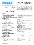
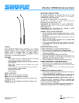
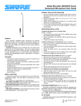
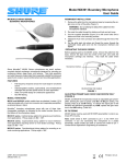
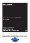
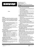
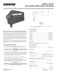
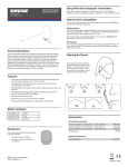
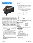
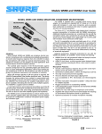
1
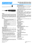
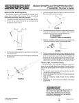
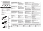
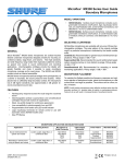
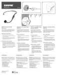
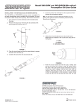
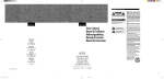
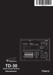
Model Microflex® MX200 Series
Overhead Microphones User Guide
GENERAL
Shure Microflex® MX200 Series microphones are miniature
electret condenser microphones designed for miking choirs and
performance groups. They are typically suspended over the heads
of the performers. Their high sensitivity and wide frequency range
make them suitable for recording, as well as sound reinforcement
applications. An attached 101 mm (4 in.) gooseneck allows them
to be easily aimed at the sound source.
FEATURES
• Wide dynamic range and frequency response for accurate sound
reproduction across the audio spectrum
• Interchangeable cartridges that provide an optimal polar pattern
choice for each application
• Supplied stand-mount adapter for portable applications (in-line
preamplifier versions only)
• White or black finish that blends unobtrusively with most
surroundings
• New RF filtering
VARIATIONS
All Microflex microphones are available with any one of three
interchangeable cartridges. The polar pattern of the cartridge is
indicated by the model number suffix:
C = Cardioid, S = Supercardioid, O= Omnidirectional
• MX202B/C, S, O: Black mini-condenser microphone; includes
cable, in-line preamplifier, and stand adapter.
• MX202W/C, S, O: White mini-condenser microphone; includes
cable, in-line preamplifier, and stand adapter.
• MX202BP/C, S, O: Black mini-condenser microphone; includes
cable and plate-mounted preamplifier.
Cardioid (C). Recommended for general sound reinforcement
applications. Pickup angle (-3 dB) = 130°.
Supercardioid (S). Recommended for sound reinforcement
applications requiring narrow or more distant coverage. Pickup
angle (-3 dB) = 115°.
Omnidirectional (O). Recommended for recording or remote
monitoring applications. Pickup angle = 360°.
GENERAL INSTALLATION GUIDELINES (Figure 1)
1. For choir installations, hang a microphone 0.6 to 0.9 m (2 to
3 ft.) in front of the first row, and 0.6 to 0.9 m (2 to 3 ft.) higher
than the heads of the singers in the last row. Aim the microphone at the back row.
2. When miking groups that move or vary in size, use a boom
stand and the supplied stand adapter.
3. If four or more microphones will be open at once, an automatic
mixer, such as the Shure SCM810 or FP410, is recommended. Set up the automatic mixer so that all overhead
microphones gate on simultaneously.
MICROPHONE APPLICATION AND SELECTION GUIDE
Application
Mounting Method
Preamplifier
Type
Color
Polar Pattern
Model
Cable length
Sound reinforcement for
choirs or theater
Stand-mounted or suspended
from ceiling
In Line
In Line
In Line
In Line
Plate Mounted
Plate Mounted
Plate Mounted
Plate Mounted
Black
White
Black
White
White
Black
White
Black
Cardioid
Cardioid
Supercardioid
Supercardioid
Cardioid
Supercardioid
Supercardioid
Cardioid
MX202B/C
MX202W/C
MX202B/S
MX202W/S
MX202WP/C
MX202BP/S
MX202WP/S
MX202BP/C
9 m (30 ft)
In Line
In Line
Black
White
Black
White
Omnidirectional
Omnidirectional
Omnidirectional
Omnidirectional
MX202B/N with R183B
MX202W/N with R183W
MX202BP/N with R183B
MX202BP/N with R183W
9 m (30 ft)
Suspended from ceiling
Ambience recording or
remote monitoring of speech
and vocals
Stand-mounted or suspended
from ceiling
MICROPHONE INSTALLATION (Figure 2)
The microphone is most stable when the gooseneck is bent into a
“lazy S” shape as shown in Figure 2. Use the supplied hanging clip
and heavy thread or monofilament fishing line to suspend the
microphone at a specific location.
©2006, Shure Incorporated
27J2836 (Rev. 1)
INSTALLING THE FOAM WINDSCREEN (Figure 3)
1. Press the foam windscreen onto the microphone until it snaps
into the groove located behind the cartridge.
2. To remove the windscreen, spread the gap in its mounting ring
with a screwdriver or thumbnail and pull the windscreen off.
Printed in U.S.A.
PREAMPLIFIER INSTALLATION
Equivalent Output Noise (A-weighted)
Cardioid: 28.0 dB SPL
Supercardioid: 26.5 dB SPL
Omnidirectional: 20.5 dB SPL
Signal to Noise Ratio (referenced at 94 dB SPL)
Cardioid: 66.0 dB
Supercardioid: 67.5 dB
Omnidirectional: 73.5 dB
Dynamic Range at 1 kΩ Load
96.2 dB
Plate-Mount Preamplifier Input Connections
1. Detach the preamplifier housing by removing the two Phillips
head screws from the back of the housing.
2. Remove the material from the hole in the center of the cover
plate or the center of the preamplifier housing.
3. Cut the cable to the desired hanging length, allowing for a 76
to 101 mm (3 to 4 in.) service loop.
4. Clamp the strain relief around the cable and insert the strain
relief into the hole.
5. Connect the cable leads to the terminal block (B = Black,
R = Red, S = Shield).
100 dB at 0 gain
Common Mode Rejection
45.0 dB minimum
Preamplifier Output Clipping Level (1% THD)
-6.0 dBV (0.5 V)
Plate-Mount Preamplifier Output Cable Connections
1. Using professional-quality, two-conductor, shielded microphone cable, thread the output cable from the outside of the
preamplifier through the hole with the black bushing.
2. Connect cable to pins as follows:
Pin 2 = +, Pin 3 = –, Shield = S.
3. Reattach the preamplifier housing.
-12 dBV at 0 gain
Polarity
Positive sound pressure on diaphragm produces positive voltage on pin 2 relative to pin 3 of output connector.
Power Requirements
11 to 52 Vdc phantom, 2.0 mA
Environmental Requirements
Operating Temperature Range: -18° C to 57° C
(0° F to 135° F)
Relative Humidity: 0 to 95%
Dimensions (Figure 6)
CEILING TILE INSTALLATION (Figure 4)
Remove: Plate-Mount Preamp Connection
1. Drill a 1/2” hole into the ceiling tile.
CAUTION: To avoid damaging the tile, use a 1/2" augur bit
and drill by hand or very slowly with a variable-speed drill.
2. Unplug the mini 4-pin connector from the preamp and feed the
cable through the hole.
3. Place the rubber grommet, tip down, over the cable and position it to suspend the microphone at the appropriate height.
4. Fit the grommet securely into the hole. For 5/8" ceiling tile, use
the supplied washer.
5. Reconnect the Preamp.
CERTIFICATION
Eligible to bear CE Marking. Conforms to European EMC Directive
89/336/EEC. Meets applicable tests and performance criteria in
European Standard EN55103 (1996) parts 1 and 2, for residential
(E1) and light industrial (E2) environments.
NOTE: For technical data by fax, phone 1-800-516-2525 and
follow the recorded instructions. For additional technical
assistance, phone Shure at (847) 600-2000. In Europe,
phone 49-7131-72140.
INSTALLING THE IN-LINE PREAMPLIFIER (Figure 4)
Use the two supplied mounting clamps to hold the preamplifier in
place on a wall or ceiling.
Shure, the Shure logo, and Microflex are registered trademarks
of Shure Incorporated.
ADJUSTING PREAMP GAIN: MX202B AND MX202W ONLY
(Figure 5)
MX202B and MX202W microphones include an adjustable gain
preamplifier, allowing the user to specify a 12 dB or 0 dB gain
setting. The preamp ships at 12 dB setting. To reduce the signal
gain at the MX202B and M202W preamplifier by 12dB, replace the
gain resistors to the 0dB setting (Table 5A).
FURNISHED ACCESSORIES
Snap-Fit Windscreen
Black (1 furnished, 4 in replacement kit) . . . . . . RK183WS
White (1). . . . . . . . . . . . . . . . . . . . . . . . . . . . . . . . 95B2064
Preamplifier Kit, Plate Mounted, White
(MX202BP & MX202WP) . . . . . . . . . . . . . . . . . . .RK202PK
Stand Adaptor (MX202B and MX202W) . . . . . . . . . 65B1752
RF FILTERING
MX200 Series must be used with RK100PK or RK202PK
preamplifier, in order to optimize RF immunity.
OPTIONAL ACCESSORIES
Desk Stand . . . . . . . . . . . . . . . . . . . . . . . . . . . . . . . . A202BB
SPECIFICATIONS
Frequency Response (Figure 7)
50 to 17,000 Hz
Polar Pattern (Figure 8)
Output Impedance
180 Ω actual (EIA rated at 150 Ω)
Sensitivity (At 1,000 Hz, open circuit voltage*)
Cardioid: -35.0 dBV/Pa (17.8 mV)
Supercardioid: -33.5 dBV/Pa (21.1 mV)
Omnidirectional: -27.5 dBV/Pa (42.2 mV)
REPLACEMENT PARTS
In-Line Preamplifier (Black). . . . . . . . . . . . . . . . . . .RK100PK
In-Line Preamplifier (White) . . . . . . . . . . . . . . . . RK100PKW
Omnidirectional Cartridge
(Black) . . . . . . . . . . R183B
(White) . . . . . . . . . R183W
Supercardioid Cartridge
(Black) . . . . . . . . . . R184B
(White) . . . . . . . . . R184W
Cardioid Cartridge
(Black) . . . . . . . . . . R185B
(White) . . . . . . . . . R185W
Strain Relief (MX202BP & MX202WP) . . . . . . . . . . . 80A479
Clamp (MX202B & MX202WP) . . . . . . . . . . . . . . . . . 80A476
Hang Clip . . . . . . . . . . . . . . . . . . . . . . . . . . . . . . . . . 80B489
All values -12 dB at 0 gain
*1 Pascal = 94 dB SPL
Maximum SPL (1 kHz at 1% THD, 1 kΩ load)
Cardioid: 124.2 dB
Supercardioid: 122.7 dB
Omnidirectional: 116.7 dB
All values +6 dB at 0 gain
2
MICROPHONE SUSPENDU MICROFLEX® SÉRIE MX200
GUIDE DE L'UTILISATEUR
• MX202B/C, S, O : Mini microphone électrostatique noir avec
câble, préampli et adaptateur de pied.
• MX202W/C, S, O : Mini microphone électrostatique blanc avec
câble, préampli et adaptateur de pied.
• MX202BP/C, S, O : Mini microphone électrostatique noir avec
câble et préampli monté sur plaque.
• MX202WP/C, S, O : Mini microphone électrostatique blanc avec
câble et préampli monté sur plaque.
Cardioïde (C). Recommandé pour les applications de sonorisation
générale. Angle de captage (-3 dB) = 130°.
Cardioïde (C). Recommandé pour les applications de sonorisation
générale. Angle de captage (-3 dB) = 130°.
Supercardioïde (S). Recommandé pour les applications de
sonorisation exigeant un captage plus étroit ou à plus grande
distance. Angle de captage (-3 dB) = 115°.
Omnidirectionnel (O). Recommandé pour l'enregistrement ou le
captage à distance. Angle de captage = 360°.
GÉNÉRALITÉS
Les Shure Microflex® série MX200 sont des microphones
électrostatiques conçus pour la prise de son de choeurs et groupes
vocaux. Ils sont en général suspendus au-dessus de la tête des
artistes. Leur haute sensibilité et large gamme de fréquence
permettent de les utiliser pour les enregistrements et la
sonorisation de scène. Un col de cygne intégré de 10 cm permet
de les orienter facilement vers la source sonore.
AVANTAGES
• Large gamme dynamique et courbe de réponse pour une
reproduction précise du son sur tout le spectre audio
• Capsules interchangeables permettant une courbe de directivité
optimale pour chaque application
• Adaptateur de pied inclus permettant l'utilisation sur un pied de
micro (versions à préampli en ligne seulement)
• Fini noir ou blanc assurant la discrétion dans la plupart des
décors
• Nouveau filtrage RF
DIRECTIVES GÉNÉRALES
POUR L'INSTALLATION (Figure 1)
1. Pour la prise de son des choeurs, suspendre un microphone à
60 à 90 cm au-dessus du premier rang et à 60 à 90 cm
au-dessus de la tête des choristes du dernier rang. Orienter le
microphone vers le dernier rang.
2. Pour la prise de son de groupes mobiles ou variables en nombre, utiliser une girafe et l'adaptateur de pied fourni.
3. Lorsque quatre microphones ou plus doivent être ouverts
simultanément l'usage d'une table de mélange automatique,
telle que la Shure SCM810 ou FP410 est recommandé.
Régler la table de mélange de façon à ce que tous les microphones suspendus soient activés simultanément.
VARIANTES
Tous les microphones Microflex sont fournis avec l'une des trois
capsules interchangeables. La courbe de directivité de la capsule
utilisée dans un micro particulier est indiquée par le suffixe du
numéro de modèle :
C = Cardioïde, S = Supercardioïde, O= Omnidirectionnelle
GUIDE DE SÉLECTION ET D'APPLICATION DES MICROPHONES
Application
Méthode de montage
Micros à préampli
Couleur
Courbe de directivité
Modèle
Longueur du
câble
Sonorisation de
choeurs ou de
théâtre
Sur pied ou suspendu
au plafond
En ligne
En ligne
En ligne
En ligne
Monté sur plaque
Monté sur plaque
Monté sur plaque
Monté sur plaque
Noir
Blanc
Noir
Blanc
Blanc
Noir
Blanc
Noir
Cardioïde
Cardioïde
Supercardioïde
Supercardioïde
Cardioïde
Supercardioïde
Supercardioïde
Cardioïde
MX202B/C
MX202W/C
MX202B/S
MX202W/S
MX202WP/C
MX202BP/S
MX202WP/S
MX202BP/C
9m
En ligne
En ligne
Noir
Blanc
Noir
Blanc
Omnidirectionnelle
Omnidirectionnelle
Omnidirectionnelle
Omnidirectionnelle
MX202B/N avec R183B
MX202W/N avec R183W
MX202BP/N avec R183B
MX202BP/N avec R183W
9m
Suspendu au plafond
Enregistrement Sur pied ou suspendu
d'ambiance ou
au plafond
contrôle à
distance de la
voix
INSTALLATION DU COUPE-VENT EN MOUSSE (Figure 3)
1. Enfoncer le coupe-vent en mousse sur le microphone jusqu'à
ce qu'il s'encliquette dans la gorge se trouvant derrière la
capsule.
2. Pour le retirer, écarter les extrémités de la bague de montage
avec un tournevis ou une punaise et le dégager du micro.
INSTALLATION DU MICROPHONE (Figure 2)
La meilleure stabilité du micro est obtenue avec le col de cygne
courbé en forme de "S" allongé, comme illustré à la figure 2.
Suspendre le microphone à l'endroit désiré au moyen du clip fourni
et d'un cordon ou d'un fil de pêche monofilament solide.
3
INSTALLATION DU PRÉAMPLI
NPA maximum (1 kHz avec DHT de 1 %, charge de 1 KΩ)
Cardioïde : 124,2 dB
Supercardioïde : 122,7 dB
Omnidirectionnel : 116,7 dB
Branchement d'entrée du préampli monté sur plaque
1. Retirer les deux vis Phillips au dos du boîtier du préampli pour
le détacher.
2. Ouvrir le trou pré-perforé du centre du couvercle ou du boîtier
du préampli.
3. Couper le câble à la longueur voulue en prévoyant 8 à 10 cm
supplémentaire pour former une boucle.
4. Refermer le soulagement de traction sur le câble et l'insérer
dans le trou.
5. Brancher les fils du câble sur le bornier (B = noir, R = rouge, S
= Blindage).
Branchement du câble de sortie du préampli monté sur
plaque
1. Utiliser un câble de microphone blindé à deux conducteurs, de
qualité professionnelle. Insérer le câble de l'extérieur du
préampli, dans le trou muni d'une bague noire.
2. Brancher le câble comme suit : Broche 2 = +, Broche 3 = –,
Blindage = S.
3. Remonter le boîtier du préampli.
+6 dB à 0 gain
Bruit de sortie équivalent (pondération en A)
Cardioïde : 28,0 dB NPA
Supercardioïde : 26,5 dB NPA
Omnidirectionnel : 20,5 dB NPA
Rapport signal/bruit (mesuré avec une pression acoustique
de 94 dB)
Cardioïde : 66,0 dB
Supercardioïde : 67,5 dB
Omnidirectionnel : 73,5 dB
Gamme dynamique avec charge de 1 kΩ
96,2 dB
100,0 dB à 0 gain
Rejet en mode commun
45,0 dB au minimum
Niveau d'écrêtage de sortie préampli (1 % DHT)
-6,0 dBV (0,5 V)
-12,0 dBV à 0 gain
Polarité
Une pression acoustique positive sur le diaphragme produit une
tension positive sur la broche 2 par rapport à la broche 3 du connecteur de sortie.
Alimentation
11 à 52 V c.c. duplex, 2,0 mA
Environnement
Plage de températures de fonctionnement : -18 à 57°C
Humidité relative : 0 à 95%
Dimensions (Figure 6)
INSTALLATION SUR CARREAU DE PLAFOND :
Enlever : Branchement du préampli monté sur plaque (Figure 4)
1. Percer un trou de ½ po dans le carreau de plafond.
ATTENTION : Pour éviter d'endommager le carreau, utiliser
une mèche hélicoïdale de ½ po et percer à la main ou très
lentement avec une perceuse à vitesse variable.
2. Débrancher le connecteur miniature à 4 broches du préampli
et faire passer le câble par le trou.
3. Placer l'oeillet en caoutchouc, embout vers le bas, sur le câble
et le placer de façon à pouvoir suspendre le microphone à la
hauteur appropriée.
4. Bien ajuster l'œillet dans le trou. Pour un carreau de plafond
de 5/8 po, utiliser la rondelle fournie.
5. Rebrancher le préampli.
HOMOLOGATION
Autorisé à porter la marque CE. Conforme à la directive CEM
européenne 89/336/CEE. Conforme aux critères applicables de
test et de performances de la norme européenne EN 55103 (1996)
parties 1 et 2 pour les environnements résidentiels (E1) et
d'industrie légère (E2).
REMARQUE : Pour toute information technique par télécopie,
composer le 1-800-516-2525 et suivre les instructions de
l'enregistrement.
Pour
toute
assistance
technique
supplémentaire, appeler Shure au (847) 600-2000. En Europe,
appeler le 49-7131-72140.
INSTALLATION DU PRÉAMPLI EN LIGNE (Figure 4)
Fixer le microphone sur un mur ou un plafond à l'aide des deux
pinces de montage fournies.
RÉGLAGE DU GAIN DU PRÉAMPLI : MX202B ET
MX202W SEULEMENT (Figure 5)
Les microphones MX202B et MX202W comprennent un
préamplificateur à gain réglable, ce qui permet à l'utilisateur de
choisir un réglage du gain de 12 dB ou de 0 dB. Pour réduire le
gain aux préamplis MX202B et MX202W de 12 dB, remettre les
résistances de gain au réglage 0 dB, (Tableau 5A).
ACCESSOIRES FOURNIS
Kit de préampli, monte sur plaque, blanche
(MX202BP et MX202WP) . . . . . . . . . . . . . . . . . .RK202PK
Coupe-vent encliquetable (1 fourni)
4 dans le kit de pièces de rechange, noir. . . . . . RK183WS
Blanc (1). . . . . . . . . . . . . . . . . . . . . . . . . . . . . . . . 95B2064
Adaptateur de pied (MX202B et MX202W). . . . . . . 65B1752
FILTRAGE RF :
La série MX200 doit être utilisée avec le préampli RK100PK ou un
RK202PK de manière à optimiser l'immunité RF.
CARACTÉRISTIQUES
ACCESSOIRES EN OPTION
Socle de pupitre . . . . . . . . . . . . . . . . . . . . . . . . . . . . A202BB
Courbe de réponse (Figure 7)
50 à 17 000 Hz
Courbe de directivité (Figure 8)
Impédance de sortie
180 Ω réels (EIA nominale 150 Ω)
Sensibilité en circuit ouvert
(à 1000 Hz réf. 1V/Pascal*)
Cardioïde : -35,0 dBV/Pa (17,8 mV)
Supercardioïde : -33,5 dBV/Pa (21,1 mV)
Omnidirectionnel : -27,5 dBV/Pa (42,2 mV)
PIÈCES DE RECHANGE
Capsule omnidirectionnelle
Capsule Supercardioïde
Capsule cardioïde
(noire) . . . . . . . . . . R183B
(blanche) . . . . . . . R183W
(noire) . . . . . . . . . . R184B
(blanche) . . . . . . . R184W
(noire) . . . . . . . . . . R185B
(blanche) . . . . . . . R185W
Soulagement de traction
(MX202BP et MX202WP) . . . . . . . . . . . . . . . . . . . 80A479
Attache (MX202B et MX202W) . . . . . . . . . . . . . . . . . 80A476
Pince de suspension . . . . . . . . . . . . . . . . . . . . . . . . . 80B489
Préampli en ligne (noire) . . . . . . . . . . . . . . . . . . . . .RK100PK
Préampli en ligne (blanc) . . . . . . . . . . . . . . . . . . RK100PKW
-12 dB à 0 gain
*1 Pascal = 94 dB NPA
4
GEBRAUCHSANLEITUNG FÜR MICROFLEX® OVERHEADMIKROFONE DER REIHE MX200
• MX202B/C, S, O: Schwarzes Mini-Kondensatormikrofon,
einschließlich Kabel, In-line-Vorverstärker und Stativadapter.
• MX202W/C, S, O: Weißes Mini-Kondensatormikrofon,
einschließlich Kabel, In-line-Vorverstärker und Stativadapter.
• MX202BP/C, S, O: Schwarzes Mini-Kondensatormikrofon,
einschließlich Kabel und Vorverstärker zum Wandeinbau.
• MX202WP/C, S, O: Weißes Mini-Kondensatormikrofon,
einschließlich Kabel und Vorverstärker zum Wandeinbau.
Niere (C). Für allgemeine Mikrofonanwendungen empfohlen.
Ansprechwinkel (-3 dB) = 130°.
Superniere (S). Für Mikrofonanwendungen empfohlen, die eine
engere oder weiter entfernte Signal-Abdeckung, die eine engere
oder weiter entfernte Abdeckung erfordern. Ansprechwinkel (-3
dB) = 115°.
Kugel (O). Für Aufzeichnungs- oder
Fernüberwachungsanwendungen empfohlen. Ansprechwinkel =
360°.
ALLGEMEINES
Shure Microflex® Mikrofone der Reihe MX200 sind Mini-Elektretkondensatormikrofone, die zur Aufnahme von Chören und
aufführenden Gruppen vorgesehen sind. Üblicherweise hängen
sie über den Köpfen der Aufführenden herab. Durch ihre hohe
Empfindlichkeit und den breiten Frequenzbereich eignen sie sich
zu Aufzeichnungszwecken sowie für Beschallungsanwendungen.
Ein daran befestigter 10 cm langer Schwanenhals ermöglicht ihre
einfache Ausrichtung auf die Schallquelle.
MERKMALE
• Hoher Dynamikbereich und breiter Frequenzgang für genaue
Tonwiedergabe über das gesamte Tonfrequenzspektrum hinweg
• Austauschbare Kapseln, die eine optimale Richtcharakteristik für
jeden Verwendungszweck ermöglichen
• Mitgelieferter Adapter zur Stativbefestigung für tragbare
Anwendungen (nur bei In-line-Vorverstärkerausführungen)
• Weiße oder schwarze Ausführung, die sich unauffällig in die
meisten Umgebungen einfügt
• Neues Design zur HF Filterung
ALLGEMEINE INSTALLATIONSRICHTLINIEN (Abbildung 1)
1. Für Choraufnahmen ein Mikrofon knapp einen Meter vor der
ersten Reihe und knapp 1 Meter höher als die Köpfe der
Sänger in der letzten Reihe aufhängen. Das Mikrofon auf die
hintere Reihe ausrichten.
2. Bei Aufnahme von Gruppen, die sich bewegen oder veränderlich groß sind, einen Mikrofonständer und den mitgelieferten
Adapter verwenden.
3. Wenn vier oder mehr Mikrofone gleichzeitig verwendet werden sollen, ist der Einsatz eines Automatikmischers, wie z.B.
Shure SCM810 oder FP410, zu empfehlen. Den Automatikmischer so einstellen, daß alle Overhead-Mikrofone gleichzeitig öffnen.
VARIANTEN
Alle Microflex-Mikrofone sind mit einer von drei austauschbaren
Kapseln lieferbar. Die Richtcharaktersitik der Kapsel wird durch
das Kürzel am Ende der Modellnummer angegeben.
C = Niere, S = Superniere, O= Kugel
ANLEITUNG ZUR MIKROFONVERWENDUNG UND -AUSWAHL
Verwendungszweck
Installationsverfahren
Vorverstärkertyp
Farbe
Polarmuster
Modell
Kabellänge
Tonverstärkung für Chor
oder Theater
Auf einem Stativ montiert
oder von der Decke hängend
In-line
In-line
In-line
In-line
Plattenmontiert
Plattenmontiert
Plattenmontiert
Plattenmontiert
Schwarz
Weiß
Schwarz
Weiß
Weiß
Schwarz
Weiß
Schwarz
Kardioid
Kardioid
Superkardioid
Superkardioid
Kardioid
Superkardioid
Superkardioid
Kardioid
MX202B/C
MX202W/C
MX202B/S
MX202W/S
MX202WP/C
MX202BP/S
MX202WP/S
MX202BP/C
9m
In-line
In-line
Schwarz
Weiß
Schwarz
Weiß
Alle Richtungen
Alle Richtungen
Alle Richtungen
Alle Richtungen
MX202B/N mit R183B
MX202W/N mit R183W
MX202BP/N mit R183B
MX202BP/N mit R183W
9m
Von der Decke hängend
Umgebungsaufzeichnung
Auf einem Stativ montiert
oder Fernüberwachung oder von der Decke hängend
von Sprache und Gesang
Von der Decke hängend
INSTALLATION DES VORVERSTÄRKERS
Installation des Mikrofons (Abbildung 2)
Das Mikrofon ist am stabilsten, wenn der Schwanenhals in die
Form eines “langgezogenen S” gebogen wird, wie in Abbildung 2
dargestellt. Das Mikrofon mit Hilfe der mitgelieferten
Hängeklammer und mit starkem Faden oder einer Angelschnur an
einer bestimmten Stelle aufhängen.
EINGANGSANSCHLÜSSE DES VORVERSTÄRKERS ZUM
WANDEINBAU
1. Das Vorverstärkergehäuse abnehmen, indem die beiden
Kreuzschlitz-Kopfschrauben aus der Rückseite des Gehäuses
herausgeschraubt werden.
2. Das Material aus der Öffnung in der Mitte der Abdeckplatte
oder aus der Mitte des Vorverstärkergehäuses entfernen.
3. Das Kabel auf die gewünschte Länge zuschneiden und dabei
eine 8-10 cm lange Reserve berücksichtigen.
4. Die Zugentlastung um das Kabel klemmen und in die Öffnung
einführen.
5. Die Kabelleitungen an die Klemmleiste anschließen
(B = Schwarz, R = Rot, S = Abschirmung).
ANBRINGUNG DES SCHAUMSTOFF-WINDSCHUTZES
(Abbildung 3)
1. Den Schaumstoff-Windschutz auf das Mikrofon drücken, bis
er in die Rille hinter der Kapsel einrastet.
2. Zum Abnehmen des Windschutzes den Spalt in seinem
Befestigungsring mit einem Schraubenzieher oder Daumennagel auseinander spreizen und den Windschutz abziehen.
5
Rauschabstand (bezogen auf 94 dB Schalldruckpegel)
Niere: 66,0 dB
Superniere: 67,5 dB
Kugel: 73,5 dB
Dynamikbereich bei 1 kΩ Belastung
96,2 dB
AUSGANGSKABELANSCHLÜSSE DES VORVERSTÄRKERS
ZUM WANDEINBAU
1. Hochwertiges, zweipoliges, abgeschirmtes Mikrofonkabel verwenden und das Ausgangskabel von der Außenseite des Vorverstärkers durch die Öffnung mit der schwarzen Hülse
führen.
2. Das Kabel wie folgt mit den Pins verbinden: Pin 2 = +, Pin
3 = –, Abschirmung = S
3. Das Vorverstärkergehäuse wieder anbringen.
100,0 dB bei 0 dB Verstärkungsfaktor
Gleichtaktunterdrückung
mindestens 45,0 dB
Maximaler Ausgangspegel des Vorverstärkers
(1% Klirrfaktor)
-6,0 dBV (0,5 V)
MONTAGE AN DECKENPLATTEN (Abbildung 4):
1. Ein Loch mit ½ Zoll (13 mm) Durchmesser in die Deckenplatte
bohren.
VORSICHT: Einen ½-Zoll (13 mm)-Bohrer verwenden und von
Hand oder sehr langsam mit einer Bohrmaschine mit stufenloser
Drehzahl bohren, damit die Platte nicht beschädigt wird.
2. Den 4-Pin-Ministecker aus dem Vorverstärker ziehen und das
Kabel durch das Loch führen.
3. Die Gummitülle mit der Spitze nach unten auf das Kabel setzen und so positionieren, dass das Mikrofon in der richtigen
Höhe aufgehängt ist.
4. Die Tülle fest in das Loch einpassen. Bei Deckenplatten mit
einer Stärke von 5/8 Zoll (16 mm) die mitgelieferte Unterlegscheibe verwenden.
5. Den Vorverstärker wieder anschließen.
-12,0 dBV bei 0 dB Verstärkungsfaktor
Polarität
Positiver Schalldruck an der Membran erzeugt positive
Spannung an an Pin 2 in bezug auf Pin 3 des
Ausgangssteckers.
Leistungsbedarf
11 bis 52 V Phantom-Spannung, 2,0 mA
Umgebungsbedingungen
Betriebstemperaturbereich: -18 bis 57°C
Relative Feuchtigkeit: 0 to 95 %
Abmessungen (Abbildung 6)
ZERTIFIZIERUNG
Zur CE-Kennzeichnung berechtigt. Entspricht der EU-Richtlinie
über elektromagnetische Verträglichkeit 89/336/EEC. Erfüllt die
Prüfungs- und Leistungskriterien der europäischen Norm EN
55103 (1996) Teil 1 und 2 für Wohngebiete (E1) und
Leichtindustriegebiete (E2).
INSTALLATION DES IN-LINE-VORVERSTÄRKERS
(Abbildung 4)
Den Vorverstärker mit Hilfe der beiden mitgelieferten
Montageschellen an einer Wand oder Decke befestigen.
HINWEIS: Faxabruf technischer Daten unter der Rufnummer
1–800–516–2525 (nur innerhalb der USA), dabei
Anleitungen des Anrufbeantworters befolgen. Weitere
technische Unterstützung wird von Shure unter der
Rufnummer +1 (847) 600–2000 geleistet. In Europa bitte +49
(7131) 72140 anrufen.
EINSTELLUNG DES VERSTÄRKUNGSFAKTORS AM
VORVERSTÄRKER: NUR MX202B UND MX202W
(ABBILDUNG 5)
MX202B und MX202W Mikrofone enthalten einen Vorverstärker
mit Verstärkungseinstellung, der dem Benutzer ermöglicht, eine
12-dB- oder 0-dB-Verstärkungseinstellung zu wählen. Um die
Signalverstärkung am Vorverstärker MX202B und MX202W um 12
dB zu verringern, die Widerstandsbauteile auf die 0 dB
Verstärkung ändern (entsprechend Tabelle 5A).
HF-FILTERUNG:
Zur Optimierung der HF-Störfestigkeit muss die die Modellreihe
MX200 mit dem Vorverstärker RK100PK oder RK202PK
verwendet werden.
MITGELIFERTES ZUBEHÖR
Ersatzvorverstärker zum Wandeinbau, weiß
(MX202BP und MX202WP) . . . . . . . . . . . . . . . . .RK202PK
Einrastender Schaumstoff-Windschutz
Schwarz (1 x mitgeliefert, 4 x in Ersatzpackung) . RK183WS
Weiß (1) . . . . . . . . . . . . . . . . . . . . . . . . . . . . . . . . 95B2064
Stativadapter (MX202B und MX202W) . . . . . . . . . . 65B1752
TECHNISCHE DATEN
Frequenzgang (Abbildung 7)
50 bis 17.000 Hz
Richtcharaktersitik (Abbildung 8)
Ausgangsimpedanz
Ist-Wert: 180 Ω (EIA-Nennwert: 150 Ω)
Leerlaufempfindlichkeit (bei 1 kHz, bezogen auf
1 V/Pascal*)
Niere: -35,0 dBV/Pa (17,8 mV)
Superniere: -33,5 dBV/Pa (21,1 mV)
Kugel: -27,5 dBV/Pa (42,2 mV)
SONDERZUBEHÖR
Tischstativ . . . . . . . . . . . . . . . . . . . . . . . . . . . . . . . . . A202BB
ERSATZTEILE
Kugelkapsel
(Schwarz). . . . . . . . R183B
(Weiß) . . . . . . . . . R183W
Supernierenkapsel
Schwarz) . . . . . . . . R184B
(Weiß) . . . . . . . . . R184W
Nierenkapsel
(Schwarz). . . . . . . . R185B
(Weiß) . . . . . . . . . R185W
Zugentlastung (MX202BP und MX202WP). . . . . . . . 87A479
Klemme (MX202B und MX202W) . . . . . . . . . . . . . . . 80A476
Hängeklammer . . . . . . . . . . . . . . . . . . . . . . . . . . . . . 80B489
In-Line-Vorverstärker (Schwarz) . . . . . . . . . . . . . . .RK100PK
In-Line-Vorverstärker (Weiß). . . . . . . . . . . . . . . . RK100PKW
-12 dB bei to 0 dB Verstärkungsfaktor
*1 Pascal = 94 dB Schalldruckpegel
Maximaler Schalldruckpegel (1 kHz bei 1 % Klirrfaktor, 1 kΩ
Last)
Niere: 124,2 dB
Superniere: 122,7 dB
Kugel: 116,7 dB
+6 dB bei 0 dB Verstärkungsfaktor
Äquivalentes Ausgangsrauschen (mit A-Gewichtung)
Niere: 28,0 dB Schalldruckpegel
Superniere: 26.5 dB Schalldruckpegel
Kugel: 20,5 dB Schalldruckpegel
6
GUIA DEL USUARIO DEL MICROFONO SUSPENDIDO
MICROFLEX® SERIE MX200
• MX202B/C, S, O: Micrófono de condensador en miniatura negro;
incluye cable, preamplificador en línea y adaptador de pedestal.
• MX202W/C, S, O: Micrófono de condensador en miniatura
blanco; incluye cable, preamplificador en línea y adaptador de
pedestal.
• MX202BP/C, S, O: Micrófono de condensador en miniatura
negro; incluye cable y preamplificador montado en placa.
• MX202WP/C, S, O: Micrófono de condensador en miniatura
blanco; incluye cable y preamplificador montado en placa.
Cardioide (C). Se recomienda para aplicaciones generales de
refuerzo de sonido. Angulo de captación (nivel de -3 dB) = 130°.
Supercardioide (S). Se recomienda para aplicaciones de
refuerzo de sonido en las cuales la zona de cobertura es más
estrecha o se requiere un alcance mayor. Angulo de captación
(nivel de -3 dB) = 115°.
Omnidireccional (O). Se recomienda para aplicaciones de
grabación y de monitoreo remoto de sonido. Angulo de captación
= 360°.
GENERALIDADES
Los micrófonos Shure Microflex® serie MX200 son micrófonos de
condensador de electreto en miniatura diseñados para la
captación de coros y grupos musicales. Típicamente se
suspenden por encima de las cabezas de los ejecutores. Su alta
sensibilidad y amplia gama de frecuencias los hacen útiles para
situaciones de grabación o de refuerzo de sonido. Un cuello de
cisne de 10 cm (4 pulg) permite orientarlos fácilmente hacia la
fuente sonora.
CARACTERISTICAS
• Gama dinámica y respuesta de frecuencia amplias para una
reproducción precisa del sonido en todo el espectro audible
• Cartuchos intercambiables que permiten elegir el patrón polar
óptimo para cada aplicación
• Adaptador para pedestal para uso con equipos portátiles (sólo
modelos con preamplificador en línea)
• Acabado en blanco o en negro que se combina discretamente
con el entorno
• Nuevo sistema de filtro de radiofrecuencia
GUIA GENERAL DE INSTALACION (Figura 1)
1. Para captar las voces de un coro, suspenda un micrófono 0,61 m delante de la primera fila de cantantes y 0,6-1 m por
encima de las cabezas de la última fila de cantantes. Oriente
el micrófono hacia la última fila.
2. Para captar grupos que se moverán o que variarán de
tamaño, utilice un soporte tipo jirafa y el adaptador de pedestal incluido.
3. Si cuatro o más micrófonos estarán activos simultáneamente,
se recomienda usar una consola mezcladora automática tal
como la SCM810 ó la FP410 de Shure. Configure la consola
mezcladora automática de manera que todos los micrófonos
suspendidos se activen simultáneament
VARIACIONES
Todos los micrófonos Microflex se ofrecen con uno de tres
cartuchos intercambiables. El patrón polar de captación del
cartucho se designa por el sufijo que tiene en su número de
modelo:
C = Cardioide, S = Supercardioide, O = Omnidireccional
GUIA PARA LA SELECCION Y USO DE MICROFONOS
Uso
Método de montaje
Tipo de
preamplificador
Color
Patrón polar
Modelo
Largo de cable
Refuerzo de sonido para
coros o presentaciones
teatrales
Montados en jirafas o
suspendidos del techo
En línea
En línea
En línea
En línea
Montado en Placa
Montado en Placa
Montado en Placa
Montado en Placa
Negro
Blanco
Negro
Blanco
Blanco
Negro
Blanco
Negro
Cardioide
Cardioide
Supercardioide
Supercardioide
Cardioide
Supercardioide
Supercardioide
Cardioide
MX202B/C
MX202W/C
MX202B/S
MX202W/S
MX202WP/C
MX202BP/S
MX202WP/S
MX202BP/C
9 m (30 pies)
En línea
En línea
Negro
Blanco
Negro
Blanco
Omnidireccional MX202B/N con R183B
Omnidireccional MX202W/N con R183W
Omnidireccional MX202BP/N con R183B
Omnidireccional MX202BP/N con R183W
Grabación de sonido
ambiental o monitoreo
remoto de voces
Suspendidos del techo
Montados en jirafas o
suspendidos del techo
INSTALACION DEL MICROFONO (Figura 2)
El micrófono queda más estable cuando el cuello de cisne se
dobla en forma de una “S” suave, como se muestra en la Figura 3.
Utilice la presilla de colgado incluida y un hilo grueso o hilo de
pescar de monofilamento para suspender el micrófono en el punto
deseado.
9 m (30 pies)
CONEXIÓN DEL PREAMPLIFICADOR
Conexión del cable de entrada del preamplificador de
montaje en placa
1. Suelte la caja del preamplificador sacando los dos tornillos
Phillips de su parte trasera.
2. Quite el material del agujero en el centro de la cubierta o en el
centro de la caja del preamplificador.
3. Corte el cable al largo deseado, dejando un largo adicional de
8-10 cm para mantenimiento.
4. Instale el amortiguador de esfuerzos en el cable e insértelo en
el agujero.
5. Conecte los conductores del cable al bloque de bornes (B =
Negro, R = Rojo, S = Blindaje).
INSTALACION DE LA PANTALLA DE ESPUMA (Figura 3)
1. Deslice la pantalla de espuma sobre el micrófono hasta que
se enganche en la ranura ubicada detrás del cartucho del
mismo.
2. Para quitar la pantalla, abra la separación de su anillo de montaje con un destornillador o la uña y tírela hasta quitarla.
7
Gama dinámica con carga de 1 kΩ
96,2 dB
Conexión del cable de salida del preamplificador de
montaje en placa
1. Utilice cable para micrófonos de calidad profesional, de dos
conductores con blindaje, y pase el cable de salida desde el
exterior del preamplificador a través del agujero con el buje
negro.
2. Conecte el cable a las clavijas de la manera siguiente: Clavija
2 = (+); Clavija 3 = (-); Blindaje = S.
3. Vuelva a instalar la caja del preamplificador.
100,0 dB con ganancia en 0
Rechazo en modo común
45,0 dB mínimo
Nivel de limitación de salida del preamplificador (1% THD)
-6,0 dBV (0,5 V)
-12,0 dBV con ganancia en 0
Polaridad
Una presión positiva en el diafragma del micrófono produce un
voltaje positivo en la clavija 2 con respecto a la clavija 3 del
conector de salida.
Requisitos de alimentación
11 a 52 VCC de potencia fantasma nominal; 2,0 mA
Requisitos de entorno
Gama de temperatura de funcionamiento: -18° a 57°C (0° a
135°F)
Humedad relativa: 0 a 95%
Dimensiones (Figura 6)
INSTALACIÓN EN CIELORRASO: (Figura 4)
1. Perfore un agujero de 1/2 pulg en la losa del cielorraso.
PRECAUCION: Para evitar dañar la losa, use una broca tipo
sinfín de 1/2 pulg y perfore de forma manual o muy lentamente con un taladro de velocidad variable.
2. Desenchufe el conector miniatura de 4 clavijas del preamplificador y pase el cable por el agujero.
3. Coloque el ojal de caucho, con la punta hacia abajo, sobre el
cable y ubíquelo de manera que sostenga el micrófono en la
altura correcta.
4. Encaje el ojal de caucho firmemente en el agujero. Para una
losa de 5/8 pulg, use la arandela suministrada
5. Vuelva a conectar el preamplificador
INSTALACION DEL PREAMPLIFICADOR EN LINEA (Figura 4)
Utilice las dos abrazaderas de montaje incluidas para fijar el
preamplificador a una pared o al techo.
CERTIFICACIONES
Califica para llevar las marcas CE. Cumple la directiva europea 89/
336/EEC de compatibilidad electromagnética. Se ajusta a los
criterios correspondientes de verificación y funcionamiento
establecidos en la norma europea EN 55103 (1996), partes 1 y 2,
para zonas residenciales (E1) y zonas de industria ligera (E2).
NOTA: Para obtener información técnica vía Fax, llame al
1-800-516-2525 y siga las instrucciones dadas en la grabación.
Para recibir soporte técnico adicional, llame a Shure al teléfono
(847) 600-2000. En Europa, llame al 49-7131-72140.
AJUSTE DE LA GANANCIA DEL PREAMPLIFICADOR:
MX202B Y MX202W SOLAMENTE (Figura 5)
Los micrófonos MX202B y MX202W incluyen un preamplificador
con ganancia ajustable que permite al usuario especificar una
ganancia de 12 ó 0 dB. Para reducir la ganancia de la señal en el
preamplificador MX202B y MX202W en 12 dB, ponga las
resistencias de ganancia en la posición de 0 dB, (Tabla 5A).
ACCESSORIOS SUMNISTRADOS
Juego de preamplificador, montado en placa,
blanco (MX202BP y MX202WP) . . . . . . . . . . . . .RK202PK
Pantallas con anillo elástico
Negro, (1 suministrado, 4 en juego de repuestos) RK183WS
Blanco (1). . . . . . . . . . . . . . . . . . . . . . . . . . . . . . . 95B2064
Adaptador de pedestal (MX202B y MX202W) . . . . 65B1752
FILTRADO DE RF:
La serie MX200 se debe utilizar con el preamplificador RK100PK
o un RK202PK para poder optimizar la inmunidad a la
radiofrecuencia.
ACCESSORIOS OPCIONALES
Pedestal de escritorio . . . . . . . . . . . . . . . . . . . . . . . . A202BB
ESPECIFICACIONES
Respuesta de frecuencia (Figura 7)
50 a 17.000 Hz
Patrón polar (Figura 8)
Impedancia de salida
Real: 180 Ω (nominal según EIA: 150 Ω)
Sensibilidad en circuito abierto (a 1 kHz con ref. a
1 V/Pascal*)
Cardioide: -35,0 dBV/Pa (17,8 mV)
Supercardioide: -33,5 dBV/Pa (21,1 mV)
Omnidireccional: -27,5 dBV/Pa (42.2 mV)
REPUESTOS
Cartucho omnidireccional
Cartucho de supercardioide
Cartucho de cardioide
(negro) . . . . . . . . . . R183B
(blanco) . . . . . . . . R183W
(negro) . . . . . . . . . . R184B
(blanco) . . . . . . . . R184W
(negro) . . . . . . . . . . R185B
(blanco) . . . . . . . . R185W
Amortiguador de esfuerzos
(MX202BP y MX202WP) . . . . . . . . . . . . . . . . . . . 801A479
Pinza (MX202B y MX202W) . . . . . . . . . . . . . . . . . . . 80A476
Presilla para colgar . . . . . . . . . . . . . . . . . . . . . . . . . . 80B489
Preamplificador en línea (negro) . . . . . . . . . . . . . .RK100PK
Preamplificador en línea (blanco) . . . . . . . . . . . . RK100PKW
-12 dB con ganancia en 0
*1 Pascal = 94 dB SPL
Intensidad máx. sonido (1 kHz con 1% THD, carga de 1 kΩ)
Cardioide: 124,2 dB
Supercardioide: 122,7 dB
Omnidireccional:116,7 dB
Ruido equivalente de salida (ponderación A)
Cardioide: 28,0 dB SPL
Supercardioide: 26,5 dB SPL
Omnidireccional: 20,5 dB SPL
+6 dB con ganancia en 0
Relación de señal a ruido (con presión acústica de referencia
de 94 dB)
Cardioide: 66,0 dB
Supercardioide: 67,5 dB
Omnidireccional: 73,5 dB
8
GUIDA D'USO DEI MICROFONI PENSILI MICROFLEX®
SERIE MX200
C = Cardioide, S = Supercardioide, O= Omnidirezionale
• MX202B/C, S, O: microfono nero tipo miniatura a condensatore;
include cavo, preamplificatore in linea e adattatore per supporto
• MX202W/C, S, O: microfono bianco tipo miniatura a
condensatore; include cavo, preamplificatore in linea e
adattatore per supporto
Cardioide (C). Raccomandato per impianti di amplificazione
sonora di tipo generale. Angolo di ricezione (-3 dB) = 130°.
Supercardioide (S). Raccomandato per impianti di amplificazione
sonora che richiedono una direttività o portata maggiore. Angolo di
ricezione (-3 dB) = 115°.
Omnidirezionale (O). Raccomandato per impianti di registrazione
o monitoraggio a distanza. Angolo di ricezione = 360°.
DESCRIZIONE GENERALE
I microfoni Shure Microflex® serie MX200 sono microfoni tipo
miniatura a condensatore con elettrete concepiti per l'uso da parte
di cori e gruppi artistici. In genere vanno sospesi sopra la testa
degli artisti. L'elevata sensibilità e la vasta gamma di frequenze li
rendono adatti sia agli impianti di registrazione che a quelli di
amplificazione sonora. Un collo d'oca di 10 cm, collegato, permette
di rivolgerli facilmente verso la sorgente sonora.
CARATTERISTICHE
• Gamma dinamica di elevato valore e risposta in frequenza a
larga banda, ai fini di una riproduzione precisa del suono in tutto
il campo di frequenze audio
• Cartucce intercambiabili che consentono di effettuare una scelta
ottimale del diagramma polare di ricezione per ogni applicazione
• Adattatore per montaggio su supporto, in dotazione, per sistemi
portatili (solo versioni con preamplificatore in linea)
• Finitura bianca o nera che armonizza con la maggior parte delle
superfici circostanti
• Nuovo filtro RF
LINEE GUIDA GENERALI DI INSTALLAZIONE (Figura 1)
1. Per i cori, sospendere il microfono a una distanza orizzontale
compresa tra 60 cm e 1 m rispetto alla prima fila e a una distanza verticale compresa tra 60 cm e 1 m rispetto alla testa dei
cantanti dell'ultima fila. Rivolgere il microfono verso l'ultima
fila.
2. Quando si usa il microfono con gruppi che si spostano o variano di numero, adoperare una giraffa e l'adattatore per supporto, in dotazione.
3. Se quattro o più microfoni saranno in funzione contemporaneamente, si raccomanda l'uso di un mixer automatico,
come il modello Shure SCM810 o FP410. Regolare il mixer
automatico in modo che attivi simultaneamente tutti i microfoni sospesi.
DESCRIZIONE DEI MODELLI
Tutti i microfoni Microflex sono dotati di una cartuccia a scelta fra
tre modelli intercambiabili. Il diagramma polare della cartuccia è
indicato dal suffisso del numero di modello:
GUIDA ALLA SELEZIONE DEL MICROFONO
Scopo
Metodo di montaggio
Tipo di
preamplificatore
Colore
Diagramma
polare
Modello
Lunghezza
del cavo
Amplificazione sonora
della voce di cori o attori
Su supporto o sospeso
dal soffitto
Nero
Bianco
Nero
Bianco
Bianco
Nero
Bianco
Nero
Cardioide
Cardioide
Supercardioide
Supercardioide
Cardioide
Supercardioide
Supercardioide
Cardioide
MX202B/C
MX202W/C
MX202B/S
MX202W/S
MX202WP/C
MX202BP/S
MX202WP/S
MX202BP/C
9m
Sospeso dal soffitto
In linea
In linea
In linea
In linea
Montato su piastra
Montato su piastra
Montato su piastra
Montato su piastra
Su supporto o sospeso
dal soffitto
In linea
In linea
Nero
Bianco
Nero
Bianco
Omnidirezionale
Omnidirezionale
Omnidirezionale
Omnidirezionale
MX202B/N con R183B
MX202W/N con R183W
MX202BP/N con R183B
MX202BP/N con R183W
9m
Registrazione del suono
di ambienti;
monitoraggio a distanza
della voce di cantanti e
oratori
INSTALLAZIONE DEL PREAMPLIFICATORE
Collegamenti d'ingresso del preamplificatore a
montaggio su piastra
1. Staccare l'alloggiamento del preamplificatore svitandone le
due viti con testa a croce situate sul lato posteriore.
2. Togliere il materiale che si trova nel foro al centro della piastra
di copertura o dell'alloggiamento del preamplificatore.
3. Tagliare il cavo alla lunghezza adatta per l'altezza a cui si
desidera sospendere l'apparecchio, lasciando un avvolgimento di 8-10 cm per eventuali interventi.
4. Applicare il pressacavo al cavo e infilarlo nel foro.
5. Collegare i conduttori del cavo alla morsettiera (B = nero, R =
rosso, S = schermatura).
INSTALLAZIONE DEL MICROFONO (Figura 2)
La massima stabilità del microfono si ottiene piegandone il collo
d'oca in modo da formare una “S” non schiacciata, come illustrato
nella figura 2. Utilizzare l'apposito gancio a occhiello in dotazione
e una corda resistente o una lenza per sospendere il microfono nel
punto desiderato.
INSTALLAZIONE DELLO SCHERMO PARAVENTO IN
SCHIUMA POLIURETANICA (Figura 3)
1. Premere lo schermo paravento in schiuma poliuretanica sul
microfono finché non scatta in posizione nella scanalatura che
si trova dietro la cartuccia.
2. Per togliere lo schermo, allargare l'apertura nel suo anello di
montaggio usando un cacciavite o l'unghia del pollice, e staccare lo schermo.
9
Rapporto segnale/rumore (riferimento: 94 dB di pressione
sonora)
Cardioide: 66,0 dB
Supercardioide: 67,5 dB
Omnidirezionale: 73,5 dB
Gamma dinamica con carico di 1 kΩ
96,2 dB
COLLEGAMENTI DI USCITA DEL PREAMPLIFICATORE A
MONTAGGIO SU PIASTRA
1. Utilizzando un cavo per microfoni, di qualità professionale,
bifilare e schermato, infilare il cavo di uscita dall'esterno del
preamplificatore nel foro con la boccola nera.
2. Collegare il cavo ai piedini come segue: piedino 2 = +, piedino
3 = –, schermatura = S.
3. Mettere a posto l'alloggiamento del preamplificatore.
100,0 dB a guadagno 0
Reiezione di modo comune
45,0 dB min.
Livello di limitazione dell'uscita del preamplificatore (1% di
distorsione armonica totale)
-6,0 dBV (0,5 V)
RIMOZIONE: COLLEGAMENTO PREAMPLIFICATORE A
MONTAGGIO SU PIASTRA (Figura 4)
INSTALLAZIONE SU MATTONELLA DEL SOFFITTO
1. Praticate con il trapano un foro da 1/2" nella mattonella del
soffitto.
ATTENZIONE: per non danneggiare la mattonella, usate una
punta augur da 1/2" e praticate il foro con il trapano a mano
oppure molto lentamente con un trapano a velocità variabile.
2. Scollegate il miniconnettore a 4 piedini dal preamplificatore ed
inserite il cavo nel foro praticato.
3. Porre il passacavo in gomma, con la punta rivolta verso il
basso, sopra il cavo e posizionatelo in modo da sospendere il
microfono all'altezza appropriata
4. Fissate saldamente il passacavo nel foro. Per mattonelle
da 5/8", usate la rondella in dotazione
5. Ricollegate il preamplificatore.
-12,0 dBV a guadagno 0
Polarità
Una pressione sonora positiva sul diaframma genera una tensione positiva sul piedino 2 rispetto al piedino 3 del connettore
di uscita.
Requisiti di alimentazione
Da 11 a 52 V c.c., di tipo virtuale; 2,0 mA.
Requisiti sulle condizioni ambientali
Campo della temperatura di esercizio: da -18 a 57 °C
Umidità relativa: da 0 al 95%.
Dimensioni (Figura 6)
OMOLOGAZIONI
Contrassegnabile con il marchio CE. Conforme alla direttiva
europea sulla compatibilità elettromagnetica 89/336/CEE.
Conforme ai criteri sulle prestazioni e alle prove pertinenti
specificati nella norma europea EN 55103 (1996) parti 1 e 2, per
ambienti residenziali (E1) e industriali leggeri (E2).
INSTALLAZIONE DEL PREAMPLIFICATORE IN LINEA
(Figura 4)
Utilizzare i due dispositivi di montaggio in dotazione per assicurare
il preamplificatore ad una parete o al soffitto.
NOTA: per ottenere dati tecnici tramite telefax, chiamare il
numero 1-800-516-2525 (solo negli USA) e seguire le istruzioni
registrate. Per assistenza tecnica, rivolgersi alla Shure chiamando
il numero USA (847) 600-2000. In Europa, chiamare il numero
0049-7131-72140.
REGOLAZIONE DEL GUADAGNO DEL PREAMPLIFICATORE:
SOLO PER I MODELLI MX202B E MX202W (Figura 5)
I microfoni MX202B e MX202W includono un preamplificatore a
guadagno regolabile che consente la selezione di 12 dB o 0 dB. In
fabbrica il guadagno del preamplificatore è stato regolato a 12 dB.
Per ridurre il guadagno del segnale in corrispondenza del
preamplificatore MX202B ed MX202W di 12 dB, impostare
nuovamente le resistenze del guadagno su 0 dB, (Tabella 5A).
ACCESSORI IN DOTAZIONE
Kit preamplificatore, montato su piastra,
bianco (MX202BP ed MX202WP) . . . . . . . . . . . .RK202PK
Schermi paravento con montaggio a scatto
Nero (1 in dotazione, 4 nel kit di ricambio) . . . . . .RK183PK
Bianco (1). . . . . . . . . . . . . . . . . . . . . . . . . . . . . . . 95B2064
Addattatore per supporto
(MX202B ed MX202W) . . . . . . . . . . . . . . . . . . . . 65B1752
FILTRO RF:
A Serie MX200 va usata con il preamplificatore RK100PK oppure
un RK202PK per ottimizzare l'immunità RF.
DATI TECNICI
Risposta in frequenza (Figura 7)
Da 50 a 17.000 Hz
Diagramma polare (Figura 8)
Impedenza di uscita
Valore effettivo di 180 Ω (valore nominale EIA di 150 Ω)
Sensibilità a circuito aperto (a 1 kHz, rif. 1 V/Pascal*)
Cardioide: -35,0 dBV/Pa (17,8 mV)
Supercardioide: -33,5 dBV/Pa (21,1 mV)
Omnidirezionale: -27,5 dBV/Pa (42,2 mV)
ACCESSORIE OPZIONALI
Sostegno da tavolo . . . . . . . . . . . . . . . . . . . . . . . . . . A202BB
RICAMBI
Cartuccia omnidirezionale
(nero) . . . . . . . . . . . R183B
(bianco) . . . . . . . . R183W
Cartuccia a supercardioide
(nero) . . . . . . . . . . . R184B
(bianco) . . . . . . . . R184W
Cartuccia a cardioide
(nero) . . . . . . . . . . . R185B
(bianco) . . . . . . . . R185W
Pressacavo (MX202BP ed MX202WP). . . . . . . . . . . 80A479
Morsetto (MX202B ed MX202W) . . . . . . . . . . . . . . . 80A476
Fermaglio da abito . . . . . . . . . . . . . . . . . . . . . . . . . . 80B489
Preamplificatore in linea (nero) . . . . . . . . . . . . . . . .RK100PK
Preamplificatore in linea (bianco) . . . . . . . . . . . . RK100PKW
-12 dB a guadagno 0
*1 Pascal = 94 dB di pressione sonora
Livello massimo di pressione sonora (1 kHz a 1% di
distorsione armonica totale, carico di 1 kΩ)
Cardioide: 124,2 dB
Supercardioide: 122,7 dB
Omnidirezionale: 116,7 dB
+6 dB a guadagno 0
Rumore di uscita equivalente (ponderato A)
Cardioide: 28,0 dB di pressione sonora
Supercardioide: 26,5 dB di pressione sonora
Omnidirezionale: 20,5 dB di pressione sonora
10
0.6 – 1 m
(2 – 3 ft)
0.6 – 1 m
(2 – 3 ft)
.6 – 1 m
1.8 – 3 m
(2 – 3 ft)
(6 – 9 ft)
MICROPHONE PLACEMENT
PLACEMENT DU MICROPHONE
MIKROFONPLATZIERUNG
COLOCACION DE MICROFONOS
COLLOCAZIONE DEL MICROFONO
FIGURE 1 ABBILDUNG 1
FIGURA 1
SLOT
FENTE
KERBE
SEPARACION
APERTURA
SNAP-FIT GROOVE
GORGE D’ENCLIQUETAGE
RILLE
RANURA PARA ANILLO ELASTICO
SCANALATURA PER MONTAGGIO A SCATTO
STAND MOUNT ADAPTER
ADAPTATEUR DE PIED
ADAPTER ZUR BEFESTIGUNG AM MIKROFONSTÄNDER
ADATTATORE PER MONTAGGIO SU SUPPORTO
ADAPTADOR DE PEDESTAL
BOOM MOUNT
GIRAFE
MIKROFONSTÄNDER
BRAS DE MONTAGE
BRAZO DE MONTAJE
WINDSCREEN
COUPE–VENT
WINDSCHUTZ
PANTALLA
SCHERMO PARAVENTO
SNAP–FIT WINDSCREEN INSTALLATION
INSTALLATION DU COUPE–VENT ENCLIQUETABLE
ANBRINGUNG DES EINRASTENDEN SCHAUMSTOFF-WINDSCHUTZES
INSTALACION DE PANTALLA DE ESPUMA
INSTALLAZIONE DELLO SCHERMO PARAVENTO
MICROPHONE INSTALLATION
INSTALLATION DU MICROPHONE
INSTALLATION DES MIKROFONS
INSTALACION DEL MICROFONO
INSTALLAZIONE DEL MICROFONO
FIGURE 2 ABBILDUNG 2
FIGURA 2
FIGURE 3 ABBILDUNG 3
Grommet
l'oeillet en caoutchouc
Gummidurchführung
Ojal de Caucho
Passacavo in Gomma
Mini 4-Pin Connector
Mini connecteur 4-Broches
4-Pin-Ministecker
Mini Conector 4-clavijas
Mini-connettore 4-Piedino
Mini 4-Pin
Connector
Preamp
Préampli
Vorverstärker
Preamplificador
Preamplificatore
Preamp
Préampli
Vorverstärker
Preamplificador
Preamplificatore
Ceiling Tile
(Side)
1/2"
Grommet
l'oeillet en caoutchouc
Gummidurchführung
Ojal de Caucho
Passacavo in Gomma
Washer (for 5/8" ceiling tile)
Rondelle (por un Carreau de Plafond de 16 mm)
Distanzscheibe (für 16 mm Deckenplatten)
Arandela (para losa de cielorraso de 16 mm)
Rondella (per mattonelle da soffitto 16 mm)
Ceiling Tile
Carreau de Plafond
Deckenplatte
Cielorraso
Mattonelle del Soffitto
CEILING TILE INSTALLATION
INSTALLATION SUR CARREAU DE PLAFOND
MONTAGE AN DECKENPLATTEN
INSTALACION EN CIELORRASO
INSTALLAZIONE SU MATTONELLA DEL SOFFITTO
FIGURE 4 ABBILDUNG 4
11
FIGURA 4
FIGURA 3
GAIN SETTING
TABLE 5A
•
TABLEAU 5A
TABELLE 5A
• TABLA 5A
TABELLA 5A
12 dB
R6 and R4
0 dB
R6
10k
0 ohm
R4
10k
20k
R16
0 ohm
10M
R13
DNP
301 ohm
C10
Q2
Q9
C9
Q4
Q1
C3
C6
Q3
D1
Q8
Q7
C11
Q6
Q5
R13 and R16
PREAMP GAIN ADJUSTMENT (MX202B AND MX202W ONLY) • RÉGLAGE DE PRÉAMPLI (MX202B ET MX202W SEULEMENT)
EINSTELLUNG DES VERSTÄRKUNGSFAKTORS AM VORVERSTÄRKER (NUR MX202B UND MX202W) • AJUSTE DE GANANCIA
DEL PREAMPLIFICACIÓN (MX202B Y MX202W SOLAMENTE) • REGISTRAZIONE DI GUADAGNO DELLA PREAMPLIFICAZIONE
(SOLO PER I MODELLI MX202B E MX202W)
FIGURE 5 • ABBILDUNG 5 • FIGURA 5
144.5 mm
(5.69 in.)
11.7 mm
(0.46 in.)
5.8 mm
(0.23 in.)
14.0 mm
(0.55 in.)
19.0 mm
(0.75 in.)
123.1 mm
(4.84 in.)
9.1 m
(30.0 ft.)
DIMENSIONS DIMENSIONS ABMESSUNGEN
DIMENSIONES DIMENSIONI
FIGURE 6 • ABBILDUNG 6 • FIGURA 6
12
180o
180o
150o
120o
120o
+10
150o
150o
90o
90o
0
120o
120o
90o
90o
–20 dB
–20 dB
–15 dB
60o
–10
–15 dB
60o
60o
–10 dB
–5 dB
30o
30o
30o
0
20
50
100
200
500
1,000
2,000
5,000
10,000
20,000
0
250 Hz
500 Hz
1000 Hz
Hz
CARDIOID CARDIOÏDE NIERE CARDIODE
2500 Hz
6400 Hz
10000 Hz
CARDIOID CARDIOÏDE
NIERE CARDIOIDE
180o
150o
+10
180o
150o
150o
120o
120o
0
90o
90o
120o
90o
90o
–20 dB
–15 dB
60o
60o
–10 dB
20
50
100
200
500
1,000
2,000
5,000
10,000
30o
30o
20,000
150°
+10
180°
2500 Hz
6400 Hz
10000 Hz
0
SUPERCARDIOÏDE SUPERNIERE SUPERCARDIOIDE
150°
150°
120°
120°
90°
90°
–10
90°
90°
–20 dB
–15 dB
–10 dB
200
500
1,000
2,000
5,000
10,000
20,000
Hz
OMNIDIRECTIONAL OMNIDIRECTIONNELLE OMNIDIRECCIONAL
KUGEL
60°
–5 dB
30°
100
+5 dB
150°
120°
–15 dB
60°
180°
120°
–20 dB
50
30o
0
SUPERCARDIOID
20
–5 dB
250 Hz
500 Hz
1000 Hz
SUPERCARDIOÏDE SUPERNIERE SUPERCARDIOIDE
60o
–10 dB
0
Hz
SUPERCARDIOID
–15 dB
60o
–5 dB
30o
150o
120o
–20 dB
–10
60o
–10 dB
–5 dB
30o
150o
30°
–10 dB
60°
60°
–5 dB
30°
250 Hz
500 Hz
1000 Hz
+5 dB
30°
2500 Hz
6400 Hz
10000 Hz
OMNIDIRECTIONAL OMNIDIRECTIONNELLE OMNIDIRECCIONAL
OMNIDIREZIONALE
KUGEL OMNIDIREZIONALE
TYPICAL FREQUENCY RESPONSE
COURBE DE RÉPONSE TYPIQUE
TYPISCHER FREQUENZGANG
RESPUESTA DE FRECUENCIA TIPICA
RISPOSTA IN FREQUENZA TIPICA
TYPICAL POLAR PATTERNS
COURBES DE DIRECTIVITÉ TYPIQUES
TYPISCHE RICHTCHARAKTERSITIK
PATRONES DE CAPTACION POLAR TIPICOS
DIAGRAMMI POLARI TIPICI
FIGURE 7 ABBILDUNG 7 FIGURA 7
FIGURE 8
13
ABBILDUNG 8
FIGURA 8
SHURE Incorporated http://www.shure.com
United States, Canada, Latin America, Caribbean:
5800 W. Touhy Avenue, Niles, IL 60714-4608, U.S.A.
Phone: 847-600-2000 U.S. Fax: 847-600-1212 Intl Fax: 847-600-6446
Europe, Middle East, Africa:
Shure Europe GmbH, Phone: 49-7131-72140 Fax: 49-7131-721414
Asia, Pacific:
Shure Asia Limited, Phone: 852-2893-4290 Fax: 852-2893-4055