1
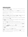
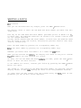
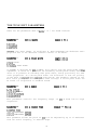
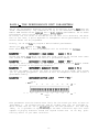
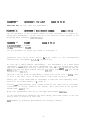
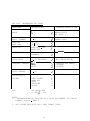
C
heetah
MULTI TIMBRAL
SWVTHESIZER MODULE
OWNERS MANUAL
Thank you for choosing the CHEETAH MS6 MULTI TIMEBAL SYNTHESIZER MODULE.
The MS6 uses traditional sound generation tchniques combined with state of the
art technology to bring you sounds with a richness and depth rarely found in
most synthesizers today.
Sounds are created using parameters which should be familiar to the vast
majority of synthesizer users, and are therefore easier to use than some other
methods of synthesizer programming.
To assure you that your MS~ will give you many years of enjoymt, please be
sure to read this owners manual carefully before attempting to operate it.
FEATURES
* Multi-timbral
-
any voice assignable to any one of 16 MIDI channels
* 320 ROM sounds
* 96 Non-volatile RAM sounds
* 64 User programmable performance memories
* Dual DC0 per voice
* Six voice polyphonic
* Velocity Sensitive
* Aftertouch (pressure) sensitive
* Dual ENV per voice
* Six 24 dT3 / octave VCF's
* Direct access patch change buttons
* Fully progrmble from the front panel
* LED display
* MIDI IN, OUT & THRU
1
CONTENTS
Page
FEATURES
1
GETTING STARTED
3
OPERATING THE MS6
3
CHANGING PROGRAM
4
CHANGING BANK
4
EDITING THE SOUNDS
6
TOCHANGE THE MIDI RECEIVE CHANNEL
7
TO CHANGE THE MASTER TUNING
7
PROGRAMMING THE MS6
7
WRITING A PATCH
8
THE TONE EDIT PARAMETERS
9
BANK 8 -THE PERFORMANCE EDIT PARAMETERS
24
THE UTILITY EDIT PARAMETERS
27
PATCH NUMBER CONVERSION TABLE
29
MIDI EXCLUSIVE DATA FORMAT
30
MS6 VOICE LIST
34
GETTING STARTED
The MS6 is a MIDI synthesizer module, which must be controlled by another MIDI
device.
Any MIDI controller such as a MIDI Master keyboard, MIDI Guitar, MIDI Drum
machine, MIDI Sequencer etc. will be suitable provided that it conforms to the
MIDI standard.
No sound will be produced by the MS6 unless a MIDI device of scme type is
connected.
Connect the MIDI IN socket on the rear of the MS6 to the MIDI OUT of your MIDI
controller.
Set your MIDI controller to transmit on MIDI channel 1.
Connect the Audio out socket on the rear of the MS6 to the audio input of a
suitable amplifier.
Next, insert the power connector to the mains sccket and switch on.
OPERATING THE MS6
when pCkyTer is supplied to the MS6, it automatically enters PLAY MODE, and Bank
1, Patch 11 is selected.
The Bank and Patch Number is shown on the display.
The number on the left of the display is the current Bank Number, and the one
on the right is the current Patch Number.
Playing any of the notes on your controller causes sound to be produced by the
Ms6. The sound produced is the one shun in the LED display.
A dot in the LED display will light whenever a voice is active. If you can't
hear any sound produced by the MS6, first check to see that the Ms6 is getting
the MIDI data, and then check your audio connections.
The MS6 is velocity sensitive, and will respond to velocity data if the patch
selected is programmed to do so.
Provided that the MIDI controller can transmit velocity data, altering the
velocity with which you play the MIDI controller will result in a corresponding
response from the MS6.
In this way it is possible to recreate some of the dynamic capabilities of real
instruments.
No effect will occur with non-velocity sensitive MIDI controllers.
CHANGING PROGRAM
The MS6 allows recall of over 400 different patches from memory. The MS6 uses 8
banks, most consisting of sixty four Patch Numbers, numbered 11 to 88.
Some manufacturers equipment does
not
this
method of
use
program
identification. A Patch Number conversion table is provided at the end of this
manual for ease of conversion.
To change sound, simply press any two number buttons on the front panel keypad.
For example, press the 2 key and then the 4 key. The display will show 24 as
the patch nm playing. Any combination of numbers between 11 and 88 may be
obtained.
Playing any notes on your MIDI controller will now play this sound from the
MS6. Try sane other patches such as 75, 88 and 32.
CHANGING BANK
&ce you have tried all the sounds in Bank 1, you may like to hear sane other
sounds in other banks.
Press the BANK / WRITE key at the bottom right of the keypad,
enter Bank 2.
and you will
You may nm play another 64 different sounds.
Press the Bank key again, and another 64 different sounds my be accessed.
There are 8 banks in the MS6.
L&en in Bank 8, pressing the Bank key returns you to Bank 1
Banks 1 to 5 are each banks of 64 ROM sounds.
Banks 6 and 7 are banks of RAM sounds.
Bank 6 has 64 sounds numbered 11 to 88.
Bank 7 has 32 sounds numbered 11 to 48.
Bank 8 is a bank of 64 performance memories.
Most of the performance memories in Bank 8 will be blank for you to program
your W configurations.
Many of the Ram sounds in banks 6 and 7 will appear to be identical to each
other, and to sounds in the ROM Banks 1 to 5. In most cases they will be slight
variations of sounds used to program the performance memories to give a Unison
detune effect. How this is done will be explained later in the manual.
You can reduce or increase the volume of the sound you have selected by
pressing the VOL UP or VOL DOWN buttons on the front panel keypad. Nhile you
press one of these keys, the display will show the current volume value for
that sound changing.
The maximum volume value is 63 and the minimum is 0. This volume setting is
only for the voice you are currently using, and will not be memorised, so
selecting the same patch number again will restore the volume setting to its
original value.
If you would like to store the sound at a new volume setting, that can be done
in EDIT mode which will be explained shortly.
Many users will find that all the sounds you will ever require are already
stored in the memory of the MS6. In that instance, you need not concern
yourself with most of the rest of this manual. If however, you wish to
experiment and create some sounds of your own, read on but first of all, try
editing sane sounds we've already made for you.
EDITING THE SOUNDS
As you can see frcxn the top panel, the MS6 has many different parameters which
nay be used for creating so&&.
Changing only one of these parameters may have an enormous effect. Changing
another may only have a slight effect.
The easiest way to see what the effect of these parameters are, is to edit a
sound of your choice, a parameter at a time, until the function of each
parameter is clear.
Select a sound you would like to edit.
'Ib enter EDIT mode, press the PLAY / EDIT button at the top right of the
keypad. The display will now show the parameter number on the left,- and the
current value of that parameter on the right.
In EDIT mode, the number keys select the parameter you wish to view, and not
sounds. The parameter and value displayed refers to the sound you selected
before you entered EDIT mode.
To change the value of the parameter you have selected, press the VALUE UP or
VALUE DOWN buttons. When a negative value is displayed, a dot will appear in
the display next to the value reading.
You may change as many different parameters as you like, and you do not have to
return to PLAY mcde to hear the effect of your changing values.
Play a note on your MIDI controller and listen as the sound changes while you
change values. The only time you need to enter PLAY mode is to change Bank and
Patch numbers.
To return to PLAY mode, simply press the PLAY / EDIT button once more. The
display now shms Bank and Patch numbers again.
The PLAY / EDIT button is used whenever you wish to switch between PLAY and
EDIT modes.
In Banks 1 to 7, the parameters displayed are the Tone edit parameters, as
detailed on the left of the top panal of the MS6.
In Bank 8, the parameters displayed are the Performance edit / Utility edit
parameters, as detailed on the right of the top panel of the MS6.
Bank 8 is the Bank you need in order to change the MIDI receive channel, Master
tuning or load and save memory data.
TO CHANGE THE MIDI RECEIVE CHANNEL
Select Bank 8 and then enter EDIT mode.
Select parameter 81 using the number buttons, and the Basic MIDI receive
channel number is displayed as the value on the right of the display.
Use the VALUE UP or VALUE DC;WN buttons to change the MIDI channel to the number
you require. The default is channel 1.
Return to PLAY mode and select other sounds you wish to play.
TOCHANGE THE MASTER TUNING
Select EDIT mode while in Bank 8.
Select parameter 84 to change the Master tuning of the MS6. The master tuning
may be altered to +31 or -31 which corresponds to +93 or -93 cents. The default
setting is 0.
PROGRAMMING THE MS6
When you edited the sounds earlier, the changes were not stored, so the sound
was reset to its original setting when you selected its Patch number again.
This was only temporary editing of the sounds.
To make a permanent change to a sound, you must store the modified or new sound
in memory.
Banks 6 and 7 are RAM sounds and can be stored with any changes you like into
their current Patch number, or another Patch number.
Sounds in Banks 1 to 5 are ROM sounds and cannot be written into.
However, sounds in Banks 1 to 5 can be copied into Banks 6 and 7 so that your
changes can be memorised.
7
WRITING A PATCH
Edit a sour-d.
When you are satisfied with any changes, press the BANK / WRITE button.
The display clears to await the new Bank and Patch number you would like this
sound to be.
This may be the same Bank and Patch number (provided you are in Banks 6 or 71,
in which case, the modified sound will be stored in its current location with
all the changes memorised.
You may choose another Bank and Patch number, in which case the modified sound
will be stored in that new location, deleting the previous sound in that other
location automatically.
Enter the Bank number by pressing the corresponding number key.
Enter the Patch number by pressing the corresponding number keys.
Remember you cannot write into Banks 1 to 5. These are RCCl Banks.
When you have entered the n&rs, the display will flash to ask you to confirm
that the numbers you have selected are correct.
If they are not the Bank and Patch nmrs you want, press the PLAY / EDIT
button to abort the Write function.
If the numbers are correct, confirm your choice by pressing the BANK / WRITE
button once again.
The sound is now stored in the Bank and Patch number you selected, and the
display returns to EDIT mcde showing the value of the last parameter selected.
In order that you may create your own sounds using the Ms6, each of the
parameters you can use will now be explained.
THE TONE EDIT PARAMETERS
These are the parameters used in Banks 1 to 7 for sound creation.
PARiwEmm 11
DCOASHAPE
RANGFao!m2
O=.FQ_AFE
l='IIKCANGLE
2=SAWl'CGTH
Selects the wave shape of oscillator A. Each waveshape has different sonic
properties due to the different harmonic content of the waves.
Pm 12
DCOAPULSEWIDTH
RAMx1!ro15
l=THIN PULSE
8=SQWRE
15=INVERSE THIN PULSE
If SQUARE is selected for DC0 A SHAPE, this control sets the pulse width of the
squarewave. A value of 1 produces an extremely narrow pulse width, while a
value of 15 produces an extremely wide pulse width, having practically the same
sonic properties as a narrow pulse width. The difference is that the polarity
of the wave is c&nged when ccxnpard with narrow. The harmonic content of the
wave varies greatly at different pulse width settings. A narrow pulse width can
be useful for harpsichord or woodwind sounds.
PARIwEmR 13
IXDARANCX
RANGEom3
O=mOCI'AVE
l=IQW/MID OCTAVE
2=HIGH/MID OCTAVE
3=HIGH OCTAVE
This parameter controls the frequency range
frequencies.
PARAMExm 14
DCOACOARSETLJIW
of DC0 A from low to high
RANm -12 To +12
O=CENTRETUNE
-12=-12 SEMITONES DFTUNE
+12=+12 SEMITONES DETUNE
This parameter allows the pitch of DC0 A to be adjusted by up to 12 semitones
from the centre frequency, in semitone steps.
9
PARACEER 15
ECOALE'ODEIE'TH
RATKXOTo63
@NO LFO PITCH MOD
63=MAXLFOPITCHMOD
This parameter determines the amount of effect that the LFO has upon the pitch
of IX0 A. -When used, this function can create a vibrato effect on DC0 A. The
rate of pitch modulation is determined by the LFO frequency. See parameter 63.
PARNWXFR 16
DCOAJSWDEIP!t'H
RANGEi -63 To +63
-63=M?x NEGATIVE PITCH MOD
O=NO PITCH MOD
+63=MAX POSITIVE PITCH MOD
This controls the effect of the envelope on the pitch of DC0 A. If negative
values are used, the pitch of DC0 A will be lowered and then returned to its
original pitch. If positive values are used, the pitch of DC0 A will be raised
and then returned to its original pitch. How long this pitch change takes is
determined by the ADSR settings of the envelope used. See parameter 21.
PARAMEmm 17
DCOAPWMDEIPTH
RAN(;EO!ITQ63
o=No PULSE WIDTH MOD
63=MAXPUISEWIM'HM3D
The pulse width can be modulated by an envelope or a separate PWM LFO. Use
parameter 22 to select which one you use, and parameter 17 to control the
amount you wish to vary the pulse width by. Care must be taken with the pulse
width when the oscillators are in sync (see parameter 24). This parameter is
useful for making a square wave on DC0 A sound richer.
PARAMElw 18
DCOAEENDDEETH
RANGIZ 0 To +12
O=NZ PITCHBEND
+12=MAX POSITIVE PITCH BEND
Use this parameter to control the effect of your MIDI controllers pitch bend
wheel on the pitch of DC0 A. This is the amount of bend when the wheel is moved
to its greatest extent.
10
I?ARAME;TER 21
D(30AENVS-
RANGEJloR2
l=ENv 1
2=lmv 2
Select 1 to make ENV 1 control the DC0 A pitch modulation effect set in
parameter 16. Select 2 to make ENV 2 control the DC0 A pitch modulation effect
set in parameter 16.
Pm 22
DCOAPL%MSEXEKX
RANGEooR1
O=LOW FREQUENCY CONTINUOUS - SET BY PWM RATE (SEE PARAMETER 48)
~=ENVELOPEAS sm BY PARAMIzTkx 21
Use this parameter to select whether the pulse width mcdulation is controlled
by the PWM rate parameter (481, or by the envelope selected in parameter 21.
PARAME;TER 23
DCOABEND_
RANeEom1
O=PITCH BEND CONTROLLED BY PRESSURE
~=PITCH BEND CONTROLLED BY PITCH BEND WHEEL
Select 1 for normal operation of pitch bend on IX0 A. If you have a MIDI
controller which transmits pressure (aftertouch) data, you may wish to select
0, and pitch bend DC0 A by applying pressure instead.
Pm 24
DcoASYNCTODaoB~/OJ?F
RANGEooR1
O=DCOANOT SYNCEDTOJXOB
l=DCO A SYNCED TO DC0 B
In this parameter, you can synchronise DC0 A to DC0 B. This effect is very
useful for creating lead synthesizer sounds which really 'cut through'.
11
PzARmEnm 31
DCOBSHAPE
o=sQuARE
l=TFUANGLE
2=SAWIWIH
3=NOISE
Selects the wave shape of oscillator B. Bach waveshape has different sonic
properties due to the different harmonic content of the waves. The noise
setting is useful for adding a touch of 'breathiness' to woodwind and other
sounds.
Pm 32
DCOBPUISEWIM'B
RANGE 1 TO 15
l=THIN PULSE
8=SQUARB
15=INVERSE THIN PULSE
If SQUARE is selected for DC0 B SHAPE, this control sets the pulse width of the
squarewave. A value of 1 prcduoes an extremely narrow pulse width, while a
value of 15 produces an extremely wide pulse width, having practically the same
sonic properties as a narrow pulse width. The difference is that the polarity
of the wave is changed when capared with narrow. The harmonic content of the
wave varies greatly at different pulse width settings. A narrow pulse width can
be useful for harpsichord or w&wind sounds.
PARAMEIER 33
DCOBRANGJX
RANaoTo3
o=LcxnlOCFAVE
l=LOW/'MID OCTAVE
2=HIGH/'MID OCTAVE
3=HIGH OCTAVE
This parameter
frequencies.
PARMEFER 34
controls the frequency range
JXOBCDARSETUNE
of DC0 B from lcw to high
RANGE -12 m +12
OXENTRE'IUNE
-12=-12 SEMITONES DETUNE
+12=+12 SEMITONES DETUNE
This parameter allows the pitch of DC0 B to be adjusted by up to 12 semitones
from the centre frequency, in semitone steps.
12
PARAMETER 35
DCOBLFODEX’TH
RATGlZO!t’O63
O=NO LFO PITCH MOD
~~=MAx LFO PITCH MOD
This parameter determines the amount of effect that the LFO has upon the pitch
of DC0 B. When used, this function can create a vibrato effect on DC0 B. The
rate of pitch modulation is determined by the LFO frequency. See parameter 63.
PARAMplER 36
DCOBlSlVDlSTH
RAJ!KX - 6 3 To +63
-63=M%x NEGATIVE PITCH MOD
o=NO PITCH MOD
+63=MAx POSITIVE PITCH MOD
This controls the effect of the envelope on the pitch of DC0 B. If negative
values are used, the pitch of IX0 B will be lowered and then returned to its
original pitch. If positive values are used, the pitch of DC0 B will be raised
and then returned to its original pitch. How long this pitch change takes is
determined by the ADSR settings of the envelope used. See parameter 41.
PAFaummR 37
DC0BEWMDEl?!l!H
RANG.EOT063
o=No PULSE WIDTH MOD
63=MAXPUISEWIDI'HMOD
The pulse width can be modulated by the main LFO or a separate Pm LFO. Use
parameter 42 to select which one you use, and parameter 37 to control the
munt you wish to vary the pulse width by. Remember that at its maximum
setting (depending on the pulse width you have select&) the pulse width rray be
varied so greatly that the wave gets so thin that it disappears at times! This
parameter is useful for making a square wave on DC0 B sound richer.
PARAME;Tw 38
DCCIBBENDDEX’TH
RANGE 0 TQ +12
O=NO PITCH BEND
+12=MAX POSITIVE PITCH BEND
Use this parameter to control the effect of your MIDI controllers pitch bend
wheel on the pitch of DC0 B. This is the amount of bend when the wheel is moved
to its greatest extent.
13
PARAMExm 41
DCOBENVSELECT
l?A?smlQR2
l=ENv 1
2=ENV
2
'
Select 1 to make ENV 1 control the DC0 B pitch modulation effect set in
parameter 36. Select 2 to make ENV 2 control the DC0 B pitch modulation effect
set in parameter 36.
Pm 42
IlCOBl%MSELKC
RA?SFlOORl
O=LQW EREQUBT9ZY CONTINUOUS - SET BY PWM RATE (SEE PARAME'I'ER 48)
l=ENVE%OPE AS SET BY PARAMETER 41
Use this parameter to select whether the pulse width modulation is controlled
by the PWM rate parameter (481, or by the envelope selected in parameter 41.
Pm 43
DC0BBENDSEZEK.X
RANGF#o!co1
O=PI'ICH BEND CONTROLLED BY PRESSURE
l=PITCHBEND CONTROLLED BYPITCHBBNDWHEEL,
Select 1 for normal operation of pitch bend on DC0 B. If you have a MIDI
controller which transmits pressure (aftertouch) data, you may wish to select
0, and pitch bend DC0 B by applying pressure instead.
14
Pm 44
D0Z)BFINEm
-31=93 CENTS NEGATIVE DETUNE
O=NO DFTUNE
+3l=93 CENTS POSITIVE DEIFUNE
RANGE -31 To +31
(3 CENTS PER COUNT)
With this parameter you can adjust the pitch of DC0 B by a slight amount to be
sharp or flat relative to the pitch of DC0 A. This creates a very pleasant
chorus type effect due to the beat frequency produced when both DCO's are used.
Smaller values generally produce the most pleasant effect. See the section on
Perfomnce Edit Parameters, which will use this parameter to create a Unison
detune effect.
PAR_ 45
DCOATOBMIX
l?ANcx -31 To +31
-31=DCO B ONLY
O=EQUAL AMOUNT OF DC0 A AND DC0 B
+31=DCO A ONLY
This is the parameter which mixes the outputs of both oscillators and a llows
you to control the relative levels of each in the output signal. When noise is
selected on DC0 B, this parameter is useful for reducing the munt of noise in
the output.
PV46DCOATOBmENVDEPTH
RANGE -63 TO +63
-63=MAX SWEEP TO DC0 B BY ENVELOPE
O=No SWEEP BY ENVELOPE
+63=MAX SWEEP TO DC0 A BY ENVELOPE
This parameter can be used to autocratically adjust the oscillator mix according
to the envelope ADSR settings of the envelope selected in parameter 47. This
parameter is used to produce Wave Mix sounds, where the oscillator mix is fully
to one oscillator at the start of the envelope, and then changes to the other
oscillator as the sound progresses. Many interesting effects may be obtained by
selecting different waveforms for each oscillator, causing the sound to change
from one type to another. Some examples of Wave Mix sounds are in the ROM
Banks.
Pm 47
JXJOATDBMIXEM7SELM3T
RANGElOR2
l=MIX CONTROLLED BY ENV 1
2=MIXCONTROLLED BY ENV 2
Select which envelope you wish to sweep the DC0 A to B mix with this parameter.
15
PAEWEXER 48
DCOAANDBPWMRATEl
RANCXO!I'O63
O=SLOWFST IQW FREQ. PWM RATE
63=FASTEST LOW FRFQ. PWM RATE
This is the parameter which controls the rate that the oscillators pulse width
varies when selected by parameters 22 & 42.
PARAMJnm 51
FILTER CvrrlFF FMQUEKY
RANGJloTo99
O=LQWEST FREQUENCY (FILTE R CLOSED)
99=HICHEsT FREQUENCY (FILTER OPEN)
The Filter is one of the most important features of a synthesizer, having an
enormous effect upon the sound produced by the oscillators. The filter
determines whether a sound is dull or bright, and can have its effect varied by
several other controls which produce a complex resultant effect on the sound
output. At high settings, little or no effect on the sound will be heard. At
medium settings, the higher frequencies or harmonics will be reduced leaving
the oscillators sounding smother and less bright. At minimum settings, a dull
sound will be produced, or even no sound at all. The best setting for this
parameter varies greatly according to the sound required. You will be using
this parameter a great deal.
P- 52
FILTERFEDN?NX
RANGJXOTo63
O=NO FILTER RESONANCE
63=MAXIMUM FILTER RESONANCE
This parameter enhances the sound at the frequencies closest to the filter
frequency, resulting in an effect which can produce a ringing sound. Useful for
special effects and scme woodwind sounds which depend on resonance.
PARAMGIW 53
FILTWLFODEPTH
RANGIZOT063
o=NQ FILTER LFO DEPTH
63=MAX LFO FILTER DEPTH
Using this parameter, the f'ilter can be opened and closed autcmatica lly by the
mainLFO.
16
PARAME;TER 54
FILTER ENV DEPTH
RANCX -63 !I!0 +63
-63=MAX NEGATIVE FILTER ENVELOPE DEPTH - CLOSES filter
O=No FILTERENV DEPTH
+63=MAx POSITIVE FILTER ENVEI.OPE DEPTH - OPENS filter
This parameter can vary the filter frequency in time with the ADSR settings of
the envelope you choose to control it. Negative values will open the filter
with the envelope. Positive values will close the filter with the envelope.
PARMETER 55
FILTERPRESSUREDEXTfl
RANCZ -63 TO +63
-~~=MAx NEGATIVE FILTER PRJXSSURE DEPTH - opens filter
O= NO FILTER PRESSURE DEPTH
+63=MAX POSITIVE FILTER PRESSURE DEPTH - closes filter
If your MIDI controller sends pressure (aftertouch) data, you can open or close
the filter with this parameter.
PARAMElER 56
FILTWENVSELEICT
RANGElOR2
l=ENV 1 CONTROLS FILTER CUtOFF
2=ENV 2 CONTROLS FILTER CUTOFF
Select which envelope you wish to use to vary the filter cutoff frequency.
parameter 54.
PARAMJsm 57
FILTERKEXFDLU3W
See
RANGIZOTO63
O=NO FILTER KFJBoARD Fo~mw (CUTOFF FREQ. REMAINS CONSTANT ACROS S NOTE RANGE)
63=MAX FILTER KEYBOARD FOLLOW (CUTOFF FREQUENCY RISES AS HIGHER NOTES ARE
PLAYED)
This parameter is used to avoid high pitched notes from being cut off by the
filter and so opens the filter as the notes played get higher.
17
PARMETER 61
WOSHAPE
RArxxoTo3
O=TRIANGLELFOWAVEFORM
l=SAWI'OGTH LFO WAVEFORM
2=SQUARELFO~AVEFORM
3=RAND@l LFC WAVEFORM
The Low Frequency Oscillator is used to modulate the main oscillators and other
parameters which make up a sound on the MS6. If the LFO is used to modulate the
pitch of an oscillator (see parameters 15 & 35), a vibrato effect can be
obtained. A triangle wave LFC will smoothly alter the pitch of an oscillator up
and dm. A sawtooth wave will alter the pitch smoothly up and then rapidly
back to the original pitch. A square wave will change rapidly from sharp to
flat relative to the original pitch. A random wave will alter the pitch
randomly. The LFO can alter other parameters such as filter settings, and the
effect upon the parameter will vary according to the waveform used.
P- 62
m DEIAYTIIW
RANCXOTo63
O=No LFO DELAY FROM NOTE ON
63=MAXLFODEXAY FROMNCYTEON
This parameter controls the time it takes for the LFO to affect the other
parameters you have select. A setting of 0 means the LFC will act as soon as
you play a note. A higher setting will increasingly delay the LFo's effect frcxn
note on.
P- 63
RAIKXOTo63
WFREQUENCY
O=MIN LIX FREQUENCY
63=MAX LFO FREQUENCY
Vary the speed of the LFO with this parameter.
P- 64
liEOPITCH~-
RANQ3OOR1
O=MJD WHEEL CQJI'ROLS LFO PITCH MOD
l=PRESSURE CONTROLS LFO PITCH fvlOD
Normally, the modulation wheel is used to produce LFO pitch modulation when
performing. The MS6 lets you use pressure data from your MIDI controller to do
this instead if you so wish.
P- 65
I.JWPIlXXI'CODEETH
RANao!l!o15
O=NO LFO PITCH MOD
15=MAX LFO PITCH MOD
This parameter sets the amount of LFC pitch modulation you require.
18
PARAMExm 66
LF'O FILTER MOD SELECT
RANmooR
O=mD WHEZL CONTROLS LFC FILTER MOD
l=PRESSURE CONTROLS LFC FILTER MOD
Normally, the modulation wheel is used to produce LFO filter modulation when
performing. The MS6 lets you use pressure data from your MIDI controller to do
this instead if you so wish.
P- 67
LFO FILTER MDDULATION
RANGEoTO15
O=NO LFO FILTER MOD
15=MAX LFO FILTER MOD
This parameter sets the amount of LFO filter modulation you require.
PAEuummR 68
VCAVOWME
RANGEO'I'O63
O=No OUTPUTFR@'lVCA=MINIMUMGAIN
63=MAX OUTPUT FROM VCA = MAXIMUM GAIN
The Voltage Controlled Amplifier controls the output level of
parameter is useful for adjustingdifferentsounds so that their
are similar. This parameter is also adjusted by the VOL UP and
when not in EDIT MODE, in which case the volume setting will not
when you select another sound. Use this parameter in EDIT MODE to
at a certain volume setting.
Pm 71
EWl ATTACKTIME
the MS6. This
output levels
VOL DOWN keys
be remembered
store a sound
RANGEO!I!O63
O=FASTEST ENVl ATTACK TIME
63=SIXWEST ENVl ATTACK TIME
This parameter controls the time it takes Envelope 1 to reach the output level
set in parameter 68. The envelope settings are extremely important in shaping
the sound output from a synthesizer. The envelopes can be used to vary the
volume, filter setting, pulse width, pitch and other parameters. A short attack
time is useful for percussive and plucked sounds. A longer attack time is
useful for brass and string sounds.
P- 72
ENVlDExaYTIME
RANGEOTo63
O=FASTl%STENVl DECAY TIME
63SLWEST ENVl DECAY TIME
Once the attack is complete, the envelope will begin to decay or diminish. How
long this takes is determined by this parameter.
19
PARAMExm 73
ENvl SUSTAINLEVELI
RANGEOT063
O=NO ENVl SUSTAIN LEVEL
63=MAX ENVl SUSTAIN LEVEL
If a note is kept pressed on your MIDI controller, this parameter sets the
envelope output level while the note is pressed.
PARAMETER 74
ENVlRELFASE TIME
RANGEOT063
O=FASTEST FNVl RELEASE TIME
63=SLQWEST ENVl RELEASE TIME
Once you have released a note, this parameter controls the length of time for
the envelope to die away.
PmAME2ER 75
RANGEoORl
ENV1susrAINSwI!IcH
O=ENVl SUSTAIN PHASE IGNORED
l=ENVl SUSTAIN PHASE CARRIEDOUT
This parameter selects whether a key held dmn on the MIDI controller is obeyed
by ENV 1, or instead the envelope goes straight into the Release phase after
completing the Decay phase. The latter is useful for percussive sounds.
P- 76
ENvlKJZYFoT;LMw
RANmoTo15
O=No ENVl KEYBOARD FOLL@J (ENV CONSTANT ACROSS KEY RANGE)
15=MAX ENVl KEYBOARDFOLLOW (FNVTIMEDECRFASEASNOTEPITCHRISES)
This parameter can shorten the Decay and Release tims of FNVl for higher
frequency notes. This is useful for piano sounds.
PAEvwmER 77
ENVlVEWCITYTDAMPLITUDESENSITJS7ITY
RANGEOTO 15
O=NO SENSITIVITY TO NOTE VEXCCITY
(ENVl ALWAYS AT MAX LEVEL)
15=MAx
SENSITIVITY
TO NOTE VELOCITY (ENVl AMPLITUDE IS EXPONRNTIALLLY
PROPORTIONAL TO NOTE VFLOCITY)
Use this parameter to tailor the effect of key velocity on the output level of
ENVl.
20
P- 78
vEux3ITYToA!rr~~sENsI!l!Ivrl!Y
RANGEom15
O=NO ATTACK SENSITIVITY TO VELCCITY
(ATTACK TIME SET BY ENVl ATTACK PARAMETER)
15=MAX ATTXK SENSITIVITY TO VELOCITY
(ATTACK TIME VARIES IN RELATION TO KEY VELOCITY UP TO SFI"TING ON ENVl ATTACK
PARAMETER)
This parameter allows the attack time of ENVl to be lengthened by notes with
low velocity values. A key strike of maximum MIDI velocity will not shorten the
attack time beyond that programmed in parameter 71.
21
P- 81
Ew2A!l?mcKTIME
RANGEOTo63
O=FASTEST ENV2 ATTACK TIME
63=SIQWEST ENV2 ATTACK TIME
This parmter controls the time it takes Envelope 2 to reach the output level
set in parmeter 68. This envelope can be used to vary the filter setting,
pulse width, pitch and other parameters.
P- 82
EXV2DEIcAYTlME
RANGEOm63
O=FASTEST ENV2 DECAY TIME
63=SLGwEST ENV2 DECAY TIME
Gnoe the attack is ccmplete, the envelope will begin to decay or diminish. Hm
long this takes is determined by this parameter.
PAFWWIXR 83
ExW2!mSTAINLEvEL
BOTo63
0=NO EM72 SUSTAIN LEVEL
63=MAX ENV2 SUSTAIN LEVEL
If a note is kept pressed on your MIDI controller,
envelope output level while the note is pressed.
P- 84
EINWRELEASET~
this parameter sets the
-0To63
O=FASTEST EW2 RELEASE TIME
63=SLOWEST ENV2 RELEASE TIME
Once you have released a note, this parameter controls the length of time for
the envelope to die away.
P- 85
EW2SUS!l!AINSWI!CCH
I?ANGFnOORl
0=ENV2 SUSTAIN PHASE IGNORED
1=ENV2 SUSTAIN PHASE CARRIED OUT
This parameter selects whether a key held dmn is obeyed or ignored by ENV 2.
If the sustain phase is ignored, the envelope goes straight to the Release
phase after ccmpleting the Decay phase.
22
PARzwnER 86
Ew2KExF
FaNGJzom15
O=NO ENV2 KEYBOARD FOLLOW (BNV CONSTANT ACROSS KEY RANGE)
15=MAX ENV2 KEYBOARD FOLm (ENV TIME DECREASE AS NOTE PITCH RISES)
This parameter can shorten the Decay and Release times for ENV2 on higher
frequency notes.
O=NO SENSITIVITY TO NOTE VELOCITY
(ENV2 ALWAYS AT MAX LEVEL)
15=MAx
SENSITIVITY
TO NOTE VELOCITY (ENV2 AM!?LITUDE IS EXPONENTIALLLY
PROPORTIONAL TO NOTE VELOCITY)
Use this parameter to tailor the effect of key velocity on the output level of
EN%?.
PAFuwEma 88
WT.QCITY!I'OATl?iYXXT7MESENsITM!I'Y
RANcxo!ro15
O=NO ATTACK SENSITIVITY TO VIZLOCITY
(ATTACK TIME SET BY ENV2 ATTACK PARAMETER)
15=MAX ATTXK SENSITIVITY TO VELOCITY
(ATTACK TIME VARIES IN RELATION TO KEY VELOCITY UP TO SETTING ON EM72 ATTACK
PARAMETER)
This parameter allows the attack time of ENV2 to be lengthened by notes with
low velocity values.
Now all the parameter functions and ranges have been explained, you can start
to create your cwn new sounds. If any aspect of the parameters is unclear, try
changing the value of the parameter in question on a sound already made. Its
function should scan beccxne clear.
Use banks 6 and 7 to store your own sounds.
23
BANK 8 - THE PERFORMANCE EDIT PARAMETERS
One of the outstanding features of the MS6 is its ability to play more than one
sound simultaneously. Any combination of up to six different voices from the
ROM or RAM sounds can be ccmbined into a Multi-timbra performance. 64 of these
performances can be stored in the memory of the MS6.
Of course, the six voices of the MS6 do not all have to be different, and where
this is the case, a split keyboard or monophonic unison performance with or
without detune can be programmed.
Firstly, let us see hm to program a Multi-timbral performance.
Ensure you arein Bank 8 of theMS6.
Enter EDIT mode, and a set of parameters will be available as follows:
PARAMETW 11
lX?l5XuMHVr1BANKNuIWSR
RANtXlTO6
Choose the Bank fram which you want the first sound to be called from. Note
that sounds in Bank 7 cannot be used in a performance memory.
FUWZ 11 TQ 88
PAWMEJZR 12
IN!STR~lToNEN[MBER
Choose the Patch (Tone) number of the sound you require from the Bank of sounds
you have selected in the previous parameter.
PAWMEXYB 13
rNsJBuMEWr lBKJM3ER OFFICES
RANGEOTo6
Set here the number of voices you wish to allocate to this sound. This allows
you to program polyphonic sections as well as monophonic sections within a
performance memory.
PAEuusnm 14
IJG!LEX~ 1 -LlMIT
0
c-2
MIDI NOTE No.
12
24
36
C-l
co
Cl
RANGE CO To b7
48
60
72
84
96
108
I20
127
cz
c3
c4
c5
C6
c7
C8
c9
MIDDLE
‘C’
This parameter sets the bottom note limit for the sound you wish to have as
Instrument 1. CO is MIDI note 24, and b7 is MIDI note 119. C3 is middle C,
which is MIDI note 60. Set in conjuction with the next parameter for the top
limit, it is possible to split and layer the MIDI controllers keys into zones
capable of playing different sounds and layered sounds even if no key split
facility exists on your MIDI controller.
24
PAEtmmmR 15
IN=-lToPLIMIT
RAWEZCOTOb7
This sets the top note limit for Instrument 1.
Use this parameter to set the MIDI channel you wish Instrument 1 to respond to.
Using this parameter, you may have up to six different sounds playing on six
different MIDI channels simltaneously.
PARAMEmm 17
VOLWE
RAN(;EOTol5
O=MIN INSTRUMFXT 1 VOLUME
15=iWX INSTRUMENT 1 VOLUME
Use this parameter to adjust the volume of Instrument 1.
Parameters 21-27, 31-37, 41-47, 51-57, & 61-67 refer
functions for instruments 2,3,4,5 & 6 respectively.
to
the
corresponding
To set up a Multi-timbral performance, set Instrument 1 to a bass sound
(parameter 11&12) using one voice (parameter 13). Set the bottom note limit
(par.141 to its lowest setting, and the top limit to a lowish setting such as
b3 (par.15). Put the MIDI channel setting (par.16) on channel 1, and the volume
setting on 15 (par.17).
Then put a string sound on Instrument 2 using four voices with a bottom limit
of C4 to a top limit of b5, on MIDI channel 1 and volume setting 15.
Lastly put a Sync lead sound on instrument 3 using the last remaining voice,
from C6 to C8 on MIDI channel 1 & volume 15.
You may new simultaneously play a bass sound at the lower end of your MIDI
controller, a string sound in the centre, and a lead sound at the top end.
Sounds good, dcesn't it?
Write your performance into one of the empty performance maories.
If you had difficulty preparing the above setup, edit some others to get the
hang of what is going on in each case.
Scme examples of different performances are already in memory.
25
To take a sound and play it in MONO made, set up a performance as follms:
Select the sound you require, and use this sound for all six instruments (one
voice per Instrument), playing over the same note range on the same MIDI
channel.
You may then play all six voices (producing the same sound) on one note. This
technique is useful for powerful bass and lead sounds. In this monophonic
setting, only one note at a time may be played however. Priority is given to
the last note pressed.
Many of you will have already guessed that it is possible to have a different
sound for each Instrument in a performance like this. You may play up to six
completely different sounds on one note. If you choose six suitable sounds it
can sound devastating. Be careful though, it can also sound awful if you don't
choose your sounds carefully. Some Multi-timbral mono performances are already
prepared in Bank 8.
A variation of this is used for a Unison (mono) detune effect.
First select the sound you would like to use.
Then copy the voice into a spare memory in Bank 6. Next edit the DC0 B fine
tune (parameter 44), to a new value a couple of counts away from its original
setting. Store this edited sound in Bank 6 next to the original sound. Next,
edit the DC0 B fine tune a further couple of counts from its original setting,
and store this sound in hank 6 next to the last edited sound you stored. Keep
changing the DC0 B fine tune and storing subsequent voices until you have six
nearly identical sounds stored in Bank 6, with the only difference being each
sound having a different DC0 B fine tune setting.
Next create a Multi-timbral performance using those six sounds in mono mode.
The result will be six voices all slightly detuned playing in unison, and
sounding very pmerful indeed. A number of these performances may be found in
Bank 8, and their component detuned sounds in Bank 6.
THE UTILITY EDIT PARAMETERS
The Utility edit parameters are also found in Bank 8 EDIT mode, and are used
for general functions which affect the whole synthesizer. Each of the functions
is explained below. Note tl?at unlike the other parameters, these parameters do
not require their settings writing into memory. They are automatically
remembered, even after the MS6 is turned off.
PARAMEmR 71
!Z?WE!LWEIMEIWRY
Select this parameter to dump the contents of Banks 6 & 7 via the MIDI OUT to
another Ms6 or to a MIDI data storage device. Select parameter 71, which shows
St (save tones), and when you are ready to transmit the data, press the VALUE
UP button. The St disappears for a few seconds while the MIDI data is being
sent, and then dn (done) appears to show that the dump has been carried out.
P- 72
zsfu?l3-ME7!4mY
This function dumps all the performance memories in Bank 8 via MIDI. SP (save
performance) is displayed. Press the VALUE UP key to save the performance
memories. The display shows dn when saving is canplete.
PARAMErm 73
ILXDloNEMEMDRY
Select this function when you wish to load a new selection of RAM sounds via
MIDI into Banks 6 & 7. The new sounds will overwrite the existing sounds in
Banks 6 and 7. The display shows It (load tones). Press the VAILJE UP key and
the It disappears until the MIDI data has been sent, when dn appears to confirm
the data has been received. Press the EDIT key if you need to escape from this
function once you have pressed the VALUE UP key.
PAFImmIm 74
UMDP-MEMOIZY
Select this function when you wish to load a new selection of performance
memories via MIDI into Bank 8. The new memories will overwrite the existing
memories in Bank 8. The display shms 1P (load performances). Press the VALUE
UP key and the 1P disappears until the MIDI data has been sent, when dn appears
to confirm the data has been received. Press the EDIT key if you need to escape
from this function once you have pressed the VAILJE UP key.
27
PARMEtER 81
BASIC~IVEMIDI~
FMKZOT016
O=@lNI ON
l=CHANNFL 1
16=C=L 16
You have already seen this parameter before, but have not used Omni mode.
In Omni mode, the MS6 will respond to MIDI data received on any MIDI channel.
Any other setting, ar-d the MS6 will respond to data on that corresponding MIDI
channel only.
Note that the Multi-timbral performance memories are unaffected by this
setting, and will receive data according to the parameters in their memory.
This MIDI channel setting applies only to single sounds played in POLY mode.
P- 82
@MIDI OVERFLOW OFF
l=MIDI OVERFLOW ON
One excellent feature of the MS6 is the MIDI overflow function. If this
function is selected, and all six voices are busy being played, any additional
notes over the six the MS6 can play at one time are retransmitted via the MIDI
CUT socket to a second MS6 synthesizer module. In this way, two MS6's can
produce a 12 note polyphonic synthesizer when the first is set to MIDI
overflow. Three MS6's gives 18 note polyphony. Imagine additional MS6's
connected to produce a monster set-up capable of playing dozens of notes and
dozens of different sounds simultaneously. This can be reality if you get scme
more MSG's!
PARAME=ITER 83
CALIBRATEDCO'S
The Digitally Controlled Oscillators in your MS6 have already been calibrated
before the unit left the factory, and will remain stable in normal use. Should
you at any time feel that you would like to re-calibrate the DCO's to ensure
accurate waveforms, before a recording session for example,select
this
function. Cl is displayed until you press the VALUE UP key, when the MS6 will
begin to calibrate both oscillators in each voice, first at low frequencies,
and then at high frequencies. This process takes a minute or so, and cannot be
stopped once started. When calibration is complete, dn is displayed to confirm
this.
Pm 84
!IwrALlX7c!R~TuNING
RAJZE -31 To +31
-31 = -93 CENTS
0 = A=440Hz
+31 = +93 CENTS
When playing with other instruments, you may wish to tune the pitch of the
whole MS6 to that of another instrument. Use this function to adjust the total
MS6 tuning.
28
PATCH NUMBER CONVERSION TABLE
PRo(;.Kb.
PATCH
PRoG.No.
PATCH
1
11
12
13
14
15
16
17
la
21
22
31
32
33
34
35
36
37
38
39
40
47
48
51
52
53
54
55
56
57
58
12
13
14
15
16
17
la
19
20
23
24
25
26
27
28
31
32
33
34
41
42
43
44
45
46
47
48
49
50
61
62
63
64
65
66
67
68
71
72
21
22
23
24
25
26
27
28
29
30
35
36
37
38
41
42
43
44
45
46
51
52
53
54
55
56
57
58
59
60
73
74
75
76
77
78
al
a2
a3
a4
61
62
63
64
a5
86
a7
88
2
3
4
5
6
7
a
9
10
11
29
MIDI EXCLUSIVE DATA FORMAT
On Initiating a SAVE TONE MEMORY or SAVE PERFORMANCE MEMORY
the MS6 will transmit a data dump with the following format.
Note :
X specifies undefined bits. When processing this dump data mask these
undefined bits.
TONE MEMORY
HEADER
-----Byte No
-------
Value
-----
Description
1
2
3
4
5
11110000
00110110
00000010
00000000
00000000
EXCLUSIVE
CHEETAH MARKETING I.D. CODE
PRODUCT DESIGN CODE
MS6 SYNTH MODULE DATA PACKET
TONE DATA IDENTIFIER
Certain parameters ( Such as DC0 A LFO depth ) will be split into two
bytes. If this is the case the first byte will contain the most significant
bit or bits of that parameter. The range will be specified for BOTH bytes.
Those parameters having a NEGATIVE value (Such as DC0 A to B MIX ) will again
be split into two bytes. When the two bytes are assembled into one, the first
byte is the most significant Nybble. The most significant Nybble is
redundant in all cases. The format is :FF - hex -1
FE - hex -2
FD - hex = -3
etc.etc.
q
q
Byte No
Value
-----
Description
--_--_-----
6
0000XXSS
DC0
DC0
DC0
DC0
DC0
DC0
DC0
7
8
9
ooooxxss
oooowwww
oooowwww
10
11
12
13
14
15
16
17
18
19
20
21
22
23
24
25
26
27
28
29
30
31
32
33
34
35
36
37
38
39
OOOOXXRR
OOOOXXRR
0000xxLL
OOOOLLLL
0000xxLL
OOOOLLLL
OOOOEEEE
OOOOEEEE
OOOOEEEE
OOOOEEEE
OOOOMMMM
OOOOMMMM
oooocccc
ulJu0cccc
0000000P
0000000P
0000cCcC
0000Cccc
OOOOFFFF
OOOOFFFF
0000000Y
00000022
OOOOOOee
OOOOOOee
OOOOBBBB
OOOOBBBB
ooooxxpp
A
B
A
B
A
B
A
DC0 B
DC0
DC0
DC0
DC0
DC0
DC0
DC0
DC0
DC0
DC0
DC0
DC0
DC0
DC0
DC0
DC0
DC0
DC0
DC0
DC0
DC0
A
A
B
B
A
A
A
A
A
B
B
B
B
B
A
A
A
B
A
B
A
OOOOPPPP
OOODXXdd
OOOOdddd
DC0 A
Range
ss=o -2
ss=o - 3
ww = 0 - 15
ww = 0 - 15
RR=0 - 3
R R = O - 3
LL=
;
LLLL = ;
0 - 63
LFO DEPTH
LL=
I
LLLL = ;
0 - 63
ENV DEPTH
EEEE = ;
ENV DEPTH
EEEE
; -63 +63
ENV DEPTH
EEEE
;
ENV DEPTH
EEEE = ; -63 +63
TO B MIX
MMMM=
;
TO B MIX
MMMM = : -31 +31
COARSE 'TUNE
CCCC -.- I
COARSE TUNE
cccc = I -12 +12
PWM SELECT
P = 0 =LFO l=ENV
PWM SELECT
P = 0 q LFO l=ENV
CCCC = f
COARSE TUNE
cccc = ; -12 +12
COARSE TUNE
FFFF = 1
FINE TUNE
FFFF = ; -31 +31
FINE TUNE
Y
O=OFF l=ON
TO B SYNC
TO B MIX ENV SEL zz = l=ENVl 2=ENV2
ENV SELECT
ee = l=ENVl 2=ENV2
ENV SELECT
ee = l=ENVl 2=ENV2
BEND DEPTH
BBBB = 0 - 12
BEND DEPTH
BBBB = 0 - 12
AND B PWM RATE
pp=
I
0 - 63
PPPP
=
I
PWM DEPTH
;
dd=
dddd = :
0 - 63
SHAPE
SHAPE
PULSE WIDTH
PULSE WIDTH
RANGE
RANGE
LFO DEPTH
q
q
q
30
40
41
42
43
44
45
46
47
48
49
50
51
52
53
54
55
56
57
58
59
60
61
62
63
64
65
66
67
68
69
70
71
72
73
74
75
76
78
79
a0
al
a2
a3
a4
a5
86
a7
aa
a9
90
91
92
93
94
95
96
OOOOXXdd
OOOOdddd
OOOOXfff
OOOOffff
OOOOXXrr
OOOOrrrr
0000xx11
00001111
OOOOXXmm
OOOOmmmm
ooooxxxx
ooooxxss
OOOOXXkk
OOOOkkkk
OOOOgggg
OOOOhhhh
OOOOXXaa
OOOOaaaa
OOOOXXbb
OOOObbbb
ooooxxcc
oooocccc
ooooxxj,i
OOOOjjj,j
OOOOgggg
OOOOhhhh
OOOOXXaa
OOOOaaaa
OOOOXXbb
OOOObbbb
ooooxxcc
oooocccc
OOOOXXjj
OOOOjjjj
OOOOiiii
00000000
ooooooow
oooooooy
0oooXXtt
ooootttt
ooooxxxx
ooooxxvv
ooooxxuu
0000uLluu
oooooooz
00000002
ooooxxvv
oooovvvv
OOOOXXQQ
OOOOQQQQ
OOOOTTTT
OOOOYYYY
OOOOOOOD
OOOOOOOD
OOOOXXNN
OOOONNNN
DC0 B PWM DEPTH
FILTER CUTOFF FREQ
FILTER RESONANCE
FILTER LFO DEPTH
q
UNDEFINED
FILTER ENV SELECT
FILTER KEY FOLLOW
ENV 1 KEY FOLLOW
ENV 1 VEL TO VOL SENS
ENV 1 ATTACK
ENV 1 DECAY
ENV 1 SUSTAIN
11110111
0 - 99
0 - 63
+63
+63
ss = l=ENVl 2=ENV2
kk=
;
0 - 63
kkkk = 1
gggg = 0 - 15
hhhh = 0 - 15
aa=
\
aaaa =
;
O-63
bb=
;
0 - 63
bbbb = ;
I,
cc =
1
O-63
cccc
jj=
I
jjjj
=
I
0 - 63
gggg = 0 - 15
hhhh = 0 - 15
I,
aa =
aaaa =
;
O-63
bb=
;
bbbb = ;
0 - 63
cc=
:
1
O-63
cccc =
jjz
I
jjjj
=
1
0 - 63
iiii = 0 - 15
oooo = 0 - 15
w = O=OFF l=ON
Y= O=OFF l=ON
tt=
1
tttt = I 0 - 63
q
ENV 1 RELEASE
ENV 2 KEY FOLLOW
ENV 2 VEL TO VOL SENS
ENV 2 ATTACK
ENV 2 DECAY
ENV 2 SUSTAIN
ENV 2 RELEASE
ENV
ENV
ENV
ENV
LFO
1 VEL TO ATK SENS
2 VEL TO ATK SENS
1 SUSTAIN SWITCH
2 SUSTAIN SWITCH
DELAY TIME
UNDEFINED
LFO SHAPE
LFO FREQUENCY
vv = o - 3
uu=
;
uuuu =
;
O-63
LFO PITCH MOD SELECT
z O=WHEEL l=PRESSURE
LFO FILTER MOD SELECT
z
O=WHEEL l=PRESSURE
VCA VOLUME
vv=
;
vvvv
1
0 - 63
FILTER PRESSURE DEPTH
QQ=
I
0 - 63
QQQQ
= I
LFO PITCH MOD DEPTH
TTTT = 0 - 15
LFO FILTER MOD DEPTH YYYY = 0 - 15
DC0 A BEND SELECT
D = O=PRESSURE l=WHEEL
DC0 B BEND SELECT
D = O=PRESSURE l=WHEEL
DC0 A TO B MIX ENV DPTH NN =
f
NNNN = 1 -63 +63
q
q
q
END OF EXCLUSIVE
PERFORMANCE MEMORY
__________________
HEADER
-----Byte No
-------
Value
-----
Description
------___-_
1
11110000
00110110
00000010
00000000
00000001
EXCLUSIVE
CHEETAH MARKETING I.D. CODE
PRODUCT DESIGN CODE
MS6 SYNTH MODULE DATA PACKET
PERFORMANCE DATA IDENTIFIER
2
3
4
5
0 - 63
-63
II
I -63
q
FILTER ENV DEPTH
_-.-------_-95 x 90 BYTES FOR NEXT 95 TONES
~~_-__-__________--_-_-----__-8646
:
1
;
I
,I
I
I
dd=
dddd =
ff=
ffff =
rr
rrrr =
Ll=
1111
;
mm =
mmmm =
31
INSTRUMENT 1
Range
-----
Value
-----
Description
-----------
UOOOTTTT
OOOOTTTT
OOOOBBBB
oooovvvv
OOOOLLLL
OOOOLLLL
OOOOMMMM
OOOOMMMM
oooovvvv
0000cccC
TTTT = 1
TONE NUMBER 1st DIGIT
TTTT = 1
TONE NUMBER 2nd DIGIT
BBBB = 1
BANK NUMBER
VVVV
0
VOICES USED
MIDI BOTTOM LIMIT 1st DIGIT-hex LLLL 1
MIDI BOTTOM LIMIT 2nd DIGIT-hex LLLL = 0
MMMM = 1
MIDI TOP LIMIT 1st DIGIT-hex
MMMM=O
MIDI TOP LIMIT 2nd DIGIT-hex
vvvv 0
VOLUME
cccc = 0
MIDI CHANNEL
Byte No
Value
-----
Description
_----__----
Range
-----
16
17
18
19
20
21
22
23
24
25
OOOOTTTT
OOOOTTTT
OOOOBBBB
oooovvvv
OOOOLLLL
OOOOLLLL
OOOOMMMM
OOOOMMMM
oooovvvv
oooocccc
TONE NUMBER 1st DIGIT
TONE NUMBER 2nd DIGIT
BANK NUMBER
VOICES USED
MIDI BOTTOM LIMIT 1st DIGIT-hex
MIDI BOTTOM LIMIT 2nd DIGIT-hex
MIDI TOP LIMIT 1st DIGIT-hex
MIDI TOP LIMIT 2nd DIGIT-hex
VOLUME
MIDI CHANNEL
TTTT
TTTT
BBBB
VVVV
LLLL
LLLL
MMMM
MMMM
vvvv
cccc
Byte No
Value
--_--
Description
_-----_----
Range
26
27
28
29
30
31
32
33
34
35
OOOOTTTT
OOOOTTTT
OOOOBBBB
oooovvvv
OOOOLLLL
OOOOLLLL
OOOOMMMM
OOOOMMMM
oooovvvv
oooocccc
TONE NUMBER 1st DIGIT
TTTT =
TTTT =
TONE NUMBER 2nd DIGIT
BBBB =
BANK NUMBER
VVVV =
VOICES USED
MIDI BOTTOM LIMIT 1st DIGIT-hex LLLL
MIDI BOTTOM LIMIT 2nd DIGIT-hex LLLL =
MIDI TOP LIMIT 1st DIGIT-hex
MMMM =
MIDI TOP LIMIT 2nd DIGIT-hex
MMMM =
vvvv =
VOLUME
MIDI CHANNEL
cccc =
Byte No
Value
-----
Description
_-_________
Range
_----
36
37
38
39
40
41
42
43
44
45
OOOOTTTT
OOOOTTTT
OOOOBBBB
oooovvvv
OOOOLLLL
OOOOLLLL
OOOOMMMM
OOOOMMMM
oooovvvv
oooocccc
TONE NUMBER 1st DIGIT
TONE NUMBER 2nd DIGIT
BANK NUMBER
VOICES USED
MIDI BOTTOM LIMIT 1st DIGIT-hex
MIDI BOTTOM LIMIT 2nd DIGIT-hex
MIDI TOP LIMIT 1st DIGIT-hex
MIDI TOP LIMIT 2nd DIGIT-hex
VOLUME
MIDI CHANNEL
TTTT = 1 - 8
TTTT
1 - 8
BBBB = 1 - 7
VVVV = 0 - 6
LLLL = 1 - 7
LLLL = 0 - F
MMMM-1-7
MMMM=O-F
vvvv = 0 - 15
cccc
0 - 15
Byte No
-----__
-9
78”
9
10
11
12
13
14
15
q
q
q
- 8
- 8
- 7
- 6
- 7
- F
- 7
-F
- 15
- 15
INSTRUMENT 2
=
=
=
=
=
=
=
q
q
q
1
1
1
0
1
0
1
0
0
0
-
8
8
7
6
7
F
7
F
15
15
1
1
1
0
1
0
1
0
0
0
-
8
8
7
6
7
F
7
F
15
15
INSTRUMENT 3
q
INSTRUMENT 4
32
q
q
INSTRUMENT 5
----------_Byte No
-----_-
Value
-----
Description
-----------
Range
-----
46
47
40
49
50
51
52
53
54
55
OOOOTTTT
OOOOTTTT
OOOOBBBB
oooovvvv
OOOOLLLL
OOOOLLLL
OOOOMMMM
OOOOMMMM
oooovvvv
0000Cccc
TONE NUMBER 1st DIGIT
TONE NUMBER 2nd DIGIT
BANK NUMBER
VOICES USED
MIDI BOTTOM LIMIT 1st DIGIT-hex
MIDI BOTTOM LIMIT 2nd DIGIT-hex
MIDI TOP LIMIT 1st DIGIT-hex
MIDI TOP LIMIT 2nd DIGIT-hex
VOLUME
MIDI CHANNEL
TTTT = 1 - 8
TTTT = 1 - 8
BBBB = 1 - 7
VVVV = 0 - 6
LLLL = 1 - 7
LLLL = 0 - F
MI-ml-l-7
MMMM=O -F
vvvv = 0 - 15
cccc = 0 - 15
Byte No
---__-_
Value
-----
Description
----------_
Range
_--_-
56
57
58
59
60
61
62
63
OOOOTTTT
OOOOTTTT
OOOOBBBB
oooovvvv
OOOOLLLL
OOOOLLLL
OOOOMMMM
OOOOMMMM
0000vvVv
oooocccc
TONE NUMBER 1st DIGIT
TONE NUMBER 2nd DIGIT
BANK NUMBER
VOICES USED
MIDI BOTTOM LIMIT 1st DIGIT-hex
MIDI BOTTOM LIMIT 2nd DIGIT-hex
MIDI TOP LIMIT 1st DIGIT-hex
MIDI TOP LIMIT 2nd DIGIT-hex
VOLUME
MIDI CHANNEL
TTTT 1
TTTT = 1
BBBB = 1
VVVV = 0
LLLL = 1
LLLL = 0
MMMM = 1
MMMM=O
vvvv = 0
cccc = 0
INSTRUMENT 6
------------
q
- 8
- 8
- 7
- 6
- 7
- F
- 7
-F
- 15
- 15
____________--________________________
63 x 60 BYTES FOR NEXT 63 PERFORMANCES
-----_____-________--_---_____--~~-~-3846
11110111
END OF EXCLUSIVE
MS6 VOICE LIST
We hope that you will forgive us for not listing each voice by an individual
To have devised names for the hundreds of voices within the MS6 would
name.
probably have taken as long to invent as the product did to develop. Most of
these names would have been unprintable anyway!
88
BANK 1
11 -
BANK 2
11 - 58
61 - 88
PIANOS/CLAVINETS
BRASS
BANK 3
11 - 38
41 - 58
61 - 88
ORGANS
EFFECTS/VOX
STRING/BRASS
BANK 4
11 - 68
71 - 88
BASS
SYNC/LEAD
BANK 5
11
25
45
61
71
WAVE MIXES
PERCUSSION/EFFECTS
SOLOS
HARPSICHORDS
SYNTH BRASS
-
24
44
58
68
88
STRINGS
33
MS6 MIDI IMPLEMENTATION CHART
FUNCTION
RECOGNIZED?
MODE
1, 3
2, 4
d MEMORIZED
X SEE NOTE 1.
BASIC CHANNEL
1 - 16
/
NOTE ON
NOTE OFF
VELOCITY
REMARKS/DESCRIPTION
MEMORIZED
24 - 119
\/
24 - 119
1/
_____
~NOTE ON 1 - 127
/.
X
NOTE OFF
~
AFTERTOUCH
KEY
CHANNEL
X
d
PITCH BEND
0 - 12 SEMITONES
No.1.
No.7
No.64
J 7 BIT RESOLUTION
CONTROL CHANGE
PROG.CHANGE
0 - 127
s
d
MODULATION WHEEL
VOLUME
SUSTAIN
d
d
SYS.EXCLUSIVE
SEE NOTE 2.
X
X
X
X
X
SYSTEM
SONG SELECT
SONG POS
TUNE
REALTIME
CLOCK
AUX.
ALL NOTES OFF
X = NO 4 = YES
NOTES:
1. MONOMODECAN BE SELECTED BY A VOICE ASSIGNMENT IN A MULTI
TIMBRAL SET-UP - BANK 8
2. SEE SYSTEM EXCLUSIVE MIDI DATA FORMAT CHART.
34
Thank you for buying a Cheetah product which we are sure will provide you
with endless hours of enjoyment. The product which you have bought is only
one of many in the best range of music products available today.
Cheetah remain the top company in this field producing what you the
customer wants - at the best prices and at the best quality in the Industry.
We invite you to become a member of the Exclusive Cheetah User Club.
As a purchaser of our products you will be entitled to FREE membership,
which will ensure that you receive regular News Bulletins, Special Offers and
very sizable Discounts on Cheetah’s range. All you have to do is write and
ask us for an application form enclosing 2stamped addressed envelopes.
We look forward to hearing from you.
r
SERVICE INFORMATION
ONE YEAR GUARANTEE
Your new Cheetah product has been tested before leaving
the factory. It is guaranteed against defective materials or
workmanship for a period of one year from the original
purchase date provided it has been properly operated and
maintained.
During the above guarantee period, any defects in parts or
workmanship will be repaired by Cheetah Marketing Limited
at no charge, except for a handling and return transportation
charge of f 1.50 which must’be enclosed when returning your
unit for service. Make remittance by cheque or postal order
payable to Cheetah Marketing Limited. Do not send cash or
stamps. Return your unit postpaid to Cheetah Service
.Depar-tment, Norbury House, Norbury Road, Fairwater,
Cardiff CF5 3AS, (C.O.D. packages will not be accepted).
Please pack your unit carefully with proper wrapping to avoid
breakage as no liability can be accepted for damage or loss in
transit. To expedite processing, please ensure nature of
failure is indicated.
As an option, Cheetah Marketing Limited, may elect to
replace the entire unit rather than repair it. This guarantee is
void if the defect is due to the use of the product for other than
the purpose it is designed for, or to accidental damage
(whether in transit or otherwise), misuse, negleot or repair
other than by the manufacturer.
Cheetah Marketing Limited disclaim any liability for incidental
or consequential .damages. This guarantee becomes
effective only if a letter is completed and mailed within ten
days of purchase giving the following details: When and
where purchased, with copy of receipt. These statements in
no way prejudice the statutory rights of the purchaser.
This applies to UK only.
Telephone: Cardiff (0222) 555525
Telex: 497455 Fax: (0222) 555527
m