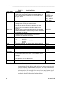
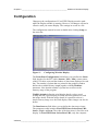
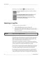
1
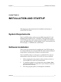
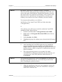
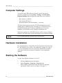
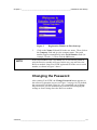
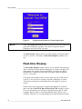
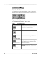
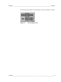
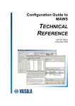
Real-time Display Software
YourVIEW 2000
YVU2000
USER'S GUIDE
M210681EN-B
August 2008
PUBLISHED BY
Vaisala Oyj
P.O. Box 26
FIN-00421 Helsinki
Finland
Phone (int.): +358 9 8949 1
Fax:
+358 9 8949 2227
Visit our Internet pages at http://www.vaisala.com/
© Vaisala 2008
No part of this manual may be reproduced in any form or by any means,
electronic or mechanical (including photocopying), nor may its contents be
communicated to a third party without prior written permission of the copyright
holder.
The contents are subject to change without prior notice.
Please observe that this manual does not create any legally binding obligations for
Vaisala towards the customer or end user. All legally binding commitments and
agreements are included exclusively in the applicable supply contract or
Conditions of Sale.
________________________________________________________________________________
Table of Contents
CHAPTER 1
GENERAL INFORMATION............................................................................ 3
About This Manual ................................................................... 3
Contents of This Manual ....................................................... 3
Version Information ............................................................... 4
Feedback............................................................................... 4
Safety......................................................................................... 4
General Safety Considerations ............................................. 4
Trademarks ............................................................................... 5
License Agreement .................................................................. 5
Technical Support .................................................................... 5
CHAPTER 2
PRODUCT OVERVIEW.................................................................................. 7
Overview of the System........................................................... 7
CHAPTER 3
INSTALLATION AND STARTUP................................................................... 9
System Requirements.............................................................. 9
Software Installation ................................................................ 9
Computer Settings ................................................................. 12
Hardware Installation ............................................................. 12
Starting the Software ............................................................. 12
Changing the Password ...................................................... 13
Real-time Display ................................................................ 14
CHAPTER 4
RECEIVER.................................................................................................... 17
Changing the Configuration.................................................. 18
Message Formats ................................................................... 19
Polling Rules........................................................................... 19
Receiving Rules...................................................................... 19
Control Buttons ...................................................................... 21
Load Button ......................................................................... 21
Save Button......................................................................... 21
Stop Button.......................................................................... 21
CHAPTER 5
DATA LOGGING .......................................................................................... 23
Changing the Configuration.................................................. 24
VAISALA ________________________________________________________________________ 1
User's Guide ______________________________________________________________________
CHAPTER 6
WEATHER 2 REAL-TIME DISPLAY............................................................27
Configuration ..........................................................................29
CHAPTER 7
BROWSER....................................................................................................31
Opening a Log File .................................................................32
CHAPTER 8
YOURVIEW WEB SERVER .........................................................................37
Web Server Settings...............................................................38
Display Address .....................................................................39
2 ___________________________________________________________________ M210681EN-B
Chapter 1 ________________________________________________________ General Information
CHAPTER 1
GENERAL INFORMATION
This chapter provides general notes for the manual and the product.
About This Manual
This manual covers the YourVIEW YVU2000 displays. This manual
provides information for installing, operating, and maintaining
YourVIEW YVU2000.
Contents of This Manual
This manual consists of the following chapters:
- Chapter 1, General Information, provides general notes for the
manual and the product.
- Chapter 2, Product Overview, introduces YourVIEW YVU2000,
the graphical user interface software for Vaisala automatic data
collection systems.
- Chapter 3, Installation and Startup, provides instructions for
installation and startup of YourVIEW YVU2000.
- Chapter 4, Receiver, provides information about the Receiver
module that receives data from the AWS and transmits data to the
Data Socket database.
- Chapter 5, Data Logging, provides information on the Data
Logging module that reads data from the Data Socket database and
stores it into a spreadsheet file.
- Chapter 6, Weather 2 Real-time Display, describes the display
objects and features of Weather 2 Real-time Display.
VAISALA ________________________________________________________________________ 3
User's Guide ______________________________________________________________________
- Chapter 7, Browser, provides information on the Browser module
that shows the the stored files in graphical and table formats.
- Chapter 8, YourVIEW WEB server, provides information on the
YourVIEW WEB Server that makes the display image available
over Internet.
Version Information
Table 1
Manual Revisions
Manual Code
M210681EN-A
M210681EN-B
Description
This manual. First release.
Information on Microsoft Vista added.
Feedback
Vaisala Customer Documentation Team welcomes your comments
and suggestions on the quality and usefulness of this publication. If
you find errors or have other suggestions for improvement, please
indicate the chapter, section, and page number. You can send
comments to us by e-mail: [email protected]
Safety
General Safety Considerations
Throughout the manual, important safety considerations are
highlighted as follows:
CAUTION
Caution warns you of a potential hazard. If you do not read and
follow instructions carefully at this point, the product could be
damaged or important data could be lost.
NOTE
Note highlights important information on using the product.
4 ___________________________________________________________________ M210681EN-B
Chapter 1 ________________________________________________________ General Information
Trademarks
Microsoft®, Windows®, and Windows NT® are registered
trademarks of Microsoft Corporation in the United States and/or other
countries.
License Agreement
All rights to any software are held by Vaisala or third parties. The
customer is allowed to use the software only to the extent that is
provided by the applicable supply contract or Software License
Agreement.
Technical Support
For technical questions, contact the Vaisala technical support:
E-mail
[email protected]
Phone (int.)
+358 9 8949 2789
Fax
+358 9 8949 2790
VAISALA ________________________________________________________________________ 5
User's Guide ______________________________________________________________________
This page intentionally left blank.
6 ___________________________________________________________________ M210681EN-B
Chapter 2 __________________________________________________________ Product Overview
CHAPTER 2
PRODUCT OVERVIEW
This chapter introduces YourVIEW YVU2000, the graphical user
interface software for Vaisala automatic data collection systems.
Overview of the System
The software is to be installed on a PC with operating system
Microsoft Windows 2000 , Windows XP, or Windows Vista.
YourVIEW YUV2000 offers a graphical presentation of real-time and
logged data and allows you to log data into your PC's hard disk.
Several modified displays are available.
YourVIEW consists of four modules that run simultaneously on your
PC:
- In the Receiver module, you define the communication settings for
receiving data from a data collecting system via your PC's serial
ports.
- The Data Logging module defines the data logging details.
- The Weather Display modules are used for real-time monitoring of
measured and calculated data.
- The Browser module allows you to study the logged history data in
more detail, both graphically and in table format.
Communication between the different modules is done by using the
Data Socket communication protocol (DSTP), which makes it
possible to have the Receiver, Display and Logging modules running
simultaneously in different computers connected to the same network
and using the same data. The Data Socket data packet also includes
the time stamp for each data packet.
VAISALA ________________________________________________________________________ 7
User's Guide ______________________________________________________________________
The YourVIEW operation is password-protected, preventing
unauthorized personnel from making changes to the settings or from
closing down the program. The password is needed to stop the
modules or to change the parameter settings.
8 ___________________________________________________________________ M210681EN-B
Chapter 3 ______________________________________________________ Installation and Startup
CHAPTER 3
INSTALLATION AND STARTUP
This chapter provides instructions for installation and startup of
YourVIEW YVU2000.
System Requirements
The YourVIEW software will run on any IBM compatible PC with
Windows 2000, Windows XP, or Windows Vista operating system.
YourVIEW typically requires approximately 20 MB of free hard disk
space and additional space for data logging. The PC must also have an
SVGA display, a CD-ROM drive, and a mouse.
Software Installation
These are the key instructions for installing the YourVIEW software.
It is assumed that the user of YourVIEW has a basic understanding of
using software running on the Windows operating system.
The YourVIEW software is delivered on a CD-ROM. The software
automatically selects the current VGA or SVGA screen resolution.
1.
Before starting the setup program, make sure that you have at
least 20 MB of free space on your hard disk.
2.
To install the software on your hard disk, choose Start - Run
and enter D:\SETUP.exe (where D: is your CD drive's letter) in
the YourVIEW directory.
3.
The Setup program guides you through the installation.
VAISALA ________________________________________________________________________ 9
User's Guide ______________________________________________________________________
0412-103
Figure 1
4.
YourVIEW Installation
When the Setup program asks for the installation directory, you
can accept the default by clicking the Finish button. In case you
want to change the default directory, click the Change button
and type the new path. It is recommended to install the software
in its own directory.
10 __________________________________________________________________ M210681EN-B
Chapter 3 ______________________________________________________ Installation and Startup
NOTE
By default, YourVIEW is installed in folder C:\Program
Files\YourVIEW. When started after installation, YourVIEW will
write to this path. With Windows XP and older Windows versions,
this will not pose any problems, but Windows Vista, which is strict
about file access, especially in C:\Program Files, and only gives
ordinary users read access to files by default, will cause trouble.
To circumvent this problem, so as follows:
On Windows Vista, install YourVIEW in a folder other than
C:\Program Files,
or
Give ordinary users full access to the files within the YourVIEW
installation folder. Do as follows:
NOTE
1.
Install YourVIEW under C:\Program Files\YourVIEW.
2.
Right click on C:\Program Files\YourVIEW, then click on
Properties.
3.
Select Security, then Edit.
4.
Highlight the group for ordinary users, then tick the full control
box.
5.
After installing the YourVIEW application, the installation
program automatically also installs the LabVIEW Runtime
Engine, which is required for running the application, as well as
the Data Socket, which is required for communication between
different modules.
6.
The setup program generates an executable file called
YOURVIEW.exe and the associated files into the directory you
selected for the YourVIEW path (the default directory is
YourVIEW).
The installation program also creates an Uninstall icon intended for
deleting YourVIEW from the PC, or for removing an old version
before installing the updated software.
7.
When the installation of the basic set is complete, remove the
CD-ROM from the drive. Store the CD-ROM in a safe place,
and/or take a backup copy.
VAISALA _______________________________________________________________________ 11
User's Guide ______________________________________________________________________
Computer Settings
To run the YourVIEW software properly, specify the general
Windows settings by selecting Start - Settings - Control Panel Regional Settings and check that the items below are as follows:
- Date format: yy-MM-dd
- Time format: HH:mm:ss
- Decimal delimiter (decimal symbol): . (a period)
The Data Socket protocol uses the TCP/IP data transfer protocol,
which must be installed as well. Normally, the TCP/IP protocol is
installed during the basic Windows installation, but if it is not
installed, you will find it on the Windows Installation CD.
With these settings, the LabVIEW function, which converts String to
Number, will work properly when parsing the received data messages.
NOTE
It is recommended that you do not use a screen saver.
Hardware Installation
For communications, YourVIEW uses the standard serial ports of the
PC. The default port is COM1. The default line settings are: 9600, 8,
1, N. For instructions on how to connect the maintenance terminal
cable between the device and your computer, see the applicable
manuals.
Starting the Software
To start YourVIEW in Windows 95 or NT:
1.
Click the Start button on the taskbar.
2.
Select Programs - Yourview - Yourview.exe.
When starting YourVIEW for the first time, the software
registration window opens, see Figure 2 on page 13.
12 __________________________________________________________________ M210681EN-B
Chapter 3 ______________________________________________________ Installation and Startup
0010-082
Figure 2
3.
NOTE
Registration Window at First Start-up
Click on the Name field and fill in the user name. Then click on
the Company field and give the company name. The serial
number appears automatically in the Serial Number field (for
example, Weather 1). Then click the OK button.
If the serial number field is left blank or it is not correctly filled in,
only the Receiver module will start. In this case, stop and close the
Receiver module. Start YourVIEW again and fill in the correct serial
number, as shown in Figure 2 above.
Changing the Password
After starting YourVIEW, the Change Password button appears on
the software registration screen (see Figure 3 on page 14). By default,
the password is left blank. However, we recommend you to change
the password to prevent unauthorized personnel from changing the
settings or from closing down the Receiver module.
VAISALA _______________________________________________________________________ 13
User's Guide ______________________________________________________________________
0010-083
Figure 3
NOTE
Registration Window at Normal Operation
Once the Change Password button has appeared, you can change the
password within three seconds. After three seconds the button
disappears and YourVIEW will start.
The Data Socket window and 3 to 6 other windows will open on the
screen of your PC. Normally, the Real-time Display window is on
top.
Real-time Display
The Real-time Display window allows you to monitor the measured
and/or calculated values that the datalogger or sensor is sending. The
data update rate depends on the application. Typically, the data is
updated once a minute except for the wind data, which is updated
every 1–2 seconds.
If the data is not updated on the screen, make sure the COM port of
your PC is free to receive messages from the datalogger or sensor.
Also make sure that the command mode to the logger or sensor is
closed.
If data comes from some other computer through the PC network,
make sure the YourVIEW Data Socket Root URL setting is correct.
For more information, see section Configuration on page 29. If the
computer name is used, it is possible that the name service is not
available. Therefore, it is recommended to use the IP address instead
14 __________________________________________________________________ M210681EN-B
Chapter 3 ______________________________________________________ Installation and Startup
of the PC name. The problem can also be caused by limited
communication rights in the PC network.
If a sensor is not connected or if data is unavailable, the data
collection device may send (depending on its configuration) any nonnumeric value between the delimiters, for example, ///// or nothing at
all (which would be received as two consecutive delimiters). In these
cases, the numeric displays will change to NaN (Not a Number) and
there will be gaps in the corresponding graph.
In Browser, the corresponding table cell contains the same string
value that was received in the message, for example, ///// or nothing at
all. An example of the Weather Display is shown in Figure 4 below.
0412-102
Figure 4
Weather 2 Display
Other windows can be opened by selecting the module name from the
Windows menu as shown in Figure 5 below. Alternatively, you can
click the Window button on the taskbar.
0105-143
Figure 5
Window Menu
VAISALA _______________________________________________________________________ 15
User's Guide ______________________________________________________________________
The Receiver and Real-time Display modules start running
automatically. In case this does not happen, start the modules by
clicking the
button at the top left corner of the display.
NOTE
Data will not be logged on your PC by default. For further details, see
Chapter 4, Receiver, on page 17.
In all program modules, you can also print the layout of the module by
choosing the Print Window command from the File menu or by
pressing CTRL+P.
A context-sensitive online help function is available in the YourVIEW
modules. You can activate the online help by selecting Show Help on
the Help menu. As you move the cursor on the screen, the Help
window displays information on the display items.
See the following chapters for more info on the Receiver, Data
Logging, Display and Browser modules.
16 __________________________________________________________________ M210681EN-B
Chapter 4 _________________________________________________________________ Receiver
CHAPTER 4
RECEIVER
This chapter provides information about the Receiver module that
receives data from the AWS and transmits data to the Data Socket
database.
This program module receives data from the AWS and transmits the
data to the Data Socket database for the real-time Display modules
and Data Logging module. YourVIEW Receiver starts automatically
at each start-up. In case it has been stopped, restart the program by
clicking Operate - Run on the menu bar.
0412-104
Figure 6
Receiver Window
VAISALA _______________________________________________________________________ 17
User's Guide ______________________________________________________________________
The Receiver module must be running continuosly to enable updating
of data from the data collection system to the Data Socket database.
Changing the Configuration
Changes in the configuration of YourVIEW Receiver must be made
while the Receiver is running. However, the changes will not be
effective until you restart the Receiver.
To edit the Receiver settings, click on the field to be edited. When you
have modified a field, confirm the change by pressing ENTER. The
modification(s) will be ignored until you have pressed ENTER.
When you start the YourVIEW software for the first time, we
recommend that you go through the following checklist (especially if
you want to change the default settings). After that, you should stop
the Receiver by clicking the Stop button, especially if you have made
any changes to the default settings.
1.
Check the communication port parameters. Make sure that the
communications parameters set for the data collection system
also correspond to those set in YourVIEW Receiver. The default
parameters are: 9600, 8, 1, N.
2.
Check the start and end characters.
3.
Set the timeout interval to be slightly longer than the data
message transmission interval in the datalogger or sensor.
4.
Check the Data Socket and Clock parameters. By default,
internal PC clock is used.
The settings for the Receiver module are saved in a file called
receiver.cfg.
NOTE
The old file is overwritten when changes are saved. Therefore, make
a copy of the original file for backup purposes.
18 __________________________________________________________________ M210681EN-B
Chapter 4 _________________________________________________________________ Receiver
Message Formats
This section explains the message formats that YourVIEW uses. You
can configure the messages to suit your application, sensor set and
display/data logging requirements.
Each real-time display must have specific message definitions but
there can also be additional messages only for datalogging.
Polling Rules
The Your VIEW program can be set to poll the data collection device
for the data instead of automatically receiving it.
Polling rules define the polling string transmitted to the data collection
device by YourVIEW. Transmission interval as well as the reply
waiting time must be defined. Both times are given in seconds with a
resolution of 0.1 seconds.
Receiving Rules
There can be several rules for incoming data messages from the data
collection equipment. Receiver can receive several types of data
messages at different intervals. By changing the Receive Rule
number, you can define multiple report definitions coming in on a
single serial port.
NOTE
When you have installed Real-time Display, the default settings
already include the required receiving rules. There is no need to
change the settings.
VAISALA _______________________________________________________________________ 19
User's Guide ______________________________________________________________________
Table 2
Receiving Rules
Field name
Type
Description
Defines the message output format. This information will be
used by other parts of the program to parse and display the
data. If you are using a format that you cannot find in the
list, type "Other".
Length
Timeout, sec
The maximum length of a received data message.
The maximum time Receiver waits for the end of a data
message after receiving the start characters.
Note that the timeout interval must be longer than the
interval between consecutive messages! When timeout is
detected, the numeric field is changed to NaN (= not a
number).
The first characters that must be received by the computer
to determine the start of a new message. Control characters
are defined in hex format.
The end characters in the received message that tell the
computer that the current message is over. Control
characters are defined in hex format.
\01
is <SOH>
\02
is <STX>
\03
is <ETX>
AA
is <ID><Message Type>
\r
is <CR>
\n
is <LF>
If the path is defined, the message body will be written into
text file : <path>\topic.txt
Optional acknowledgement string
Optional negative acknowledgement string
Topic name for Data Socket
Optional list for E-mail recipients of data messages
Start chars
End chars
Path
Ack
Nack
Topic
E-mail
Recipients
Item name
Unit
Min
Max
Description
Default
|xx.x|xx.x|xx.x|
(| = any
delimiter), Plain
Text, WAT11,
DDP25, CT25K
Msg1, PWD11
Msg2, Other.
200 characters
125 seconds
\01PTU\02
\03\r\n
Empty
Empty
Empty
Empty
Empty
Defines the order and name of the variables received. Use
the scroll bars to add more names. The number of rows in
the table should be the same as values in the incoming
message.
Defines the units of the variables received. The units will
also appear on the Log data header.
Optional minimum value for data.
Optional maximum value for data.
Optional description for data item.
Items are specified in the item table giving the sensor's name, its unit,
optional min/max limitation and description. The order of the sensors
in this list should be the same as in the incoming serial message. Any
unit conversion (for example, from m/s to knots) must be made in the
data collection equipment. The names and units defined here will be
used as the header information for logged data.
20 __________________________________________________________________ M210681EN-B
Chapter 4 _________________________________________________________________ Receiver
Control Buttons
The three main control buttons are Load, Save and Stop.
Load Button
When loading new receiving rules for Your VIEW or a new
configuration to Receiver, click the Load button. The file type is cfg.
Loading a new configuration is a password-protected operation. Type
in the password and click OK. Then select the *.cfg file. Restart
YourVIEW by clicking the
button at the top left corner.
Save Button
When creating a new receiving rule or modifying an existing one,
click the Save button. The current configuration of Receiver will be
saved to the Receiver.cfg file. This is a password-protected operation.
Type in the password and then click OK.
NOTE
The old file is overwritten when changes are saved. Therefore, make
a backup copy of the original file.
Stop Button
The Stop button stops the Receiver module from running and
receiving any information. The changes made in the settings will only
take effect after you stop running Receiver and then restart the
program. This is normally a password-protected operation. Therefore,
type in the password, as shown in Figure 7 on page 22, and then click
OK.
VAISALA _______________________________________________________________________ 21
User's Guide ______________________________________________________________________
0105-147
Figure 7
Enter Password Dialog
If no password has been set, you just need to click OK in the Enter
Password? dialog.
22 __________________________________________________________________ M210681EN-B
Chapter 5 _____________________________________________________________ Data Logging
CHAPTER 5
DATA LOGGING
This chapter provides information on the Data Logging module that
reads data from the Data Socket database and stores it into a
spreadsheet file.
The Data Logging module module takes care of data logging. This
module reads data from the Data Socket database and stores it into a
spreadsheet file. File names are created according to the date and time,
for example, 96110600.CSV. The files are synchronized to midnight.
Data will be logged in comma separated ASCII format and it can also
be read directly, for example, into MS Excel. The module supports
several different datalogging profiles simultaneously.
0412-105
Figure 8
Data Logging Window
VAISALA _______________________________________________________________________ 23
User's Guide ______________________________________________________________________
The Data Logging module must be running continuosly to enable
updating of data from the data collection system to the data storage on
the hard disk.
The Data Logging module stores data only if the data is changed. By
default, there is no minimum limit for data change, but it is possible to
define a minimum change with the Deadband parameter. All data in
each log definition is stored if any of the items change.
The Data Logging module also supports FTP and E-mail data transfer.
However, these features are optional and require installation-specific
settings in the YourVIEW initialization files before they can be used.
Changing the Configuration
The settings for the Data Logging module are saved in a file called
logger.cfg.
NOTE
The old file is overwritten when changes are saved. Therefore, make
a backup copy of the original file.
Changes in the configuration of YourVIEW Data Logging must be
made while the Receiver is running. However, the changes will not be
effective until you restart the module.
24 __________________________________________________________________ M210681EN-B
Chapter 5 _____________________________________________________________ Data Logging
Table 3
Field Name
Log File Path
Duration
Autodel
Min Intvl
Log Items
Data Logging Rules
Description
Defines the directory in which the logged data folders and/or files are located.
The default logfile path is C:\YOURVIEW. If <logfile path> is empty, log files will
be stored in the LabVIEW default directory.
Defines when a new log file will be created, based on time. The length of the
logged file can be set in this field. The default value is 24 hours. For example,
setting 1 creates a new file every hour.
NOTE: If the logging interval is set very short (for example, 1 min.), it is
recommended to set the file duration short as well (for example, 1 hour, or 1 day
at maximum).
Defines files older than the specified value (in hours) to be deleted
automatically. If autodel is set to zero (0) there is no auto deleting. The default
values is 0. When autodel is set = 0, the user must monitor the availability of
hard disk space for log files.
Defines the minimum interval for data logging. If Min Intvl is set to 1 minute, data
is not logged more often than once a minute even if the data value is updated
more often.
Define the data items to be logged.
YourVIEW Data
Socket Root URL
Only the computer identification can be changed here. By default, the
identification is Localhost, which means the computer itself. Optionally, the
identification can be the name or TCP/IP address of the computer that produces
the data.
Source
Source name for the data. This must match with the receiver settings.
Topic
Topic name for the data. This must match with the receiver settings.
Name
Item name for the data. This must match with the receiver settings.
Deadband
Minimum required change of data value before it is logged. The default is
empty, meaning that all changes are logged. If one of the defined items
changes, all values will be logged.
FTP Recipients
Optional FTP configuration
Email Attachments Optional E-mail configuration
Data will be logged as Comma Separated Values (CSV) ASCII
characters. The files can be read directly by other application
software, such as MS Excel. The header of each file specifies the
names and units of all the parameters in the file. Opening a log file
into MS Excel, each value is inserted in its own cell.
VAISALA _______________________________________________________________________ 25
User's Guide ______________________________________________________________________
This page intentionally left blank.
26 __________________________________________________________________ M210681EN-B
Chapter 6 _________________________________________________ Weather 2 Real-time Display
CHAPTER 6
WEATHER 2 REAL-TIME DISPLAY
This chapter describes the display objects and features of Weather 2
Real-time Display.
0412-102
Figure 9
Weather 2 Real-time Display
Start the program module by clicking the
corner of the display.
button at the top left
The display is a real-time data display with graphs, numeric data
boxes, wind display with selectable data averaging periods and with
minimum and maximum values. The wind display also includes a very
intuitive presentation on the variation in the wind direction during
selected periods.
VAISALA _______________________________________________________________________ 27
User's Guide ______________________________________________________________________
The date and time on the Weather Display are the same as on your
computer.
The Display includes fields for air temperature, humidity, dew point
temperature, pressure, solar, precipitation sum, etc. The contents of
the data field depend on the configuration of the reports sent by
MAWS or MILOS520. The text field titles are editable.
A history window plots the previously received values for the selected
sensor. You can select the variable from the title list above the graph
area. The real-time graphs have a capacity of 360 values. The
PlotRate setting from 1 to 120 seconds extends these graphs from 6
minutes up to the last 12 hours.
The value (y) scale of the graphs is either auto-scaling or manual. To
change the value range manually, double-click or highlight the upper
or lower range with your mouse, type in the new limit, and press
ENTER. Manual scaling can be switched off by clicking the righthand button of the mouse and selecting Auto-scaling on (9).
The Wind Avg field allows you to define the wind direction interval
and the average wind speed. The averages can be set at intervals of 2
minutes, 10 minutes, or alternatively, you can select instant values (at
an average of 6 seconds). The Wind display shows average numeric
values at the selected intervals at the top right corner of the display.
The Wind display shows average wind direction values during a
selected period in orange color and variations in wind direction during
a selected period in yellow.
The Wind Avg field and the Wind display are shown in Figure 10
below.
0412-106
Figure 10
Wind Avg Field and Wind Display
28 __________________________________________________________________ M210681EN-B
Chapter 6 _________________________________________________ Weather 2 Real-time Display
Configuration
Changes to the configuration of YourVIEW Display must be made
while the Display module is running. However, all changes will not be
effective until you restart Display. The settings are saved in a file.
The configuration controls become available after clicking Setup on
the menu bar.
0412-107
Figure 11
Configuring Weather Display
The Front Panel Configuration field allows you to define the Name
field, headers for the PTU table (Instant / Max / Min), sensor names
of the PTU table, units and the number of data-items displayed in each
line. The number of points that are printed in the graphics window
defines the available history length together with the PlotRate
parameter. Note that the number of points has an effect on the
memory usage of the program.
WAD21 defaults define the wind display details, colors, speed
scaling and unit, speed display precision, direction pointer size, and
the image details. With the image details it is possible to draw a
simple runway image over the wind display. Other images can also be
drawn.
The Data Sources field allows you to define the data source items.
The parameters table includes YourVIEW Data Socket Root URL,
Source, Topic, and Item. The order of the data items is fixed for each
display. In YourVIEW Data Socket Root URL, only the computer
VAISALA _______________________________________________________________________ 29
User's Guide ______________________________________________________________________
identification can be changed. By default, the identification is
Localhost, which means the computer itself. Optionally, the
identification can be the name or TCP/IP address of the computer that
produces the data. Source, Topic and Name define the data item and
must match with the receiver settings. In Weather 2 display the first
three data items are for wind display and rest are for data table.
30 __________________________________________________________________ M210681EN-B
Chapter 7 _________________________________________________________________ Browser
CHAPTER 7
BROWSER
This chapter provides information on the Browser module that shows
the the stored files in graphical and table formats.
Browser is used for browsing the stored files in graphical and table
formats. In Figure 12 below, the parameter TA1 has been selected
from the parameter list and is displayed in the graph and table.
9909-041
Figure 12
NOTE
Browser Window
Weather Display does not store files on your PC by default. See
Chapter 5, Data Logging on page 23 for details on how to activate
logging.
VAISALA _______________________________________________________________________ 31
User's Guide ______________________________________________________________________
Start Browser by clicking the
button at the top left corner.
Clicking the New File button opens a new file for viewing in
Browser.
Clicking the Print Graph button prints the graph using the
current Windows printing defaults. The printout is
automatically designed to fill an entire A4-size page.
Clicking the Print Table button prints the table using the
current Windows printing defaults.
Opening a Log File
To open a log file, proceed as follows:
NOTE
1.
Click the New File button to open a new log file.
2.
Select the directory and then the logged file you want to open.
The parameter list will be read automatically from the header of
the file to be opened.
3.
Select the data items to be displayed from the parameter list.
Data will not be logged by default.
Normally, only one data item type is selected at a time. If you want to
browse through several parameters simultaneously, hold down the
SHIFT key and select the required parameters with the mouse. The
scale is defined according to the largest parameter.
Each graph corresponding to a parameter is displayed in a different
color. You can change the color of any parameter. The numeric values
of these parameters are updated automatically in the table.
If a file has been opened and the program simultaneously stores data
into it, the curves and the chart will not be updated automatically. If
you want to update the data, reselect the file you are browsing.
By clicking the mouse between the parameters' box and the graph
color examples, the graph definition options are displayed. You can
change the graph color and pattern according to the available options.
32 __________________________________________________________________ M210681EN-B
Chapter 7 _________________________________________________________________ Browser
The graph controls are introduced in Table 4 below.
Table 4
Button
The Graph Controls
Description
The X-autoscale button is used for scaling the time of the
graph.
X-autoscale
The Y-autoscale button is used for scaling the Y-data of
the graph and for continuous autoscaling of either scale.
Y-autoscale
Right-clicking the X-scale format button will open the
Format, Precision, and Mapping Mode buttons.
The Format button is used to format the data on the XX-scale format axis. Valid choices are Decimal, Scientific, Engineering,
Binary, Octal, Hexadecimal, Relative Time, and Absolute
Time.
The Precision button is used to format the data on the Xaxis with the precision selected. Valid choices are 0, 1, 2,
3, 4, 5, and 6.
With Mapping Mode, the valid choices are linear and
logarithmic.
Clicking the Y-scale format button will open the actual
format buttons Format, Precision, and Mapping Mode.
They are used as X-scale format buttons apart from the
Y-scale format last three buttons, which control the operation mode for the
graph.
buttons
Right-clicking the Zoom button will open the zooming tools.
See Table 5 on page 34 for details.
Zoom
With the Panning tool you can scroll visible data by
clicking and dragging the sections of the graph.
Pan
Cursor
The Cursor can be moved to the left or right, and with the
Lock button also along the interpolated values. When two
or several graphs are displayed simultaneously, the cursor
can be moved from one graph to another (Up and Down
buttons). The locations show the numeric values of the
cursor location shown in Figure 13 on page 34.
VAISALA _______________________________________________________________________ 33
User's Guide ______________________________________________________________________
0105-149
Figure 13
The Cursor
The cursor appears on the display as shown in Figure 13 above and
the graph controls appear on the display as shown in Figure 14 below.
0105-148
Figure 14
The Graph Controls
The zooming tools are explained in Table 5 below.
Table 5
The Zooming Tools
Button
Description
With the Zoom In tool, you can zoom in on a
section of the graph by dragging the selection
rectangle around the desired section.
Zoom In
This is the Undo Zoom button.
Undo Zoom
This is the Time-restricted Zooming button.
The Y-axis remains unchanged.
Time-restricted Zooming
Continuous Zooming In
When you click the Continuous Zooming In
button and hold down the mouse on a specific
point, the graph zooms in continuously until you
release the mouse button.
The Y-data-restricted Zooming tool is
restricted to zooming Y-data. The time remains
unchanged.
Y-data-restricted
Zooming
34 __________________________________________________________________ M210681EN-B
Chapter 7 _________________________________________________________________ Browser
The zooming tools appear on the display as shown in Figure 15 below.
0105-150
Figure 15
The Zooming Tools
VAISALA _______________________________________________________________________ 35
User's Guide ______________________________________________________________________
This page intentionally left blank.
36 __________________________________________________________________ M210681EN-B
Chapter 8 ______________________________________________________YourVIEW WEB server
CHAPTER 8
YOURVIEW WEB SERVER
This chapter provides information on the YourVIEW WEB Server
that makes the display image available over Internet.
YourVIEW 2000 runs its own web server, which launches the display
image available over Intranet. Displays are launched as .jpg images
that are not updated automatically. The display can be updated by
clicking the Refresh button of the web browser.
0412-108
Figure 16
Web Display
VAISALA _______________________________________________________________________ 37
User's Guide ______________________________________________________________________
Web Server Settings
NOTE
Web Server is not be available by default.
Web Server should be enabled after installation. By default, it is
disabled.
To enable the web server, follow the instructions below:
1.
Select the YourVIEW Receiver window.
2.
Select from the menu bar Tools - Options - Web Server:
Configuration.
3.
Select Enable Web Server. Use the default Root Directory and
default HTTP Port, see Figure 17 below.
0412-109
Figure 17
Web Server Configuration
38 __________________________________________________________________ M210681EN-B
Chapter 8 ______________________________________________________YourVIEW WEB server
Display Address
The display address is, for example, the following:
http://localhost/.snap?YourVIEW+Weather+2+Display.vi
Where localhost means the computer itself and should be replaced by
the TCP-IP address or name of the computer where the YourVIEW
2000 application is running. If there are other displays available in
addition to Weather 2 Display, they can be accessed by typing the
name of the display module into the address field.
If your web browser cannot find the page and you get the response
shown in Figure 18 below, make sure the YourVIEW 2000
application is currently running and the address is correctly typed.
0412-110
Figure 18
Web Page Not Found
VAISALA _______________________________________________________________________ 39