1
SPRZ113A
Manual Update Sheet
DATE: June 1, 1998
Document Being Updated: TMS320C5x User’s Guide
Literature Number Being Updated: SPRU056C
Manual Included in a Kit: Yes
This Manual Update Sheet (SPRZ113A) ships with the TMS320C5x User’s Guide.
Updates within paragraphs appear in a bold typeface.
Page:
Change or Add:
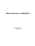
3–3
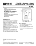
In the bottom half of Figure 3–1, the auxiliary register file MUX output now connects with the
trailing wire bus found on the data bus.
Figure 3–1. Block Diagram of ’C5x DSP – Central Processing Unit (CPU)
DATA BUS
7 LSB
from IREG
3
†
AR0
AR1
ST0 [ARP]
DBMR
Buffered
Serial
Port
MUX
Timer
ST0 [DP]
AR2
MUX
AR3
AR4
3
3
9
AR5
AR6
TREG0
AR7
MULTIPLIER
CBCR(8)
PRESCALER
SFL(0–16)
CBER1
PLU
P–SCALER
(–6,0,1,4)
MUX
32
INDX
32
ARCR
I/O Ports
Host Port
Interface
32
CBER2
MUX
†
PREG(32)
DRB
CBSR1
CBSR2
32
PRESCALER
SFR(0–16)
PA0
Emulation
MUX
ARAU
32
MUX
PA15
ALU(32)
32
32
Data/Program
MUX
MUX
Data/Program
DARAM
B0
Data
DARAM
B2
ACCH
32
ACCL
ACCB(32)
32
B1
MUX
POSTSCALER
(0–7)
MUX
Notes: All registers and data lines are 16-bits wide unless otherwise specified.
† Not available on all devices.
1
PROGRAM BUS
SARAM
ST1 [C]
DATA BUS
Page:
Change or Add:
4–11
In Table 4–5, change the reset values for the ARP bit and the OVM bit so both have a reset
value of “X.” In other words, there is no reset value for the ARP bit and the OVM bit.
Table 4–5.
Bit
Name
Status Register 0 (ST0) Bit Summary
Reset
value
Function
15–13
ARP
X
Auxiliary register pointer. These bits select the auxiliary register (AR) to be used in
indirect addressing. When the ARP is loaded, the previous ARP value is copied to
the auxiliary register buffer (ARB) in ST1. The ARP can be modified by memory-reference instructions when you use indirect addressing, and by the MAR or LST #0
instruction. When an LST #1 instruction is executed, the ARP is loaded with the same
value as the ARB.
11
OVM
X
Overflow mode bit. This bit enables/disables the accumulator overflow saturation
mode in the arithmetic logic unit (ALU). The OVM bit can be modified by the LST #0
instruction.
4–12
OVM = 0
Disabled. An overflowed result is loaded into the accumulator without
modification. The OVM bit can be cleared by the CLRC OVM instruction.
OVM = 1
Overflow saturation mode. An overflowed result is loaded into the accumulator with either the most positive (00 7FFF FFFFh) or the most
negative value (FF 8000 0000h). The OVM bit can be set by the
SETC OVM instruction.
In Table 4–5, change the reset value for the DP bit so it has a reset value of “X.” In other words,
there is no reset value for the DP bit.
Table 4–5.
Bit
Name
8–0
DP
Status Register 0 (ST0) Bit Summary (Continued)
Reset
value
X
Function
Data memory page pointer bits. These bits specify the address of the current data
memory page. The DP bits are concatenated with the 7 LSBs of an instruction word
to form a direct memory address of 16 bits. The DP bits can be modified by the
LST #0 or LDP instruction.
2
Page:
Change or Add:
4–13
In Table 4–6, change the reset value for the ARB bit and the TC bit so they have no reset
value.
Table 4–6. Status Register 1 (ST1) Bit Summary
Bit
15–13
11
Name
Reset
value
Function
ARB
X
Auxiliary register buffer. This 3-bit field holds the previous value contained in the
auxiliary register pointer (ARP) in ST0. Whenever the ARP is loaded, the previous
ARP value is copied to the ARB, except when using the LST #0 instruction. When
the ARB is loaded using the LST #1 instruction, the same value is also copied to
the ARP. This is useful when restoring context (when not using the automatic context save) in a subroutine that modifies the current ARP.
TC
X
Test/control flag bit. This 1-bit flag stores the results of the arithmetic logic unit (ALU)
or parallel logic unit (PLU) test bit operations. The TC bit is affected by the APL, BIT,
BITT, CMPR, CPL, NORM, OPL, and XPL instructions. The status of the TC bit determines if the conditional branch, call, and return instructions execute. The TC bit
can be modified by the LST #1 instruction.
3
Page:
Change or Add:
5–2
In Figure 5–1, change the page 0 length to “128-WORD PAGE.”
Figure 5–1. Direct Addressing
ST0
DP (9)
IREG (16)
7 LSBs
9
15
6
DP
0
16-bit data memory address
dma
PAGE 511
PAGE 510
512 DATA
PAGES
PAGE 3
PAGE 2
PAGE 1
PAGE 0
128-WORD
PAGE
(MEMORYMAPPED
REGISTERS
AND
DARAM B2)
4
DAB
Page:
Change or Add:
5–22
In Example 5–13, add two new lines at the beginning of the example.
Example 5–13. Circular Addressing
mar
ldp
*,ar6
#,0
splk
splk
splk
#200h,CBSR1
#203h,CBER1
#0Eh,CBCR
;
;
;
Circular buffer start register
Circular buffer end register
Enable AR6 pointing to buffer 1
lar
lacc
ar6,#200h
*
;
;
Case 1
AR6 = 200h
lar
lacc
ar6,#203h
*
;
;
Case 2
AR6 = 203h
lar
lacc
ar6,#200h
*+
;
;
Case 3
AR6 = 201h
lar
lacc
ar6,#203h
*+
;
;
Case 4
AR6 = 200h
lar
lacc
ar6,#200h
*–
;
;
Case 5
AR6 = 1FFh
lar
lacc
ar6,#203h
*–
;
;
Case 6
AR6 = 200h
lar
adrk
ar6,#202h
2
;
;
Case 7
AR6 = 204h
lar
adrk
ar6,#203h
2
;
;
Case 8
AR6 = 200h
5
Page:
Change or Add:
6–32
Change the second operand for the ADD instruction.
0 ≤ shift ≤16 (defaults to 0)
Operands
6–44
Change the fourth operand for the AND instruction.
0 ≤ shift ≤ 16
Operands
6–83
Change the operand for the BSAR instruction.
1 ≤ shift ≤ 16
Operands
6–85
Change the description for the CALAD instruction.
Description
The current program counter (PC) is incremented by 3 and pushed onto
the top of the stack (TOS).
Then, the one 2-word instruction or two 1-word instructions following the
CALAD instruction are fetched from program memory and executed before the
call is executed.
Then, the contents of the accumulator low byte (ACCL) are loaded into the PC.
Execution continues at this address.
The CALAD instruction is used to perform computed subroutine calls. CALAD
is a branch and call instruction (see Table 6–8).
6–87
Change the description for the CALLD instruction.
Description
The current program counter (PC) is incremented by 4 and pushed onto
the top of the stack (TOS).
Then, the one 2-word instruction or two 1-word instructions following the
CALLD instruction are fetched from program memory and executed before the
call is executed.
The program memory address (pma) is loaded into the PC. Execution continues at this address. The current auxiliary register (AR) and auxiliary register
pointer (ARP) are modified as specified. The pma can be either a symbolic or
numeric address.
CALLD is a branch and call instruction (see Table 6–8).
6
Page:
Change or Add:
6–91
Change the description for the CCD instruction.
Description
If the specified conditions are met, the current program counter (PC) is
incremented by 4 and pushed onto the top of the stack (TOS).
Then, the one 2-word instruction or two 1-word instructions following the CCD
instruction are fetched from program memory and executed before the call is
executed.
Then, the program memory address (pma) is loaded into the PC. Execution
continues at this address. The pma can be either a symbolic or numeric address. Not all combinations of the conditions are meaningful. In addition, the
NTC, TC, and BIO conditions are mutually exclusive.
If the specified conditions are not met, control is passed to the next instruction.
The CCD functions in the same manner as the CALLD instruction (page 6–87)
if all conditions are true. CCD is a branch and call instruction (see Table 6–8).
6–103
Opcode
6–115
Operands
6–127
Change the opcode for the CRLT instruction to reflect the new values for bits 2, 1, and 0.
15
1
14
0
13
1
12
1
11
1
10
1
9
1
8
0
7
0
6
0
5
0
4
1
3
1
2
1
1
0
0
0
Change the third operand for the LACC instruction.
0 ≤ shift ≤ 16 (defaults to 0)
Change the table Cycles for a Single Instruction (short immediate addressing).
Cycles for a Single Instruction (short immediate addressing)
Operand
6–129
ROM
DARAM
SARAM
External Memory
2
2
2
2+pcode
Change the table Cycles for a Single Instruction (short immediate addressing).
Cycles for a Single Instruction (short immediate addressing)
Operand
6–188
Operands
6–261
Operands
ROM
DARAM
SARAM
External Memory
2
2
2
2+pcode
Change the fourth operand for the OR instruction.
0 ≤ shift ≤ 16
Change the second operand for the SUB instruction.
0 ≤ shift ≤ 16 (defaults to 0)
6–278
Change the data memory address in Example 1 from 1905h to 1005h.
6–282
Change the fourth operand for the XOR instruction.
Operands
0 ≤ shift ≤ 16
7
Page:
Change or Add:
8–6
In Figure 8–6, change the word Off-chip to Reserved on the Program memory map for the
range from 0040h to 8000h.
8–11
In Table 8–6, change the values in the Off-Chip column for the first and fifth rows.
Table 8–6. ’C57S Program Memory Configuration
ÁÁÁÁÁÁÁÁÁÁ
ÁÁÁÁÁÁ
ÁÁÁÁÁ
ÁÁÁÁÁÁÁ
ÁÁÁÁÁÁ
ÁÁÁÁ
ÁÁÁÁ
ÁÁÁÁ
ÁÁÁÁÁÁ
ÁÁÁÁÁ
ÁÁÁÁÁÁÁ
ÁÁÁÁÁÁ
ÁÁÁÁÁÁÁÁÁÁ
ÁÁÁÁ
ÁÁÁÁ
ÁÁÁÁ
ÁÁÁÁÁÁ
ÁÁÁÁÁ
ÁÁÁÁÁÁÁ
ÁÁÁÁÁÁ
ÁÁÁÁ
ÁÁÁÁ
ÁÁÁÁ
ÁÁÁÁÁÁ
ÁÁÁÁÁ
ÁÁÁÁÁÁÁ
ÁÁÁÁÁÁ
ÁÁÁÁ
ÁÁÁÁ
ÁÁÁÁ
ÁÁÁÁÁÁ
ÁÁÁÁÁ
ÁÁÁÁÁÁÁ
ÁÁÁÁÁÁ
Bit values
CNF
RAM
MP/MC
ROM
(2K-words)
SARAM
(6K-words)
DARAM B0
(512-words)
Off-Chip
0
0
0
0000–07FF
Off-chip
Off-chip
8000–FFFF
1
0
0
0000–07FF
Off-chip
FE00–FFFF
8000–FDFF
8–32
Change the last sentence in the fourth bullet.
-
9–10
32K words of global data memory are enabled initially in data spaces
8000h to FFFFh. After the code transfer is complete, the global memory
is disabled before control is transferred to the destination address in program memory.
In Table 9–4, change the sentences after Soft=0 and Soft=1. Also, add a sentence to the TSS
register.
Table 9–4. Timer Control Register (TCR) Bit Summary
Bit
Name
11
Soft
4
9–11
TSS
Reset
value
0
0
Function
This bit is used in conjunction with the Free bit to determine the state of the timer
when a halt is encountered. When the Free bit is cleared, the Soft bit selects the
emulation mode.
Soft = 0
The timer stops immediately.
Soft = 1
The timer stops after decrementing to zero.
Timer stop status bit. This bit stops or starts the on-chip timer. At reset, the TSS
bit is cleared and the timer immediately starts timing. Note that due to timer logic
implementation, two successive writes of one to the TSS bit are required to
properly stop the timer.
Delete the last sentence in the Notes section and replace it with the sentence indicated.
The current value in the timer can be read by reading the TIM; the PSC can be read by reading the TCR.
Because it takes two instructions to read both registers, there may be a change between the two reads
as the counter decrements. Therefore, when making precise timing measurements, it may be more accurate to stop the timer to read these two values. Due to timer logic implementation, two instructions are also required to properly stop the timer; therefore, two successive writes of one to the
TSS bit should be made when the timer must be stopped.
8
Page:
Change or Add:
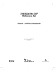
9–62
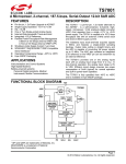
Change the XINT and RINT labels found in the lower right portion of Figure 9–35.
Figure 9–35. ABU Block Diagram
BCLKX
BDXR
SPCE
WXINT
BFSX
BDX
BXSR
BDR
BRSR
Serial Port
Control Logic
BXNT
Interrupt
Logic
Interrupt
Control
WRINT
BRNT
BCLKR
BFSR
BDRR
BSPC
Serial Port Interface Module
9
Page:
Change or Add:
9–63
Change the last sentence in the first paragraph.
The internal ’C5X memory used for autobuffering consists of a 2K-word block
of single-access memory that can be configured as data, program, or both (as
with other single-access memory blocks). This memory can also be used by
the CPU as general purpose storage, however, this is the only memory block
in which autobuffering can occur. Since the BSP is implemented on several different TMS320 devices, the actual base address of the ABU memory may not
be the same in all cases. The 2K-word block of BSP memory is located at
800h–FFFh in data memory or at 8000h–87FFh in program memory as
specified by the RAM and OVLY control bits.
10
Page:
Change or Add:
A–4
In Figure A–2, change the signal name on pin 80 to R/W.
*
DS
VSSC
*
PS
IS
*
BR
STRB
R/W
*
TDO
VDDC
X1
X2/CLKIN
*
CLKMD2
VSSI
VSSI
CLKOUT1
XF
HOLDA
VDDC
VDDI
VDDI
Figure A-2. Pin/Signal Assignments for the ’C51, ’C52, ’C53S, and ’LC56 in 100-Pin
TQFP
100 99 98 97 96 95 94 93 92 91 90 89 88 87 86 85 84 83 82 81 80 79 78 77 76
EMU0
EMU1/OFF
VSSC
TOUT
1
75
2
74
3
73
*
*
*
*
RS
READY
HOLD
BIO
TRST
VSSI
VSSI
MP/MC
D15
D14
D13
D12
5
4
72
71
(PZ package)
6
70
(Top view)
7
69
8
68
9
67
10
66
11
65
12
64
13
63
14
62
15
61
16
60
17
59
18
58
19
57
20
56
D11
D10
D9
D8
21
55
22
54
23
53
24
52
VDDD
25
51
Note:
*
*
*
*
*
VDDA
INT2
INT3
INT4
NMI
INT1
38 39 40 41 42 43 44 45 46 47 48 49 50
D7
D6
D5
D4
D3
D2
D1
D0
TMS
VDDD
TCK
VSSD
VSSD
VSSD
VSSD
26 27 28 29 30 31 32 33 34 35 36 37
WE
RD
VDDA
A15
A14
A13
A12
A11
A10
CLKMD1
VSSA
VSSA
TDI
VDDI
A9
A8
A7
A6
A5
A4
A3
A2
A1
A0
VSSA
These pins are reserved for specific devices (see Table A–6 on page A-12).
11
Page:
Change or Add:
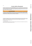
A–6
In Figure A–3, change the signal name on pin 108 to X2/CLKIN.
VSSC
DS
HD2
VSSC
PS
IS
R/W
STRB
BR
HD3
CLKMD3
X2/CLKIN
VDDC
X1
VSSI
TDO
FSX
HD5
CLKMD2
HD4
VSSI
HD7
BFSX
HD6
VDDI
CKLOUT1
XF
HOLDA
BDX
DX
VDDC
VDDI
Figure A–3. Pin/Signal Assignments for the ’LC57 in 128-Pin TQFP
128 127 126 125 124 123 122 121 120 119 118 117 116 115 114 113 112 111 110 109 108 107 106 105 104 103 102 101 100 99 98 97
HINT
EMU0
EMU1/OFF
VSSC
VSSC
TOUT
BCLKX
CLKX
VDDC
BFSR
BCLKR
RS
READY
HOLD
BIO
VDDC
VDDC
IAQ
TRST
VSSI
VSSI
1
96
2
95
94
3
4
(PBK package)
5
(Top view)
93
92
6
91
7
90
8
89
9
88
10
87
11
86
12
85
13
84
14
83
15
82
16
81
17
80
18
79
19
78
20
77
21
76
MP/MC
D15
D14
D13
22
23
75
24
73
25
72
D12
D11
26
71
27
70
D10
D9
D8
28
69
29
68
30
67
VDDD
VDDD
31
66
74
32
65
12
HAS
BDR
FSR
CLKR
VDDA
VDDA
NMI
DR
INT3
INT4
HBIL
INT2
HR/W
INT1
VSSD
VSSD
VDDD
TCK
HCNTL1
VDDD
VSSD
VSSD
D7
D6
D5
D4
D3
D2
D1
D0
HCNTL0
TMS
33 34 35 36 37 38 39 40 41 42 43 44 45 46 47 48 49 50 51 52 53 54 55 56 57 58 59 60 61 62 63 64
WE
HD1
RD
HD0
HRDY
VDDA
A15
A14
A13
A12
A11
A10
CLKMD1
VSSA
VSSA
TDI
HDS1
HDS2
VDDI
VDDI
A9
A8
A7
A6
A5
A4
A3
A2
A1
A0
VSSA
HCS
Page:
Change or Add:
A–7
In Table A–3, change the signal name on pin 108 to X2/CLKIN and reorder the signal names.
Table A–3. Signal/Pin Assignments for the ’LC57 in 128-Pin TQFP
Signal
Pin
Signal
Pin
Signal
Pin
Signal
Pin
Signal
Pin
A0
67
CLKMD3
107
FSX
117
IS
101
VDDD
47
A1
68
CLKOUT1
125
HAS
64
MP/MC
22
VDDI
77
A2
69
CLKR
61
HBIL
56
NMI
57
VDDI
78
A3
70
CLKX
8
HCNTL0
43
PS
102
VDDI
126
A4
71
D0
42
HCNTL1
45
RD
94
VDDI
127
A5
72
D1
41
HCS
65
READY
13
VSSA
66
A6
73
D2
40
HD0
93
RS
12
VSSA
82
A7
74
D3
39
HD1
95
R/W
103
VSSA
83
A8
75
D4
38
HD2
99
STRB
104
VSSC
4
A9
76
D5
37
HD3
105
TCK
48
VSSC
5
A10
85
D6
36
HD4
114
TDI
81
VSSC
97
A11
86
D7
35
HD5
116
TDO
111
VSSC
98
A12
87
D8
30
HD6
118
TMS
44
VSSD
33
A13
88
D9
29
HD7
120
TOUT
6
VSSD
34
A14
89
D10
28
HDS1
80
TRST
19
VSSD
49
A15
90
D11
27
HDS2
79
VDDC
9
VSSD
50
BCLKR
11
D12
26
HINT
1
VDDA
91
VSSI
20
BCLKX
7
D13
25
HOLD
14
VDDA
63
VSSI
21
BDR
59
D14
24
HOLDA
123
VDDA
62
VSSI
112
BDX
122
D15
23
HRDY
92
VDDC
16
VSSI
113
BFSR
10
DR
58
HR/W
51
VDDC
17
WE
96
BFSX
119
DS
100
IAQ
18
VDDC
110
X1
109
BIO
15
DX
121
INT1
52
VDDC
128
X2/CLKIN
108
BR
106
EMU0
2
INT2
53
VDDD
31
XF
124
CLKMD1
84
EMU1/OFF
3
INT3
54
VDDD
32
CLKMD2
115
FSR
60
INT4
55
VDDD
46
13
Page:
Change or Add:
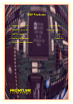
A–10
In Figure A–5, correct the signal names for pins 1–16, 28–45, 57–71, and 78–141; change
the signal name on pin 122 to X2/CLKIN.
113
112
111
110
109
117
116
115
114
121
120
119
118
125
124
123
122
129
128
127
126
133
132
131
130
137
136
135
134
1
2
3
4
5
6
7
8
9
10
11
12
13
14
15
16
17
18
19
20
21
22
23
24
25
26
27
28
29
30
31
32
33
34
35
36
108
107
106
105
104
103
102
101
100
99
98
97
96
95
94
93
92
91
90
89
88
87
86
85
84
83
82
81
80
79
78
77
76
75
74
73
(PGE package)
69
70
71
72
65
66
67
68
61
62
63
64
57
58
59
60
53
54
55
56
49
50
51
52
45
46
47
48
VSSD
V SSD
D7
D6
NC
D5
D4
D3
NC
D2
D1
D0
HCNTL0
TMS
HCNTL1
VDDD
VDDD
TCK
VSSD
VSSD
NC
HR/W
INT1
INT2
INT3
INT4
HBIL
NMI
DR
BDR
FSR
CLKR
V DDA
V DDA
HAS
NC
41
42
43
44
(Top view)
37
38
39
40
HINT
EMU0
NC
EMU1/OFF
VSSC
VSSC
TOUT
BCLKX
CLKX
VDDC
BFSR
BCLKR
RS
READY
HOLD
NC
BIO
VDDC
VDDC
IAQ
TRST
VSSI
VSSI
MP/MC
D15
D14
D13
NC
D12
D11
D10
D9
NC
D8
VDDD
VDDD
141
140
139
138
144
143
142
VDDC
VDDI
VDDI
NC
CKLOUT1
XF
HOLDA
BDX
DX
HD7
BFSX
HD6
FSX
HD5
CLKMD2
HD4
VSSI
VSSI
TDO
NC
VDDC
X1
X2/CLKIN
CLKMD3
NC
BR
HD3
NC
STRB
R/W
PS
IS
DS
HD2
VSSC
VSSC
Figure A–5. Pin/Signal Assignments for the ’C57S in 144-Pin TQFP
Note:
NC
These pins are not connected (reserved).
14
WE
HD1
RD
HD0
HRDY
VDDA
A15
NC
A14
A13
A12
NC
A11
A10
CLKMD1
VSSA
VSSA
TDI
HDS1
HDS2
VDDI
VDDI
A9
A8
A7
NC
A6
A5
A4
A3
NC
A2
A1
A0
VSSA
HCS
Page:
Change or Add:
A–11
In Table A–5, correct the signal names for pins 1–16, 28–45, 57–71, and 78–141; change the
signal name on pin 122 to X2/CLKIN; reorder the signal names.
Table A–5. Signal/Pin Assignments for the ’C57S in 144-Pin TQFP
Signal
Pin
Signal
Pin
Signal
Pin
Signal
Pin
Signal
Pin
A0
75
CLKX
9
HD0
105
TCK
54
VSSD
37
A1
76
D0
48
HD1
107
TDI
91
VSSD
38
A2
77
D1
47
HD2
111
TDO
126
VSSD
55
A3
79
D2
46
HD3
118
TMS
50
VSSD
56
A4
80
D3
44
HD4
129
TOUT
7
VSSI
22
A5
81
D4
43
HD5
131
TRST
21
VSSI
23
A6
82
D5
42
HD6
133
VDDA
69
VSSI
127
A7
84
D6
40
HD7
135
VDDA
70
VSSI
128
A8
85
D7
39
HDS1
90
VDDA
103
WE
108
A9
86
D8
34
HDS2
89
VDDC
10
X1
123
A10
95
D9
32
HINT
1
VDDC
18
X2/CLKIN
122
A11
96
D10
31
HOLD
15
VDDC
19
XF
139
A12
98
D11
30
HOLDA
138
VDDC
124
{
3
A13
99
D12
29
HRDY
104
VDDC
144
{
16
A14
100
D13
27
HR/W
58
VDDD
35
{
28
A15
102
D14
26
IAQ
20
VDDD
36
{
33
BCLKR
12
D15
25
INT1
59
VDDD
52
{
41
BCLKX
8
DR
65
INT2
60
VDDD
53
{
45
BDR
66
DS
112
INT3
61
VDDI
87
{
57
BDX
137
DX
136
INT4
62
VDDI
88
{
72
BFSR
11
EMU0
2
IS
113
VDDI
142
{
78
BFSX
134
EMU1/OFF
4
MP/MC
24
VDDI
143
{
83
BIO
17
FSR
67
NMI
64
VSSA
74
{
97
BR
119
FSX
132
PS
114
VSSA
92
{
101
CLKMD1
94
HAS
71
RD
106
VSSA
93
{
117
CLKMD2
130
HBIL
63
READY
14
VSSC
5
{
120
CLKMD3
121
HCNTL0
49
RS
13
VSSC
6
{
125
CLKOUT1
140
HCNTL1
51
R/W
115
VSSC
109
{
141
CLKR
68
HCS
73
STRB
116
VSSC
110
† These pins are not connected (reserved).
15
Page:
Change or Add:
D–2
In Figure D–1, change the PD pin 5 from +5V to VDD.
Figure D–1. Header Signals and Header Dimensions
TMS
TDI
PD (VDD)
TDO
TCK_RET
TCK
EMU0
1
2
3
4
5
6
7
8
9
10
11
12
13
14
TRST
GND
No pin (key)
GND
GND
GND
EMU1
Header Dimensions:
Pin-to-pin spacing: 0.100 in. (X,Y)
Pin width: 0.025 in. square post
Pin length: 0.235 in., nominal
In Table D–1, change the voltage for pin 5 (the PD pin) from +5V to VDD.
Table D–1.
XDS510 Header Signal Description
Pin
Signal
5
PD
State
I
Target
State Description
O
16
Presence detect. Indicates that the emulation
cable is connected and that the target is
powered up. PD should be tied to VDD in the
target system.
Page:
Change or Add:
D–5
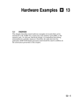
In Figure D–2, change the voltages from +5V to VDD.
Figure D–2. Emulator Cable Pod Interface
VDD
180 Ω
270 Ω
JP1
TDO (Pin 7)
Q
74F175
Q
D
33 Ω
258
GND (Pins 4,6,8,10,12)
33 Ω
TDI (Pin 3)
VDD
10 MHz
10 kΩ
10 kΩ
1034
VDD
180 Ω
270 Ω
JP2
1004
TCK_RET (Pin 9)
PD (Pin 5)
100 Ω
CL
74
NOTE:
All devices are 74AS, unless otherwise specified.
17
TCK (Pin 11)
1034
EMU0 (Pin 13)
EMU1 (Pin 14)
TMS (Pin 1)
TRST (Pin 2)
Page:
Change or Add:
D–7
In Figure D–4, change the voltages from +5V to VDD.
Figure D–4. Target-System Generated Test Clock
Greater than
6 inches
VDD
’C5x
VDD
Emulator header
13
EMU0
14
EMU1
2
TRST
1
TMS
3
TDI
7
TDO
TCK
NC
11
9
EMU0
5
PD
EMU1
TRST
GND
TMS
GND
TDI
GND
TDO
GND
TCK
GND
4
6
8
10
12
TCK_RET
GND
System test clock
In Figure D–5, change the voltages from +5V to VDD.
Figure D–5. Multiprocessor Connections
’C5x
VDD
EMU1
TCK
VDD
TDI
TRST
TDO
TMS
EMU1
EMU0
TCK
TDI
TRST
TDO
EMU0
’C5x
TMS
D–8
Emulator header
13
14
2
1
3
7
11
9
EMU0
PD
5
EMU1
TRST
GND
TMS
GND
TDI
GND
TDO
GND
TCK
GND
4
6
8
10
12
TCK_RET
GND
18
Page:
Change or Add:
D–9
In Figure D–6, change the voltages from +5V to VDD.
Figure D–6. Emulator Connections Without Signal Buffering
Less than
6 inches
VDD
’C5x
VDD
Emulator header
13
EMU0
14
EMU1
2
TRST
1
TMS
3
TDI
7
TDO
11
TCK
9
EMU0
PD
5
EMU1
TRST
GND
TMS
GND
TDI
GND
TDO
GND
TCK
GND
4
6
8
10
12
TCK_RET
GND
D–10
In Figure D–7, change the voltages from +5V to VDD.
Figure D–7. Buffered Signals
Greater than
6 inches
VDD
’C5x
VDD
Emulator Header
13
EMU0
14
EMU1
2
TRST
1
TMS
3
TDI
7
TDO
11
TCK
9
EMU0
PD
5
EMU1
TRST
GND
TMS
GND
TDI
GND
TDO
GND
TCK
GND
4
6
8
10
12
TCK_RET
GND
19
IMPORTANT NOTICE
Texas Instruments and its subsidiaries (TI) reserve the right to make changes to their products or to discontinue
any product or service without notice, and advise customers to obtain the latest version of relevant information
to verify, before placing orders, that information being relied on is current and complete. All products are sold
subject to the terms and conditions of sale supplied at the time of order acknowledgement, including those
pertaining to warranty, patent infringement, and limitation of liability.
TI warrants performance of its semiconductor products to the specifications applicable at the time of sale in
accordance with TI’s standard warranty. Testing and other quality control techniques are utilized to the extent
TI deems necessary to support this warranty. Specific testing of all parameters of each device is not necessarily
performed, except those mandated by government requirements.
CERTAIN APPLICATIONS USING SEMICONDUCTOR PRODUCTS MAY INVOLVE POTENTIAL RISKS OF
DEATH, PERSONAL INJURY, OR SEVERE PROPERTY OR ENVIRONMENTAL DAMAGE (“CRITICAL
APPLICATIONS”). TI SEMICONDUCTOR PRODUCTS ARE NOT DESIGNED, AUTHORIZED, OR
WARRANTED TO BE SUITABLE FOR USE IN LIFE-SUPPORT DEVICES OR SYSTEMS OR OTHER
CRITICAL APPLICATIONS. INCLUSION OF TI PRODUCTS IN SUCH APPLICATIONS IS UNDERSTOOD TO
BE FULLY AT THE CUSTOMER’S RISK.
In order to minimize risks associated with the customer’s applications, adequate design and operating
safeguards must be provided by the customer to minimize inherent or procedural hazards.
TI assumes no liability for applications assistance or customer product design. TI does not warrant or represent
that any license, either express or implied, is granted under any patent right, copyright, mask work right, or other
intellectual property right of TI covering or relating to any combination, machine, or process in which such
semiconductor products or services might be or are used. TI’s publication of information regarding any third
party’s products or services does not constitute TI’s approval, warranty or endorsement thereof.
Copyright 1998, Texas Instruments Incorporated