1
User’s guide
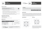
Preamble
This notice includes all the advice and warnings that enables a correct set up and a safe use of the product.
TPL Vision can not be responsible for the bad use of the notice. If so, TPL Vision cancels the guarantee’s effects.
unpacking
Products are packed in our factory, using suitable materials for a safe transport through the usual means of
transportation, in France and abroad. However, a damaged package must be reported to the carrier on delivery.
Hand-written reservations must be indicated on the delivery order. Moreover, please send a letter or an email
to TPL Vision as soon as possible (up to 24 hours after the delivery). If the transportation damage has not been stipulated on the delivery order and reported to TPL Vision in time, the package will not be taken back nor exchanged.
To open the package, do not use any cutting blade so as to avoid damages on the product. Please use the delivered
accessories, if needed (do not use any other products or equivalents to replace the delivered accessories).
RISk class
The EN-62471 norm about lighting fluxes enables the classification of led lightings in 4 distinct groups, according
to their hazardousness degree. Please find below an indicative table, recapitulating the classes of risk for our
standard products.
Colour
Class
Risk
White WHI, Green 525 nm, Red 630 nm
0
none
UV 405 nm, Blue 470 nm, IR 850 nm
1
low
UV 365 nm
2
moderate
UV 385 nm
3
high
In all cases, TPL Vision recommends
the use of the protection glasses
that are listed in its catalog.
For more information about photobiological risks, do not hesitate to
contact us.
TPL Vision can provide calculation notes about the nominal distance of eye risks (security distance).
Beware to the infrared light, invisible to the eyes.
To know if the light is on, please refer to the LED indicators.
User’s guide
P2/8
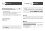
Dimensions
Length
(mm)
Width
(mm)
Height
(mm)
Height with
fixing plate
(mm)
Diameter
of central
hole (mm)
A
B
C
C + 10 mm
D
45
55
65
Min : 200
Max : 1900
Min : 200
Max : 900
• Useful surface: A x B
• Max. useful surface: 0.88 m2
• Max. useful perimeter: 4.5 m
• Total surface (connector excluded): (A + 4mm) x (B + 4mm)
fixing on the machine
During the set up, the light has to be switched off and unplugged. Please use the fixing groove or holes designed
for that purpose. We recommend the using of nuts (supplied) in the groove or M4 screws (not supplied) with
a tightening torque from 0.5 to 1.5 Nm. We also recommend the use of a threadlocker (not supplied) to avoid any
risk of loosening.
FIXING ON THE LENGTH (groove)
FIXING ON THE CORNER
M4 nut
max. depth:
5mm
(4 M4 nuts – supplied)
(CHC screw M3x20 – not supplied)
P3/8
Beware to the use of angle brackets.
Do not hang up.
Do not deform the structure.
camera fixing
125
Length:
125 mm
Width:
125 mm
Height:
10 mm
Screw:
M6
125
62.5
62.5
133
113
93
10
1.5
M6
User’s guide
P4/8
led INDICATORS & potentiomETER
LED indicator
strobe mode
Singleturn
potentiometer 20%-100%
LED indicator
functioning mode
WIRING
STANDARD VERSION
SURFACE ≤ 0.5M² :
1 wiring
OVERDRIVE VERSION
SURFACE > 0.5M² :
1 wiring
SURFACE ≤ 0.25M² :
1 wiring
0.25M² < SURFACE < 0.88M² :
2 wirings
M12 connector
M12 connector
M12 connector
or
or
and
Cable
Cable
Cable
Cable
Potentiometer setting
Standard version:
• Lowest level of the potentiometer: 20% of the power.
• Highest level of the potentiometer: 100% of the power (350mA/led).
Overdrive version:
When the product is delivered, the potentiometer is set at 30%, and the product can be used in continuous mode. To use it in Overdrive (lighting power x3 when the potentiometer is set at 100%), you must
absolutely respect a maximum lighting time of 3ms and a maximum duty cycle of 10%.
P5/8
Connection
M12 Connector 4 male points
STROBE PNP :
POWER CONNECTOR – T CODING
4
+ 24 V
brown
black
1 + 24 V
2
3 Ground
4 PNP
STROBE
PNP
1
3
blue
STROBE NPN :
1 + 24 V
2 NPN
3 Ground
4
GND
CONTINUOUS MODE :
2
white
STROBE
1 + 24 V
2
3 Ground
4 PNP
NPN
STROBE mode :
PNP : from 5 to 24V for 100% ON. From 0 to 1V for 100% OFF.
NPN : less than 1V for 100% ON. Above 2V for 100% OFF. Max 20V.
Voltage drop for Connector M12 + wire 10 meters:
(Minimum Voltage at the product input: 20VDC)
1.15V @ 5A
2.3V @ 10A
1 + 24 V
2 NPN
3 Ground
4
or
3.5V @ 15A
4.6V @ 20A
Max 20A
Cable 4 wires
2
+ 24 V
brown
white
STROBE PNP :
STROBE
NPN
1
3
4
black
blue
1 + 24 V
2
3 Ground
4 PNP
GND
1 + 24 V
2 NPN
3 Ground
4
STROBE
PNP
CONTINUOUS MODE :
1 + 24 V
2
3 Ground
4 PNP
STROBE mode :
PNP : from 5 to 24V for 100% ON. From 0 to 1V for 100% OFF.
NPN : less than 1V for 100% ON. Above 2V for 100% OFF. Max 20V.
Voltage drop for Cable 10 meters:
(Minimum Voltage at the product input: 20VDC)
STROBE NPN :
1.15V @ 5A
2.3V @ 10A
3.5V @ 15A
1 + 24 V
2 NPN
3 Ground
4
or
4.6V @ 20A
Max 20A
User’s guide
P6/8
Overdrive version
Wiring recommendation
WIRING 1
WIRING 2
Control and power
Power
4
3
1
2
24 V
3 4
1 2
GND
In the OVERDRIVE version, both wirings
can be powered by
THE SAME POWER SUPPLY 24V.
TECHNICAL INFORMATION
Features
Consumption
Min. functioning Voltage
Normal functioning Voltage
Max. functioning Voltage
Max. consumption Strobe signal
Operating temperature
MFDOME+
MFDOME+ Overdrive
1,32W par 25cm²
in peak and on average
3W/25cm² in peak max
0,43W/25cm² max
on average (3ms@10%)
20V in the light input
24V in the light input (±10%)
30V in the light input
5mA
-10° to +40°C / 80% of humidity without condensation
No thermal shock (max temperature variation: 10°C in 24h)
P7/8
User security
Do
Do
Do
Do
respect the power supply voltages and the connection terminals.
not modify or dismantle all or part of the product.
not connect or clean when power is on.
not watch the lighting source directly, and follow the advice below :
• If the workstation enables it, interpose a filter that will stop the lighting radiation under fixed or adjustable
frame between the source and the operator.
• When these measures cannot be implemented, supply the operators with glasses (class 4) available for sale
at TPL Vision, or with a dedicated protective mask, that will stop the lighting radiation.
• Forbid or limit the direct access to the lighting source (exposure into the radiation axis).
• Establish a security perimeter so as to prevent the operators from approaching the lighting source beyond
the recommendations of the manufacturer, as for eye irritation is concerned.
• In any case, ensure that the chosen means properly reduce the exposition quantities (features of screens or
glasses to be chosen, according to the wavelengths that the operators are exposed to).
Equipment maintenance
Cleaning (when the product is switched off)
Please use a soft and dry cloth.
Do not use any abrasive material.
Do not use any cleaning solvent or aggressive chemical product – isopropyl alcohol.
Version B-2, 2015/07 edition.
www.tpl-vision.com
Features and presentations liable to changes without notice.
20 rue de Saint Philbert – 44118 La Chevrolière – France
Tel. + 33(0)2 40 56 10 99 – Fax. + 33(0)2 40 56 42 89