1
USER’S GUIDE
TABLE OF CONTENTS:
Introduction . . . . . . . . . . . . . . . . . . . . . . . . . . . . . . . . . . . . . . . . . . . . . . . . . . . . . . . . . . . . .3
Features . . . . . . . . . . . . . . . . . . . . . . . . . . . . . . . . . . . . . . . . . . . . . . . . . . . . . . . . . . . . . . .3
Important Safeguards And Precautions . . . . . . . . . . . . . . . . . . . . . . . . . . . . . . . . . . . . . . .3
The Front Panel . . . . . . . . . . . . . . . . . . . . . . . . . . . . . . . . . . . . . . . . . . . . . . . . . . . . . . . . . .4
The Rear Panel . . . . . . . . . . . . . . . . . . . . . . . . . . . . . . . . . . . . . . . . . . . . . . . . . . . . . . . . . .5
The Speaker Cabinet Input Plate . . . . . . . . . . . . . . . . . . . . . . . . . . . . . . . . . . . . . . . . . . . .5
Important Information About Tubes And Tube Products
A Brief history Of The Tube . . . . . . . . . . . . . . . . . . . . . . . . . . . . . . . . . . . . . . . . . . . . .6
Tube Types And Usage . . . . . . . . . . . . . . . . . . . . . . . . . . . . . . . . . . . . . . . . . . . . . . . .6
The Nature Of Tubes: Why (And When) To Replace Them . . . . . . . . . . . . . . . . . . . . .6
The Importance Of Proper Biasing . . . . . . . . . . . . . . . . . . . . . . . . . . . . . . . . . . . . . . .7
Survival Tips For Tube Amplifiers . . . . . . . . . . . . . . . . . . . . . . . . . . . . . . . . . . . . . . . .7
Some Suggested Settings . . . . . . . . . . . . . . . . . . . . . . . . . . . . . . . . . . . . . . . . . . . . . . . . .7
Technical Specifications . . . . . . . . . . . . . . . . . . . . . . . . . . . . . . . . . . . . . . . . . . .back cover
System Block Diagram . . . . . . . . . . . . . . . . . . . . . . . . . . . . . . . . . . . . . . . . . . . .back cover
Declaration Of Conformity
#35, Effective 01-01-2001
Manufacturer’s Name:
Production Facility:
Production Facility:
Shipping Facility:
Office Facility:
SLM Electronics
1901 Congressional Drive, St. Louis, MO 63146, USA
700 Hwy 202 W, Yellville, AR 72687, USA
1400 Ferguson Ave., St. Louis, MO 63133, USA
1400 Ferguson Ave., St. Louis, MO 63133, USA
Product Type:
Audio Amplifier
Complies with the following Standards:
Safety:
EN60065, E60065, C22.2, UL6500 and/or UL813
EMC:
Directive 89/336/EEC, EN55103, EN55013, EN61000,
and/or FCC 47CFR 15B clA
Supplementary information provided by:
SLM Electronics - R & D Engineering
1901 Congressional Drive, St Louis, MO 63146, USA
Tel.: 314-569-0141, Fax: 314-569-0175
CAUTION
PRECAUCION
ATTENTION
RISK OF ELECTRIC SHOCK
DO NOT OPEN
RIESGO DE CORRIENTAZO
NO ABRA
RISQUE D'ELECTROCUTION
NE PAS OUVRIR
WARNING: TO REDUCE THE RISK OF FIRE OR ELECTRIC SHOCK, DO NOT EXPOSE
THIS APPARATUS TO RAIN OR MOISTURE. TO REDUCE THE RISK OF ELECTRIC
SHOCK, DO NOT REMOVE COVER. NO USER-SERVICEABLE PARTS INSIDE. REFER
SERVICING TO QUALIFIED SERVICE PERSONNEL.
PRECAUCION: PARA REDUCIR EL RIESGO DE INCENDIOS O DESCARGAS ELECTRICAS, NO PERMITA QUE ESTE APARATO QUEDE EXPUESTO A LA LLUVIA O LA HUMEDAD. PARA DISMINUOIR EL
RIESGO DE CORRIENTAZO. NO ABRA LA CUBIERTA. NO HAY PIEZAS ADENTRO QUE EL USARIO
PUEDO REPARAR DEJE TODO MANTENIMIENTO A LOS TECHNICOS CALIFICADOS.
ATTENTION: PROTÉGEZ CET APPAREIL DE LA PLUIE ET DE L'HUMIDITÉ AFIN D'ÉVITER TOUT
RISQUE D'INCENDIE OU D'ÉLECTROCUTION. POUR REDUIRE D'ELECTROCUTION NE PAS ENLEVER
LE COUVERCLE. AUCUNE PIECE INTERNE N'EST REPRABLE PAR L'UTILISATEUR. POUR TOUTE
REPARATION, S'ADRESSER A UN TECHNICIEN QUALIFIE.
IMPORTANT SAFETY INSTRUCTIONS
• READ, FOLLOW, HEED, AND KEEP ALL INSTRUCTIONS AND WARNINGS.
• DO NOT OPERATE NEAR ANY HEAT SOURCE AND DO NOT BLOCK ANY VENTILATION OPENINGS ON THIS APPARATUS. FOR PROPER OPERATION, THIS UNIT REQUIRES 3”
(75CM) OF WELL VENTILATED SPACE AROUND HEATSINKS AND OTHER AIR FLOW PROVISIONS IN THE CABINET.
• DO NOT USE THIS APPARATUS NEAR SPLASHING, FALLING, SPRAYING, OR STANDING LIQUIDS.
• CLEAN ONLY WITH LINT-FREE DAMP CLOTH AND DO NOT USE CLEANING AGENTS.
• ONLY CONNECT POWER CORD TO A POLARIZED, SAFETY GROUNDED OUTLET WIRED TO CURRENT ELECTRICAL CODES AND COMPATIBLE WITH VOLTAGE, POWER, AND
FREQUENCY REQUIREMENTS STATED ON THE REAR PANEL OF THE APPARATUS.
•
•
•
•
•
•
PROTECT THE POWER CORD FROM DAMAGE DUE TO BEING WALKED ON, PINCHED, OR STRAINED.
UNPLUG THE APPARATUS DURING LIGHTNING STORMS OR WHEN UNUSED FOR LONG PERIODS OF TIME.
ONLY USE ATTACHMENTS, ACCESSORIES, STANDS, OR BRACKETS SPECIFIED BY THE MANUFACTURER FOR SAFE OPERATION AND TO AVOID INJURY.
WARNING: TO REDUCE THE RISK OF ELECTRIC SHOCK OR FIRE, DO NOT EXPOSE THIS UNIT TO RAIN OR MOISTURE.
SERVICE MUST BE PERFORMED BY QUALIFIED PERSONNEL.
OUR AMPLIFIERS ARE CAPABLE OF PRODUCING HIGH SOUND PRESSURE LEVELS. CONTINUED EXPOSURE TO HIGH SOUND PRESSURE LEVELS CAN CAUSE PERMANENT HEARING IMPAIRMENT OR LOSS. USER CAUTION IS ADVISED AND EAR PROTECTION IS RECOMMENDED IF UNIT IS OPERATED AT HIGH VOLUME.
EXPLANATION OF GRAPHICAL SYMBOLS:
EXPLICACION DE SIMBOLOS GRAFICOS:
EXPLICATION DES SYMBÔLES GRAPHIQUES:
2
"DANGEROUS VOLTAGE"
=
“VOLTAJE PELIGROSO”
"DANGER HAUTE TENSION"
"IT IS NECESSARY FOR THE USER TO REFER TO THE INSTRUCTION MANUAL"
=
“ES NECESARIO QUE EL USUARIO SE REFIERA AL MANUAL DE INSTRUCCIONES.”
"REFERREZ-VOUS AU MANUAL D'UTILISATION"
INTRODUCTION:
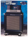
Thank you for selecting the Ampeg B-15R Portaflex Bass Amplifier. Revived from the past and enhanced for the present,
this limited production model offers all of the best features of the 1960’s classic plus more. In order to get the most out of
your new amplifier, please read this user’s guide before its use.
FEATURES:
• 0db and -15dB Input Jacks
• Ultra High / Ultra Low Boosts
• Input Gain Control
• Three Band EQ
• Five Position Mid Freq Select
• Master Volume Control
• Half-Power Switch
• Tube Bias Select Switch
• Impedance Selector (8/4 Ohms)
• Line Out/Line In jacks
• XLR Balanced Line Out Jack
• Line Out Level Control
• Pre/Post Select Switch
• Ground Lift Switch
•
•
•
•
•
•
•
Patented “Flip Top” Enclosure
Ampeg Vintage 15” Speaker
H.F. Horn w/Level control
100 watts RMS
All Tube Design
Removable Dolly Board w/Casters
Proudly Made In America
IMPORTANT SAFEGUARDS AND PRECAUTIONS:
All Ampeg products are designed for continuous safe operation, as long as common sense is used and steps are taken
to help avoid certain problems. Abiding by the following rules can help prevent damage to your equipment, yourself, and
others.
• The unit is equipped with a three-pronged AC power cord. To reduce the risk of electrical shock, NEVER remove
or otherwise attempt to defeat the ground pin of the power cord.
• Connect the unit ONLY to a properly grounded AC outlet of the proper voltage for your unit.
• Avoid sudden temperature extremes, rain and moisture. Also, avoid sudden and intense impact. (If the unit has
been subjected to any of the preceding abuses, have it looked at by an authorized service center.)
• NEVER set the unit on a support that might give out under its weight.
• Always keep the total speaker impedance at or above the rated load.
• Unplug the unit before cleaning it. NEVER spray liquid cleaners onto the unit. Wipe it with a slightly dampened,
lint-free cloth to remove dirt and film.
• Do not use the unit if it has sustained damage to the chassis, controls, or power cord. Refer the unit to an
authorized service center for inspection.
• Audio equipment capable of producing high volume levels are also capable of inflicting permanent hearing loss
or damage, if the exposure to such levels is prolonged. Such damage is progressive and irreversible! Consider
using quality hearing protection devices.
3
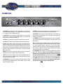
THE FRONT PANEL:
3
1
2
4
5
6
7
1. 0dB INPUT: If your instrument has normal pickups, connect it here by
means of a shielded signal cable. If your instrument has active electronics
or “hot” pickups, use the -15dB Input jack (#2).
2. -15dB INPUT: If your instrument has active electronics or “hot” pickups,
connect it here by means of a shielded signal cable. If your instrument has
normal pickups, use the 0dB Input jack (#1).
3. ULTRA HI: This switch, when depressed, boosts the high frequencies.
4. ULTRA LO: This switch, when depressed, boosts the low frequencies.
5. GAIN: Use this control to adjust the input gain of the amplifier to your
instrument and playing style. With a low instrument output and a soft playing style, this control would be set higher than with higher outputs and harder playing styles. Proper setting of the Gain control will produce clean output with the lowest noise level. Use this control in conjunction with the
Master control (#10).
6. BASS: Use this control to adjust the output level of the low frequencies.
This control provides an adjustment range of 25dB at 40Hz.
7. MID: Use this control to adjust the output level of the middle frequencies.
This control provides an adjustment range of 34dB at the frequency selected by the Frequency control (#8).
8. FREQUENCY: Use this control to select the midrange frequency: 200Hz
(at the fully counter clockwise position), 400 Hz, 900Hz, 1.5kHz, or 2.5kHz
(at the fully clockwise position).
4
8
9
10
11
12
13
9. TREBLE: Use this control to adjust the output level of the high frequencies. This control provides an adjustment range of 30dB at 4kHz.
10. MASTER: Use this control to adjust the output level of the amplifier and
the output level at the Balanced Line Out jack (#24) when the Post/Pre
switch (#22) is depressed.
11. 100W/60W: Use this switch to choose whether the output of the amplifier is full power (switch at the 100W position) or half power (switch at the
60W position).
Note: In the 60W position the amplifier will deliver approximately 40 watts to
the internal 8 ohm speaker. To deliver the full 60 watts to the internal speaker, set the Impedance Selector switch (#18) to the 4 Ohms position.
Operation at either the 4 or 8 Ohms position is acceptable and will produce
tonal variances. Experiment with these settings to determine which setting
provides the best results for your application.
12. ON/STANDBY: Use this switch to activate the amplifier after the On/Off
switch (#13) is turned on. Always turn the On/Standby switch OFF first
and ON last! Turn the On/Off switch (#13) on at least 30 seconds before
turning on the On/Standby switch. During short breaks you should set this
switch to the Standby position to help prolong the life of the amplifier’s tubes.
13. ON/OFF: Use this switch to turn the amplifier on and off. Always turn
this switch ON first and OFF last! Turn the On/Standby switch (#12) on
at least 30 seconds after turning on the On/Off switch.
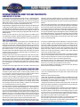
THE REAR PANEL:
MODEL: B-15
SERIAL: B1500691242
LINE: 120 V ~ 60
Hz
WATTS:
MAX
22
15
16
17
18
19
20
24
21
23
14
14. AC LINE IN: Firmly insert the female end of the supplied AC power cord
into this socket. The grounded power cord should only be plugged into a
grounded power outlet that meets all applicable electrical codes and is
compatible with the voltage, power and frequency requirements stated on
the rear panel. Do not attempt to defeat the safety ground connection!
22. POST/PRE: This switch, when depressed, sends a pre-eq signal to the
Balanced Line Out jack (#24), which is not affected by the settings of the
tone controls or master level controls. When this switch is in the out position, the signal sent to the Balanced Line Out jack (#24) is post-eq, and is
affected by the settings of the tone controls and master level control.
15. FUSE: The B-15R employs a fuse to help protect the amplifier from
damage due to overload conditions. If the fuse fails, replace it only with the
same size and type.
23. LIFT/GND: This switch, when depressed, lifts the chassis ground connection at the Balanced Line Out jack (#24). This switch should only be
depressed if there is excessive buzzing or hum coming from the amplifier
due to ground loops.
16. BIAS SELECT: Use this switch to match the bias to the type of output
tube you are using. The B-15R is shipped from the factory with 6L6 output
tubes and the Bias Select switch set to the 6L6 position. The only time you
would need to change this switch is when installing EL34 output tubes.
17. SPEAKERS: Use these jacks to connect the amplifier to the internal
speaker and/or an extension speaker. Use heavy duty speaker cables terminated with the proper connectors. The total speaker impedance must be
no less than four ohms and the Impedance Selector switch (#18) must be
set to match the total impedance. The B-15R’s cabinet impedance is rated
at eight ohms.
18. IMPEDANCE SELECTOR: Use this switch to match the amplifier to the
total impedance of your speaker cabinet(s). Use the chart which follows
determine the total impedance of parallel cabinets:
24. BALANCED LINE OUT: Use this XLR jack to connect a balanced line
level signal to a mixing console, recording device, or external amplifier.
THE SPEAKER CABINET INPUT PLATE:
B-15R
SERIAL #
POWER HANDLING: 150 WATTS
IMPEDANCE: 8 OHMS
HIGH FREQUENCY
47-267-01
MADE IN THE U.S.A. BY
SLM ELECTRONICS
1400 FERGUSON AVE.
ST. LOUIS, MO 63133
ATTENUATOR
OFF
–6
25
CABINET IMPEDANCE
16 ohms
16 ohms
8 ohms
# OF CABINETS
2
4
2
TOTAL IMPEDANCE
8 ohms
4 ohms
4 ohms
19. LINE OUT: Use this jack to send a line level signal from the amplifier to
an external amplifier, a mixing console, or the input of an external effect.
20. LINE IN: Use this jack to return the signal from an external effect to the
amplifier.
21. LINE OUT LEVEL: Use this control to adjust the signal level at the
Balanced Line Out jack (#24).
FULL RANGE
INPUTS
0
26
25: HIGH FREQUENCY ATTENUATOR: Use this three-position rotary
switch to adjust the output level of the internal high frequency driver. Use
the tip of a flatblade screwdriver to set this switch to the position which best
suits your tastes and playing environment.
26: FULL RANGE INPUTS: Use either of these jacks to connect the internal speaker to the B-15R’s Speaker jack (#17) by means of a heavy duty
speaker cable. Use the remaining jack to connect to the input jack of an
extension speaker cabinet if desired.
5
IMPORTANT INFORMATION ABOUT TUBES AND TUBE PRODUCTS:
A BRIEF HISTORY OF THE TUBE:
In 1883, Edison discovered that electrons would flow from a suspended filament
when enclosed in an evacuated lamp. Years later, in 1905, Fleming expanded on
Edison's discovery and created the "Fleming Valve". Then, in 1907, Dr. Lee de Forest
added a third component – the grid – to the "Fleming's Valve" and the vacuum tube
was a fact of life. The door to electronic amplification was now open.
During World War II, data gleaned from their intensive research on the detectors used
in radar systems led Bell Telephone Laboratories to the invention of the transistor.
This reliable little device gained quick support as the new component for amplification. The death of the vacuum tube seemed imminent as designers, scientists, and
engineers reveled in the idea of replacing large, fragile glass tubes with these small,
solid-state devices.
However, there were (and still are) many serious listeners who realized that the
sound produced by a "transistor" amplifier is significantly different from that produced
by a tube amplifier with identical design specifications. They considered the sound
produced by these new solid-state devices to be hard, brittle, and lifeless. It was
determined that solid-state devices produced a less musical set of harmonics than
tubes. When pushed past their limits, they tend to mute the tone and emphasize the
distortion.
Tubes, on the other hand, produce a more musical set of harmonics, the intensity of
which can be controlled by the player. This characteristic adds warmth and definition
to the sound which has become the hallmark of tube amplifiers. When tubes are driven into clipping, the harmonic overtones can be both sweet and pleasing or intense
and penetrating, depending on the musician’s musical taste and playing technique.
Over the years, application engineers have designed a number of outstanding solidstate amplifiers that sound very, very good. Some use special circuitry which enables
them to simulate the distortion characteristics of a tube amplifier. However, the tube
amplifier, still held in the highest esteem by many musicians, offers a classic "vintage"
sound in a contemporary market.
TUBE TYPES AND USAGE:
Tube amplifiers are based primarily on two types of tubes – preamplifier tubes and
power tubes. The tubes used in preamplifiers (12AX7, 12AU7, 12AT7, etc.) are
smaller than the power tubes. These tubes amplify the signal from your instrument
and shape the sound. They are inherently microphonic (mechanically pick up and
transmit external noises). Since these tubes are used in the critical first stages of a
tube amplifier's circuitry, it is very important to use high-quality, low noise/low
microphonic tubes for this application. Although tubes of this quality may be difficult
to find and typically cost more than "off-the-shelf" tubes, the improvement in performance is worth the investment.
Preamplifier tubes are also used to drive the power tubes. When used in this application, a 12AX7 will produce a more distorted tone than a 12AT7, which produces
a clearer, sweeter sound. A 12AU7 is even cleaner and brighter than a 12AT7, giving more definition to the sound. (In some cases it is possible to change the sound
by changing the type of preamp and/or driver tubes. When making any modification to your equipment, it is highly recommended that you consult with a qualified
service center.)
The power tubes are the largest tubes used in an amplifier. These tubes convert
the low-level, conditioned signal from the preamplifier into a level that is sufficient
to drive the speakers. There are several types of power tubes available, each of
which offers a different performance/sound characteristic. For example, the EL34
power tube produces a great Classic rock sound. When an EL34 is driven into distortion it produces a unique sound ("crunch"). When compared to the 6L6, the EL34
distorts more quickly, exhibits a "looser" low-end response and produces more
harmonics at mid and high frequencies ("creamier" sound). These differences
become more noticeable at higher volumes.
The 6L6 tubes produce a big low-end thump and have a very good dynamic range.
They offer a more traditional "American Rock" sound. The 6V6 tubes produce a
creamy sound with nice distortion. On the other hand, the KT88 produces a big lowend but sounds more like an EL34 in the mid and high frequencies.
The 6550 power tubes are more rugged and stay cleaner sounding even at full
power. When they do distort, the sound produced is more solid and has a tighter
low end; more of a "heavy metal" type distortion with lots of power.
Some tubes are available in matched sets. These tubes have been extensively
tested for optimum performance and longevity.
THE NATURE OF TUBES - WHY (AND WHEN) TO REPLACE THEM:
Tubes are made up of a number of fragile mechanical components that are vacuum-sealed in a glass envelope or bubble. The tube's longevity is based on a number of factors which include how hard and often the amplifier is played, vibration
from the speakers, road travel, repeated set up and tear down, etc.
Any time you notice a change in your amplifier's performance, check the tubes first.
If it's been a while since the tubes were replaced and the sound from your amplifier lacks punch, fades in and out, loses highs or lows or produces unusual sounds,
the power tubes probably need to be replaced. If your amplifier squeals, makes
noise, loses gain, starts to hum, lacks "sensitivity", or feels as if it is working against
you, the preamplifier tubes may need to be replaced.
The power tubes are subjected to considerably more stress than the preamplifier
tubes. Consequently, they almost always fail/degrade first. If deteriorating power
tubes aren't replaced they will ultimately fail. Depending on the failure mode, they
may even cause severe damage to the audio output transformer and/or other components in the amplifier. Replacing the tubes before they fail completely has the
potential to save you time, money and unwanted trouble. Since power tubes work
together in an amplifier, it is crucial that they (if there is more than one) be replaced
by a matched set. If you're on the road a lot, we recommend that you carry a spare
matched set of replacement power tubes and their associated driver tubes.
After turning off the power and disconnecting the amplifier from the power source,
carefully check the tubes (in bright light) for cracks or white spots inside the glass
6
or any other apparent damage. Then, with the power on, view the tubes in a dark
room. Look for preamplifier tubes that do not glow at all or power tubes that glow
excessively red.
Whenever you replace the power tube(s):
• Always have the amplifier's bias voltage checked by a qualified service center.
Improper bias voltage will cause degradation in performance and possibly damage
the tubes and/or the amplifier. (See the section below entitled, "The Importance of
Proper Biasing", for more information on this subject).
• We highly recommend that you replace the driver tube(s) as well. The driver tube
determines the shape and amplitude of the signal applied to the power tube(s) and
has to work almost as hard as the power tube(s).
You can check your preamplifier tubes for microphonics by turning the amplifier on,
turning up the gain and tapping lightly on each tube with the end of a pencil or a
chop stick (my favorite). You will be able to hear the tapping through your speakers, which is normal. It is not normal for a tube to ring like a bell after it’s tapped. If
it does ring then it’s microphonic and should be replaced. Remember to use only
high quality, low microphonic tubes in the preamplifier section.
Even though power tubes are rarely microphonic, you should check them anyway.
The power tubes can be checked for microphonics just like pre-amp tubes.
In the case of very high gain amps, you may be able to reduce the amount of noise
generated by simply swapping the preamp tubes around.
THE IMPORTANCE OF PROPER BIASING:
For the best performance and longest tube life, proper biasing is imperative. Bias
is the negative voltage which is applied to the power tube’s control grid to set the
level of idle current. We cannot over emphasize the difference in warmth of tone
and dynamic response that come with proper biasing. If the bias is set too high
(overbiased), the sound from the amp will be distorted at all levels. If the bias is set
too low, (under biased) the power tubes will run hot (the plates inside the tubes may
glow red due to excessive heat) and the sound from the amplifier will lack power
and punch. The excessive heat greatly reduces tube life – from a few days to as
little as a few hours in extreme cases. Setting the bias on your amp is like setting
the idle on your car. If it’s too high or hot it’s running away with you and if it’s too
low or cold it will choke when you step on it.
The bias is adjusted at the factory in accordance with the type of power tube(s)
installed in your amplifier. It is important to point out that tubes of the same type
and specification typically exhibit different performance characteristics.
Consequently, whenever power tubes are replaced, the bias voltage must be
checked (unless the amplifier is equipped with “self-biasing circuitry”) and readjusted to accommodate the operating parameters of the replacement tubes.
Depending on the model and amplifier type, there may be hum balance controls,
trim pots, or bias adjustment controls on its rear panel. However, the bias adjustment should be performed only by qualified service personnel with the proper, calibrated test equipment.
SURVIVAL TIPS FOR TUBE AMPLIFIERS:
To prolong tube life, observe these tips and recommendations:
• Match the impedance of your speaker cabinet(s) to your amplifier. Improper impedance matching will contribute to early tube degradation and may cause premature tube failure.
• Make sure the speaker(s) are properly connected prior to turning on the amplifier.
• After playing the amplifier, allow sufficient time for it to properly cool down prior to moving it. A properly cooled amplifier prolongs tube life due to the internal components being
less susceptible to the damage caused by vibration.
• Allow the amplifier to warm up to room temperature before turning it on. The heat generated by the tube elements can crack a cold glass housing.
• Replace the output tube(s) before the performance degrades or the tubes fail completely. Replace the tube(s) on a regular basis (at least once per year or as often as every 4
to 6 months if you play long and hard every day).
• Always have the bias checked after replacing the output tubes (unless the amplifier is equipped with "self-biasing circuitry"). This should be done ONLY at a qualified service
center. Improper biasing could result in the tubes running too hot, which greatly reduces the life of the tubes – or too cold, which results in distorted sound regardless of level
settings. Do not play the amplifier if it exhibits these symptoms – get the bias checked/adjusted immediately to prevent tube failure and/or other damage.
• If the locating notch on the base of a power tube breaks off, replace the tube. This significantly reduces the risk of damaging your amplifier by incorrectly inserting the tube.
• Protect the amplifier from dust and moisture. If liquid gets into the amplifier proper, or if the amplifier is dropped or otherwise mechanically abused, have it checked out at an
authorized service center before using it.
• Proper maintenance and cleaning in combination with routine checkups by your authorized service center will insure the best performance and longest life from your amplifier.
CAUTION: Tube replacement should be performed only by qualified service personnel who are familiar
with the dangers of hazardous voltages that are typically present in tube circuitry.
SOME SUGGESTED SETTINGS:
JAZZ:
OUT
IN
FUNK:
AS
NEEDED
AS
NEEDED
AS
NEEDED
AS
NEEDED
AS
NEEDED
AS
NEEDED
OUT
OUT
COUNTRY:
AS
NEEDED
IN
IN
ROCK:
AS
NEEDED
OUT
IN
7
TECHNICAL SPECIFICATONS:
OUTPUT POWER RATING
100 watts @ 5%THD, 8 ohm load, 120VAC
SPEAKER SIZE AND RATING
Ampeg Vintage 15”, 8 ohm, 150 watt, 2” voice coil, 56 oz magnet
High Efficiency Piezo Tweeter, 8 ohm, 150 watt (w/network)
CROSSOVER FREQUENCY
3kHz
ULTRA HIGH SWITCH
6dB Boost @ 4kHz
ULTRA LOW SWITCH
10dB Boost @ 40Hz
BASS CONTROL
25dB Range @ 40Hz
MID CONTROL
34dB Range @ 200, 400, 900, 1.5k or 2.5kHz
TREBLE CONTROL
30dB Range @ 4kHz
INPUT IMPEDANCE
0dB: 3M ohms; -15dB: 47k ohms
MAX. INPUT SIGNAL LEVEL ACCEPTED
0dB: 1V RMS; -15dB: 5.75V RMS
TOTAL SYSTEM GAIN
50dB w/tones flat, Ultra Low and Ultra High off
SIGNAL TO NOISE RATIO
90dB
POWER REQUIREMENTS
120VAC, 60Hz, 400VA
100VAC, 50/60Hz, 400VA
230VAC, 50/60Hz, 400VA
DIMENSIONS
24”W x 16-1/2”D x 24-1/4”H w/amp flipped inside, w/out caster board
32-7/8” H w/amp flipped out, w/out caster board; 37-1/4” H w/caster board
WEIGHT:
117 lbs
Ampeg continually develops new products, as well as improves existing ones. For this reason,
the specifications and information in this publication are subject to change without notice.
SYSTEM BLOCK DIAGRAM:
BALANCED
LINE OUT
PRE
POST
LIFT/
GND
LEVEL
OFF
POWER
TUBES
MID
MASTER
0dB
LINE
OUT
LINE
IN
60W
GAIN
-15dB
BASS TREBLE
ULTRA
LOW
ULTRA
HIGH
100W
FREQUENCY
PHASE
INVERTER
BIAS
www.ampeg.com
Ampeg is proudly Made in America.
©2003 SLM Electronics, 1400 Ferguson Avenue, St. Louis, MO 63133 U.S.A.
P/N 47-667-04 • 110503
-6
0
8 OHMS
4 OHMS
HF
HORN
XO
15"
WOOFER