1
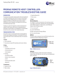
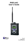
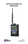
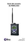
Technical Note TN-183
rev 2 bs.04-05
ProRAE Remote Host Controller:
Communication Troubleshooting Guide
Introduction
1. Power
This technical note provides simple procedures that
can be performed in the field to help identify and
correct the cause of communication failure between
the ProRAE Remote host controller and detectors
equipped with RAELink or RAELink2 remote
wireless modems. Instructions on setup,
configuration, and operation can be found in the
ProRAE Remote User’s Guide.
Start-Up Sequence
The sequence in which the components of the system
are turned on can affect communication, especially
when using USB adapters and/or RAELink repeaters.
For best results, use the following sequence when
starting the system:
1. Turn on the host PC.
2. Launch ProRAE Remote.
3. Begin scanning (press the Begin [F9] key).
4. Turn on the host modem:
If setting up a system for the first time, check all
components and establish a radio frequency (RF) link
prior to deploying detectors downrange. If
communication is not established or if
communication fails after some time, proceed to the
troubleshooting steps.
RAELink:
The power switch on the back of the host RAELink
should be in the up position and the CD LED
glowing; see Figure 1.
Troubleshooting Steps
The common causes of communication failure can be
grouped into the three major categories listed below.
The remainder of this tech note provides detail on
these troubleshooting steps in the sequence listed:
CD LED
Glowing
1. Power
● Start-up sequence
● Host personal computer (PC) operating
system power settings
Figure 1. RAELink turned on.
RAELink2:
Press ON (on/off power switch) and hold until the
LED glows steadily. Release the ON button when
the Power LED steadily glows green; see Figure 2.
2. Setup
● Software
• Compatibility with Firmware
• Communication port
• Units displayed
● Hardware
• Host RAELink modem
• Detector mode of operation
• Unit ID
• Antennas and battery packs
• Network ID
Power
LED
Glowing
Figure 2. RAELink2 turned on.
3. Interference
● Duplicate Unit IDs
● Wave coupling
● Duplicate Network IDs
● Other sources
5. Turn on RAELink repeater if one is being
deployed*.
*Note: For complete instructions on deploying
repeaters and precautions to take when deploying
RAE Systems Inc.
1
3775 N. First St., San Jose, CA 95134-1708 USA
Phone: +1.888.723.8823
Email: [email protected]
Web Site: www.raesystems.com
Technical Note TN-183
rev 2 bs.04-05
multiple repeaters, refer to Technical Note TN-184:
RAELink Repeater Deployment Procedures.
Figure 3. Power Options Properties.
For Windows® operating systems, the power settings
can be verified under:
6. Turn on passive monitor PC(s) if any are to be
used.
7. Turn on passive RAELink modem(s) as
necessary for passive monitors.
8. Turn on RAE Systems wireless detector(s).
9. Turn on remote RAELink modem(s).
AreaRAE detectors come equipped with an internally
housed remote RAELink modem that needs to be
turned on by activating the RADIO button. Other
RAE Systems wireless detectors are connected to a
remote RAELink modem via the serial
communication port. Ensure that all of these remote
transceivers are turned on by following the same
procedures for turning on the host modem.
Classic View
Category View
● Start
●Control Panel
●Power settings
●Start
●Control Panel
●Performance & Maintenance
-Power Options
2. Setup
Compatibility With Firmware
Refer to Table 1 to verify that the firmware on the
detectors and the version of the ProRAE Remote are
compatible for wireless communication. The
firmware version of the detector is listed as the unit
goes through its initial warm-up sequence.
Note: RAE Systems Detectors and RAELink modems
are equipped with rechargeable battery packs. The
detectors can also run on alkaline batteries via the
alkaline adapter provided in the kit. Communication will
fail when batteries near complete depletion. The entire
system can run continuously using the AC power
adapters if the application classification requirements
permit this option.
Note: In addition to the correct firmware, MultiRAE,
MiniRAE 2000, and ppbRAE Plus detectors require
the wireless communication protocol within the
firmware to be enabled. This is performed at RAE
headquarters at the time of purchase, or can be done
as an upgrade.
Operating System Power Settings
If the hosts PC’s power settings turn off the monitor,
turn off the hard disk, or put the system in standby or
hibernate, then ProRAE Remote may malfunction
and will require a reboot. For optimal performance,
it is recommended that these power settings be
disabled; see Figure 3.
DETECTOR
FIRMWARE
ProRAE
ProRAE
ProRAE
V1.30
V1.40
V1.41
MultiRAE
Plus
≥3.11
≥3.11
≥3.11
MiniRAE 2000
≥1.20
≥1.20
≥1.20
ppbRAE Plus
≥1.20
≥1.20
≥1.20
AreaRAE
≥2.30
≥2.30
≥2.30
AreaRAE
Gamma
X
X
≥3.00
Table 1. Compatibility chart of ProRAE Remote
and remote detector firmware.
RAE Systems Inc.
2
3775 N. First St., San Jose, CA 95134-1708 USA
Phone: +1.888.723.8823
Email: [email protected]
Web Site: www.raesystems.com
Technical Note TN-183
rev 2 bs.04-05
The software version can be found by accessing the legend
at the top right within ProRAE Remote; see Figure 4.
Note: For complete instructions on using USB adapters,
refer to TN-170: USB to Serial Port Adapter.
Figure 4. ProRAE Remote legend.
Figure 6. Device Manager.
Communication Port
To access the Device Manager for Windows®
operating systems, proceed to:
The host RAELink is connected to the host PC via a
serial computer interface cable. (A serial-to-USB
adapter is required when connecting to a USB
communication port on the host computer.) The
communication port that the RAELink modem is
connected to must be set within ProRAE Remote.
Enter the setup menu (press the Begin [F9] key), and
under the Host tab enter the correct communication
port number; see Figure 5.
Classic View
Category View
●Start
●Control Panel
●System
●Hardware
●Device Manager
●Ports (COM &
LPT)
●Start
●Control Panel
●Performance &
Maintenance
●Power Options
● System
●Hardware
●Device Manager
●Ports (COM & LPT)
Units Displayed
ProRAE Remote can display up to 32 wireless
detectors. By default, the number of units the
software displays is 8. If any of the sensing units
have a unit ID higher than 8, then the Define Max
Units function must be initiated and the number of
units displayed increased; see Figure 7.
Figure 5. Selecting COM Port.
When using a serial-to-USB adapter, the operating
system may assign a different number to the port in
use. The communication port number can be verified
within the host PC operating system’s Device
Manager; see Figure 6.
Figure 7. Defining Max Unit.
RAE Systems Inc.
3
3775 N. First St., San Jose, CA 95134-1708 USA
Phone: +1.888.723.8823
Email: [email protected]
Web Site: www.raesystems.com
Technical Note TN-183
rev 2 bs.04-05
when installing the antenna. If power issues are
suspected, swapping battery packs with another
detector or switching to the alkaline adapter are quick
ways to isolate a faulty or weak battery pack.
Host RAELink Modem
The RAELink modem connected to the host PC must
be programmed as a host modem, as opposed to a
repeater or remote modem. Host modems can be
identified by the label on top of the RAELink
housing (RAELink Host or RAELink2 Host).
Network ID
All RAELink modems within the system need to
have the same Network ID. The Network ID is
identified on the modem or inside the housing of the
AreaRAE detector. The Network ID can also be
located by contacting RAE Systems’ service
department and providing the serial number of the
RAELink modem. An easy way to isolate the
modems and identify the root cause of
communication failure is to connect RAE Systems
wireless detectors directly to the host PC as shown in
Figure 8. To do this, a RAE Systems communication
cable [part number 008-3003-000, provided with
datalogging units] is required. With this
configuration, beginning to scan (by selecting Begin
[F9]) within ProRAE Remote should cause the unit
status icon in Panel View to turn green.
Mode Of Operation
The detector(s) must be in regular operation
mode. If any of the maintenance/configuration
submenus have been entered (e.g., Calibrate
Monitor), then communication will fail.
Unit ID
ProRAE Remote identifies remote detectors via a
Unit ID. If each remote detector does not have a
unique Unit ID, the host will experience congestion
and those detectors with overlapping Unit IDs will
not appear on the host interface. To verify the unit ID
of a RAE wireless unit:
1. Turn the unit on in Diagnostic Mode by
holding the Y+ and Mode keys while the unit
is turned OFF.
2. Once the unit is done warming up, hold the
N- and Mode keys to enter the
Programming Mode. If prompted for a
password, enter the appropriate password
(factory default is all zeros).
3. Hit N- until the Change Monitor Setup
screen appears. Hit Y+ to enter this menu.
4. Hit N- until the Change Unit ID? screen is
reached. Hit Y+ to enter this submenu and
confirm that each sensing unit has a unique
Unit ID number.
Figure 8. Hardwiring RAE Wireless Detectors.
NOTE: If AreaRAE detectors are going to be
hardwired into the host PC, then the “Radio” button
must first be disabled.
Caution: Upon reloading the configuration file into
RAE detectors when using ProRAE Suite, the Unit
ID defaults to 1.
3. Interference
Duplicate Unit IDs
As discussed earlier, remote detectors with the same
Unit ID will cause interference. A quick way to
identify if multiple units have the same Unit ID is to
broadcast a text message to the entire system; see
Figure 9. If some remote units are able to receive the
message but do not appear on the host interface, then
there is a good chance that these units have
overlapping Unit IDs. Proceed to change Unit IDs as
described in the “Unit ID” section covered earlier.
Antennas & Battery Packs
A bad antenna connection and/or a faulty or weak
battery pack can greatly reduce, and in some cases
terminate, RF transmission success. Swapping
antennas with another detector is a quick way to
identify a faulty antenna. It may be necessary to
inspect the internal connections, as well, because
these can be damaged if too much torque is used
RAE Systems Inc.
4
3775 N. First St., San Jose, CA 95134-1708 USA
Phone: +1.888.723.8823
Email: [email protected]
Web Site: www.raesystems.com
Technical Note TN-183
rev 2 bs.04-05
Contact Us
For further assistance or to request RMAs, please
contact RAE service at [email protected]; (888723-4800).
Updates
Watch for updates of this and all other Technical
Notes and Application Notes on the Internet at:
http://www.raesystems.com.
Figure 9. Broadcasting text message.
Wave Coupling
If two or more remote detectors are located too close to
each other, coupling of their antennas can occur, causing
interference. To ensure no such interference, deploy
remote units as least 5′ apart.
Duplicate Network IDs. Each RAE wireless system has a
unique Network ID number. Upon the request and
approval of all involved parties, some systems are
programmed with the same Network ID. If multiple
systems with the same Network ID are deployed within
range of each other, interference will occur. A quick way
to identify if another host RAELink is operating within
range is to shut down the host and see if any of the remote
RAE Systems detectors continue to display an antenna
symbol on the LCD after a few minutes; see Figure 9. An
antenna symbol on the detector LCD indicates that a host
RAELink is able to communicate with the remote
RAELink connected to the detector.
Figure 9. Host to Remote Link Indicator.
Note: The antenna symbol does not indicate whether
the remote RAELink is able to communicate back to
the host RAELink).
Other Sources
High-power output devices located near RAELink
modems can cause interference. Obstacles in the line
of sight containing materials that highly attenuate RF
signals can also affect communication (e.g., leadlined windows). RAE Systems offers extension cable
antennas and repeaters that can be used as necessary
to bypass such obstacles.
RAE Systems Inc.
5
3775 N. First St., San Jose, CA 95134-1708 USA
Phone: +1.888.723.8823
Email: [email protected]
Web Site: www.raesystems.com