1
371-230-1A 10/04
Sheet 1 of 2
BACK-UP ALARM SPECIFICATIONS, INSTALLATION AND OPERATING INSTRUCTIONS
SOUND LEVEL:
SYSTEM VOLTAGES:
AUTOMATIC ADJUSTING 87 to 112 dB(A)
12 to 24 Volt Systems
SAFETY MESSAGE TO
INSTALLERS OF BACK-UP ALARMS
People's lives depend on the safe installation of this product in conformance with these instructions. It is necessary to read, understand and follow all
instructions shipped with the product. In addition, listed below are important safety instructions and precautions you should follow.
Failure to follow all safety precautions and instructions may result in property damage, serious injury, or death to those you are seeking to protect.
♦
Back-Up alarms are intended for commercial use. Proper installation of a Back-Up alarm requires a good understanding of truck and heavy
equipment electrical systems and procedures, along with proficiency in the installation and use of safety warning equipment.
♦
When drilling into a vehicle structure, be sure that both sides of the surface are clear of anything that could be damaged.
♦
Locate Back-Up alarm so it will operate properly under all conditions. The location must provide protection from impact and adverse weather
conditions while allowing unobstructed sound projection to the target hazard area.
♦
Inspect the Back-Up alarm system daily to ensure that it is audible and operating properly and that it is securely attached to the vehicle. More
frequent inspections should be performed when:
♦
The vehicle is operating in a particularly dirty environment.
♦
The operator has reason to suspect the alarm has been damaged.
♦
Increased background noise on the job site may interfere with the audibility of the alarm.
♦
Store these instructions in a safe place and refer to them when maintaining and/or reinstalling the product.
A.
SPECIFICATIONS (TYPICAL)
The Back-Up Alarm is a solid state audible warning device enclosed in a weather resistant housing. When activated, the Back-Up Alarm produces a
tone that is interrupted at a rate of approximately 70 times per minute with similar on and off times. This alarm conforms to SAE J994 AUG93
recommendations excepting dB(A) output level types.
2.0
2.1
2.2
2.3
2.4
2.5
2.6
2.7
3.0
3.1
3.2
3.3
3.4
3.5
3.6
3.7
3.8
B.
PHYSICAL SPECIFICATIONS
Electronics:
Solid state
Sealing:
Encapsulated to protect from dust,
moisture and vibration.
Housing:
Molded 30% glass filled Nylon 6/6
housing,
Dimensions:
3.25"H x 7.00"W x 4.00"D
[82.6 mm x 177.8 mm x 101.6 mm].
Weight:
1 lb 10 oz [0.74 kg].
Mounting:
Two 0.425" [10.80 mm] dia holes on
6.000" [152.40 mm] centers or four
0.325” X 0.95” [8.25 mm X 24.1 mm]
slot holes on 2.000” X 4.625” [50.80
mm X 117.48
mm] ocenters.
o
o
o
Operating Temperature: -40 F to +185 F [-40 C to +85 C].
4.0
4.1
4.2
4.3
4.4
5.0
5.1
5.2
ELECTRICAL SPECIFICATIONS
Minimum voltage: 9.0 volts DC.
Maximum voltage: 32.0 volts DC.
System voltages: 12 to 24 volt systems.
Input current:
350 mA average, 1.32 amp peak.
Fuse at:
2.0 amp, slo-blow.
Spike protection:
+/-500 volt transient and 174 volt load
dump protection.
Polarity:
Positive or negative ground, polarity
protected.
Connection:
Two #8-32 UNC terminal studs,
polarity marked.
5.3
OUTPUT SPECIFICATIONS
Sound level:
Automatic to provide a sound pressure
reading of 5 dB(A) above ambient.
87 + 2 dB(A) minimum to 112 + 2
dB(A) maximum sound output at 4 feet
with 14 VDC applied. Slightly lower on
lower voltages.
o
Sound dispersion: Through 180 (graph available on
request).
Pulse rate:
70 pulses per minute typical.
Frequency:
1220 Hz typical.
ADDITIONAL INFORMATION
Cleaning:
Unit will not be damaged if exposed to
steam or spray cleaning.
Mounting:
Unit may be mounted in any plane
except with the sound opening upward.
U.S. Patent:
Pat. Pend.
Selection and installation of an alarm should meet the requirements
of SAE J1446 MAY 1989 "ON-MACHINE ALARM TEST AND
EVALUATION PROCEDURE FOR CONSTRUCTION AND
GENERAL PURPOSE INDUSTRIAL MACHINERY", and all
applicable codes. Operation of the vehicle in noisy environments
may require an alarm that is louder than indicated in SAE J1446 MAY
89. Install an alarm that will be audible on the noisiest job site the
vehicle will be used on. Ground guidance should be provided to
clear backing vehicles when the audibility of the alarm is in question.
INSTALLATION
Since this alarm is designed to concentrate its audible warning in the target hazard area it should be mounted approximately 4 ft. above ground level
with the sound opening facing to the rear of the vehicle.
1.
Select a mounting location at the rear of the vehicle that will provide protection from impact, debris and adverse weather conditions while
allowing unobstructed sound projection to the target hazard area.
2.
See figure 1. Scribe drill position marks, two holes on 6.0" centers or four holes on 2.0” X 4.63” centers for bottom flange mounting, or four
holes on 2.0” X 4.63” centers for back flange mounting in the vehicle. Drill holes at the position marks.
3.
Secure the unit on the vehicle with a minimum of two user-supplied 3/8" [10 mm] bolts, flat washers and locknuts, or bolts, flat washers,
lockwashers, and nuts for two hole bottom flange mounting or four user-supplied 5/16" [8 mm] bolts, flat washers and locknuts, or bolts, flat
washers, lockwashers, and nuts for four hole bottom or back flange mounting.
4.
Use 18 gage (minimum) wire to electrically connect the alarm as shown in the Simplified Wiring Diagram. Figure 1A if vehicle back-up light
circuit is used, or Figure 1B if a user installed switch is required.
5.
Affix the Warning Label provided to the dash board of the vehicle in plain view of the operator and test the Alarm for proper operation.
WARNING
The ground connection MUST be a dependable ground path for as long as the device is to be used. Route wire in a protected fashion in accordance
with vehicle manufacturer recommendations.
SAFETY MESSAGE TO OPERATORS
OF
BACK-UP ALARMS
♦
Should the alarm become inoperative, it could jeopardize the safety or lives of those who depend on the alarm signal for safety.
♦
Testing the Back-Up Alarm should be listed on the daily maintenance report. The units on operating vehicles must be tested each day prior to
the vehicle's operation. Results of this test must be recorded in the maintenance log.
♦
Notify your supervisor that people operating this equipment MUST check for proper operation at the beginning of every shift.
C.
MAINTENANCE
Alarm should be inspected and the sound opening kept clear of dust, mud, or other foreign material that may obstruct the sound opening.
D.
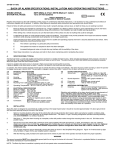
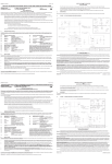
FIGURE 1 - OUTLINE DRAWING AND WIRING DIAGRAM
MANUFACTURER LIMITED WARRANTY AND
LIMITATION OF LIABILITY
Manufacturer warrants that on the Date of Purchase this Product will conform to Manufacturer's published specifications for the product, which are available from Manufacturer on request,
and Manufacturer warrants that the product is free from defects in materials and workmanship. This Limited Warranty extends for the life of the product from the date of manufacture. Manufacturer will,
at its option, repair or replace any product found by Manufacturer to be defective and subject to this Limited Warranty.
This Limited Warranty does not apply to parts or products that are misused; abused; modified; damaged by accident, fire or other hazard; improperly installed or operated; or not maintained
in accordance with the maintenance procedures set forth in Manufacturer's Installation and Operating Instructions.
To obtain warranty service, you must ship the product(s) to the specified Manufacturer location. You must fill out the warranty claim form and include the form with the product. You must
prepay shipping charges and use the original shipping container or equivalent.
EXCLUSION OF OTHER WARRANTIES: MANUFACTURER MAKES NO OTHER WARRANTIES, EXPRESSED, IMPLIED OR STATUTORY. THE IMPLIED WARRANTIES
FOR MERCHANTABILITY OR FITNESS FOR A PARTICULAR PURPOSE ARE HEREBY EXCLUDED AND SHALL NOT APPLY TO THE PRODUCT. BUYER'S SOLE AND
EXCLUSIVE REMEDY IN CONTRACT, TORT OR UNDER ANY OTHER THEORY AGAINST MANUFACTURER RESPECTING THE PRODUCT AND ITS USE SHALL BE
THE REPLACEMENT OR REPAIR OF THE PRODUCT AS DESCRIBED ABOVE.
LIMITATION OF LIABILITY: IN THE EVENT OF LIABILITY FOR DAMAGES ARISING OUT OF THIS LIMITED WARRANTY OR ANY OTHER CLAIM RELATED TO
MANUFACTURER'S PRODUCTS, MANUFACTURER'S LIABILITY FOR DAMAGES SHALL BE LIMITED TO THE AMOUNT PAID FOR THE PRODUCT AT THE TIME OF
ORIGINAL PURCHASE. IN NO EVENT SHALL MANUFACTURER BE LIABLE FOR LOST PROFITS, THE COST OF SUBSTITUTE EQUIPMENT OR LABOR, PROPERTY
DAMAGE, OR OTHER SPECIAL, CONSEQUENTIAL OR INCIDENTAL DAMAGES BASED UPON ANY CLAIM FOR BREACH OF CONTRACT, NEGLIGENCE OR OTHER
CLAIM, EVEN IF MANUFACTURER OR A MANUFACTURER'S REPRESENTATIVE HAS BEEN ADVISED OF THE POSSIBILITY OF SUCH DAMAGES. Manufacturer shall
have no further obligation or liability with respect to the product or its sale, operation and use, and Manufacturer neither assumes nor authorizes the assumption of any other obligation or liability in
connection with such product.
This Limited Warranty gives you specific legal rights, and you may also have other legal rights which vary from state to state. Some states do not allow the exclusion or limitation of
incidental or consequential damages, so the above exclusion or limitation may not apply to you.
Any oral statements or representations about the product which may have been made by salesmen or Manufacturer representatives do not constitute warranties. This Limited Warranty may
not be amended, modified or enlarged, except by a written agreement signed by an authorized official of Manufacturer which expressly refers to this Limited Warranty.
Sheet 2 of 2
371-230-1A 10/04