1
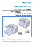
Model No. KV-S7065C
These instructions contain information on operating the scanner. Before reading these
instructions, please read the installation manual enclosed with this unit.
Please carefully read these instructions, the enclosed installation manual and maintenance
manual. Keep all documentation in a safe place for future reference.
Keep the CD-ROM in the protective case. Do not expose the CD-ROM to direct sunlight or
extreme heat and do not scratch or smudge the surface of the CD-ROM.
Thank you for purchasing a Panasonic “High Speed Color Scanner.”
≥ Panasonic supports your imaging needs with a reliable and easy to use document scanner.
≥ Panasonic has developed Panasonic Image Enhancement Technology to improve the quality of your scanned
images even beyond the quality of your original document.
∫ System requirements
When using the scanner, the required host computer conditions are as follows.
SCSI Connection
USB Connection
CPU
Minimum
Recommended
Pentium III, 1 GHz
Pentium 4, 2 GHz or higher
Memory
Minimum
Recommended
256 MB
512 MB or higher
OS
Windows® 98 / Windows NT ® 4.0 /
Windows® 2000 / Windows® Me / Windows® XP
Display
1024k768 dots or more, 65536 colors or more
Interface
SCSI III
Recommended SCSI board
Adaptec SCSI 2930U / 2940U / 29160N /19160
Windows® 98 / Windows® 2000 /
Windows® Me / Windows® XP
USB 2.0
§ 1 GB or more free space is required in the HDD.
§ Color images larger than A3 size cannot be scanned in 600 dpi on Windows 98 or Windows Me. A large size
color image may not be scanned in high resolution depending on a computer system or application.
§ The scanning speed differs depending on the host computer operating environment or application.
§ If you connect the scanner to a USB hub, it is not guaranteed to work.
§ When using the scanner with other SCSI devices connected by daisy chain connection, it is not guaranteed to
work.
Important
≥ Do not duplicate currency.
≥ Do not duplicate copyrighted material or the work of others except for the purpose of private use.
≥ Do not duplicate any kind of certificates, licenses, passports, official or private documents, and the like.
As an ENERGY STAR® Partner, Panasonic has determined that this product meets the
ENERGY STAR® guidelines for energy efficiency.
(ENERGY STAR and the ENERGY STAR certification mark are registered US marks.)
≥ Microsoft®, Windows® and Windows NT® are either registered trademarks or trademarks of Microsoft Corporation
in the United States and/or other countries.
Windows® 98 is Microsoft® Windows® 98 operating system.
Windows® Me is Microsoft® Windows® Me operating system.
Windows NT® is Microsoft® Windows NT® operating system.
Windows® 2000 is Microsoft® Windows® 2000 operating system.
Windows® XP is Microsoft® Windows® XP operating system.
≥ ISIS® is a registered trademark of Pixel Translations, a division of Captiva Software Corporation.
≥ Pentium® is a trademark or registered trademark of Intel Corporation or its subsidiaries in the United States and
other countries.
≥ Adaptec is a registered trademark of Adaptec, Inc.
≥ Each company’s name or company product name is each company’s trademark or registered trademark.
The information given in these Operating Instructions is subject to change without notice.
2
Table of Contents
Page
Notice . . . . . . . . . . . . . . . . . . . . . . . . . . . . . . . . . . . . . . . . . . . . . . . 4
Before
You Start
Precautions . . . . . . . . . . . . . . . . . . . . . . . . . . . . . . . . . . . . . . . . . . . 7
Component Identification . . . . . . . . . . . . . . . . . . . . . . . . . . . . . . 10
≥ Power turn-on sequence . . . . . . . . . . . . . . . . . . . . . . . . . . . . . . . . . . . . . . . . 12
≥ About LED . . . . . . . . . . . . . . . . . . . . . . . . . . . . . . . . . . . . . . . . . . . . . . . . . . . 12
≥ About the SCSI setting (Not required for USB connection) . . . . . . . . . . . . . . 13
Loading Documents on the ADF. . . . . . . . . . . . . . . . . . . . . . . . . 14
≥ When scanning multiple sheets . . . . . . . . . . . . . . . . . . . . . . . . . . . . . . . . . . . 15
Feeding a Document Manually . . . . . . . . . . . . . . . . . . . . . . . . . . 18
Loading Documents on the Flatbed . . . . . . . . . . . . . . . . . . . . . . 19
Operation
≥ When scanning with the flatbed . . . . . . . . . . . . . . . . . . . . . . . . . . . . . . . . . . . 19
≥ Scanning thick documents . . . . . . . . . . . . . . . . . . . . . . . . . . . . . . . . . . . . . . . 20
≥ When scanning with the flatbed repeatedly . . . . . . . . . . . . . . . . . . . . . . . . . . 20
Others . . . . . . . . . . . . . . . . . . . . . . . . . . . . . . . . . . . . . . . . . . . . . . 21
≥ How to use the control sheet . . . . . . . . . . . . . . . . . . . . . . . . . . . . . . . . . . . . . 21
Changing the Reference Plate Setting . . . . . . . . . . . . . . . . . . . . 22
≥ ADF reference plate setting . . . . . . . . . . . . . . . . . . . . . . . . . . . . . . . . . . . . . . 22
≥ Flatbed sheet setting . . . . . . . . . . . . . . . . . . . . . . . . . . . . . . . . . . . . . . . . . . . 23
Clearing Paper Jams . . . . . . . . . . . . . . . . . . . . . . . . . . . . . . . . . . 24
≥ Removing paper jams from the document feeder . . . . . . . . . . . . . . . . . . . . . 24
≥ Removing paper jams from the exit path . . . . . . . . . . . . . . . . . . . . . . . . . . . . 25
Cleaning the Unit . . . . . . . . . . . . . . . . . . . . . . . . . . . . . . . . . . . . . 26
Care
and
Maintenance
≥ Outside of the scanner . . . . . . . . . . . . . . . . . . . . . . . . . . . . . . . . . . . . . . . . . .
≥ Inside the scanner . . . . . . . . . . . . . . . . . . . . . . . . . . . . . . . . . . . . . . . . . . . . .
≥ Cleaning the paper feed roller, separation roller, and retard roller. . . . . . . . .
≥ Cleaning the drive rollers and free rollers . . . . . . . . . . . . . . . . . . . . . . . . . . .
≥ Cleaning the drive rollers, free rollers, and exit roller. . . . . . . . . . . . . . . . . . .
≥ Cleaning the reference plates and ADF glasses . . . . . . . . . . . . . . . . . . . . . .
≥ Cleaning the paper and waiting sensors, double feed detector . . . . . . . . . . .
≥ Cleaning the starting, skew and ending sensors . . . . . . . . . . . . . . . . . . . . . .
≥ Cleaning the flatbed glass and document cover detector . . . . . . . . . . . . . . .
26
26
27
29
30
31
32
33
34
Replacing Consumable Roller Modules . . . . . . . . . . . . . . . . . . . 35
≥ Replacing paper feed roller modules . . . . . . . . . . . . . . . . . . . . . . . . . . . . . . . 35
≥ Replacing Retard Roller . . . . . . . . . . . . . . . . . . . . . . . . . . . . . . . . . . . . . . . . . 37
Shading Adjustment. . . . . . . . . . . . . . . . . . . . . . . . . . . . . . . . . . . 39
Repacking Instructions . . . . . . . . . . . . . . . . . . . . . . . . . . . . . . . . 40
Appendix
Specifications . . . . . . . . . . . . . . . . . . . . . . . . . . . . . . . . . . . . . . . . 41
Troubleshooting . . . . . . . . . . . . . . . . . . . . . . . . . . . . . . . . . . . . . . 42
Index . . . . . . . . . . . . . . . . . . . . . . . . . . . . . . . . . . . . . . . . . . . . . . . 44
3
Notice
Federal Communications Commission Requirements
(For United States only)
Note: This equipment has been tested and found to comply with the limits for a Class A digital device, pursuant to
part 15 of the FCC Rules. These limits are designed to provide reasonable protection against harmful
interference when the equipment is operated in a commercial environment. This equipment generates, uses,
and can radiate radio frequency energy and, if not installed and used in accordance with the instruction
manual, may cause harmful interference to radio communications. Operation of this equipment in a
residential area is likely to cause harmful interference in which case the user will be required to correct the
interference at his own expense.
FCC Warning: To assure continued FCC compliance, the user must use only shielded interface cable and the
provided power supply cord. Also, any unauthorized changes or modifications to this equipment would void the
user’s authority to operate this device.
English
WARNING:
TO PREVENT FIRE OR SHOCK HAZARD, DO NOT EXPOSE THIS PRODUCT TO RAIN OR
ANY TYPE OF MOISTURE.
THE SOCKET-OUTLET MUST BE NEAR THIS EQUIPMENT AND MUST BE EASILY
ACCESSIBLE.
The product should be used only with a power cord that is supplied by the manufacturer.
Power Source
WARNING
≥ (220-240 V equipment)
A certified power supply cord has to be used with this equipment. The relevant national installation and/or
equipment regulations shall be considered. A certified power supply cord not lighter than ordinary polyvinyl
chloride flexible cord according to IEC 60227 (designation H05VV-F 3G 1.0 mm2).
4
Notice
(For United Kingdom only)
For your safety please read the following text carefully.
This appliance is supplied with a moulded three pin mains plug for your safety and convenience.
A 5 amp. fuse is fitted in this plug. Should the fuse need to be replaced, please ensure that the replacement fuse has
a rating of 5 amps. and that it is approved by ASTA or BSI to BS1362. Check for the ASTA mark
or the BSI mark
on the body of the fuse. If the plug contains a removable fuse cover you must ensure that it is refitted when the
fuse is replaced. If you lose the fuse cover the plug must not be used until a replacement cover is obtained. A
replacement fuse cover can be purchased from your local Panasonic Dealer.
If the fitted moulded plug is unsuitable for the socket outlet in your home then the fuse should be removed and the
plug cut off and disposed of safely.
There is danger of severe electrical shock if the cut off plug is inserted into any 13 amp. socket.
If a new plug is to be fitted please observe the wiring code as shown below. If in any doubt please consult a qualified
electrician.
WARNING: This appliance must be earthed.
IMPORTANT: The wires in this mains lead are coloured in accordance with the following code.
Green-and-Yellow
: Earth
Blue
: Neutral
Brown
: Live
As the colours of the wire in the mains lead of this appliance may not correspond with the coloured markings
identifying the terminals in your plug, proceed as follows.
The wire which is coloured Green-and-Yellow must be connected to the terminal in the plug which is marked with the
letter E or by the Earth symbol
or coloured Green-and-Yellow.
The wire which is coloured Blue must be connected to the terminal in the plug which is marked with the letter N or
coloured Black.
The wire which is coloured Brown must be connected to the terminal in the plug which is marked with the letter L or
coloured Red.
How to replace the fuse :
Open the fuse compartment with a screwdriver and replace
the fuse.
5
Notice
Roller cleaning paper precautions
Before using the roller cleaning paper, please read these instructions completely. Keep these instructions for future
reference.
English
WARNING
•
•
•
•
•
•
Do not drink or inhale the roller cleaning paper fluid including isopropyl alcohol.
The roller cleaning paper may be harmful to sensitive skin. Please use protective gloves.
Do not use the roller cleaning paper near a heater or open flame.
Do not store the roller cleaning paper in direct sunlight or in a place with temperature over 40 oC (104 oF).
Only use the roller cleaning paper to clean the rollers and scanning area.
If you need more information about the roller cleaning paper, please refer to the Material Safety Data Sheet
(MSDS).
• Please ask your Panasonic sales company about obtaining the Material Safety Data Sheet.
KEEP AWAY FROM FIRE.
6
Precautions
The following precautions are recommended to extend the life of the unit:
Prior to scanning, remove all staples and
paper clips from pages.
Do not place floppy disks or any items
containing magnetic data strips on the
flatbed.
—Magnets are located in the flatbed
cover (flatbed sheet) and may damage
data stored on floppy disks and magnetic strips.
Do not place any liquids near the
unit.
Do not place books, paper, or other
items on the unit.
Do not place the unit in an area
where there is a lot of smoke, dust,
chemical fumes or vibration.
Do not place the unit on an uneven
or unstable surface.
Do not disassemble the unit.
This will void your warranty.
—Accidental spillage of liquid into
the unit may cause severe damage. If this occurs, turn the unit
off, unplug the power cord and
call for service.
Do not leave the power cord
plugged into the AC outlet if the unit
will not be used for an extended
period.
It is recommended that at least two people carry the
scanner by holding four hollows on the front and rear
sides.
Do not look directly at the light.
(You may damage your eyes.)
Hollows
≥ Special care should be taken to protect the unit if it is used in a less than optimum environment, such as a dusty or
sandy area.
7
Precautions
Operating Environment
Do not place the unit in direct sunlight or in a cold
draft.
Hot
Cold
Do not operate or place the unit in a vertical position.
Do not place the unit near a heating appliance or an
air conditioning vent. Do not place the unit in a room
with extremely high or low humidity.
Do not place the unit near other appliances which generate large electrical noise.
Do not place the unit on a carpet. (Static electricity
can cause the unit to malfunction.)
Do not drink or inhale the included roller cleaning paper
fluid.
The roller cleaning paper may be harmful to sensitive
skin. Please use protective gloves.
Do not use the roller cleaning paper near a heater or
open flame. This may cause a fire.
≥Power Source
≥ Use a voltage level that does not vary more than d10% from the voltage level marked on the nameplate
(located on the back side of the scanner).
≥ Do not use an extension cord.
≥ This scanner should be connected to a grounded outlet.
≥ Do not use a line conditioner, transient suppressor or surge protector.
8
Precautions
∫ CD-ROM
To prevent the CD-ROMs from accidental damages:
Do not touch or write on the surface
of the disc.
Do not leave the disc out of its
protective case.
Do not place heavy objects on the
disc case or drop the case.
To clean the disc, hold the disc by
its edges and wipe it from the
center to the edges with a dry, soft
cloth.
Do not leave the disc in direct
sunlight or near heat sources.
9
Component Identification
Document guide
Hopper
ADF door
Hopper tray
Hopper extension
tray
Back stopper
Exit stopper
ADF door release
Manual feed selector
Exit tray
Power indicator
When the power is turned on, the green
indicator lights.
When an error occurs, the indicator will
change to red, and light steadily or flash.
Power switch
Document cover
STOP/START button
Used to stop or start scanning a document.
Exit door
Top cover
Imprinter door
AC inlet
Power cord
SCSI connector
USB connector
FAN exhaust vent
10
Component Identification
Flatbed sheet
Flatbed glass
Exit door release
ADF glass (B)
Reference plate (F)
Reference
plate (B)
ADF glass (F)
11
Component Identification
∫ Power turn-on sequence
1
Turn on the power of the scanner.
2
Turn on the power of the host
computer after scanner’s LED stays
green.
≥ The LED will now light.
≥ In case of the USB connection, the host
computer recognizes the scanner automatically when the scanner is powered on
even after the host computer is powered
on.
LED
Power switch
∫ About LED
LED indicates the status of the scanner as follows:
LED light
Status
Green
Ready to scan or scanning
Green (flashing)
Sleep mode
Orange
Ready to scan or scanning with warning *1
Orange (flashing)
Initializing
Sleeping with warning *1
Red
An error occurred *2
*1: The rollers need to be cleaned or replaced.
Refer to Maintenance Manual or Operating Instructions (CD-ROM) for the way of cleaning or replacing the
rollers.
*1, *2: Check the status of the scanner using the User Utility.
The User Utility is included in the CD-ROM.
12
Component Identification
∫ About the SCSI setting (Not required for USB connection)
When connecting the scanner to a SCSI chain using a SCSI cable, perform the SCSI ID setting correctly.
The scanner is provided with a DIP switch for the SCSI ID No. setting.
SCSI ID Setting
Switch
ID No.
Remarks
#2
#1
#0
0
OFF
OFF
OFF
1
OFF
OFF
ON
2
OFF
ON
OFF
3
OFF
ON
ON
4
ON
OFF
OFF
5
ON
OFF
ON
6
ON
ON
OFF
7
ON
ON
ON
Default setting
13
Loading Documents on the ADF
ADF (Auto Document Feeder) enables multiple sheet scanning.
Acceptable documents
Document size:
48~297 mm (1.9~11.7 in.)
70~635 mm (2.75~25 in.)
Paper thickness: 40–127 g/m2
Maximum number of sheets loadable on the hopper tray
The height of the document should not exceed the limit mark on the document guide.
g/m2
40
52
64
75
80
90
104
127
lb.
11
14
17
20
21
24
28
34
320
260
200
170
160
140
120
100
Maximum number of sheets
Recommendable paper: Plain paper
The following types of documents may not be scanned properly.
≥ Broken or notched documents
≥ Curled, wrinkled or folded documents
Curl:
Feeding direction
Less than
5 mm
Fold:
Feeding direction
Less than
5 mm
≥ Perforated or punched documents
≥ Not rectangular or irregularly shaped documents
≥ Tracing paper
≥ Thermal paper
When scanning is not performed properly, try the following methods:
≥ Set the feed speed to “Slow”.
≥ Scan the documents by manual feeding.
≥ Scan the documents with the flatbed.
The following types of documents may cause frequent jams and double feeding.
≥ Extremely smooth or shiny paper or paper that is highly textured
≥ Paper with carbon
≥ Carbonless paper
If a paper jam or double feeding occurs, clean the rollers.
When a jam occurs at the document feeder, reduce the number of sheets loaded on the hopper to about 20.
Types of documents to avoid
≥ OHP sheets, other plastic films, cloths, or metallic sheets.
≥ Paper with irregularities such as tabs, staples, paste, etc.
≥ Documents with wet ink
≥ Thick or irregular documents such as envelopes, documents that are glued together, etc.
Be sure to remove the document from the exit tray after it is scanned.
When scanning different size documents, scanned sheets may need to be reordered for optimum performance.
Thick, thin or important document should be scanned by the flatbed or fed manually one sheet at a time.
14
Loading Documents on the ADF
∫ When scanning multiple sheets
Cautions:
≥ Please remove any staples from the document before scanning.
≥ Glued or curled documents may cause a paper jam or damage the unit, so please scan using the flatbed.
1
Documents that have been stapled
together or stacked together (as in a
file folder) will need to be separated.
Prior to scanning, remove, all staples and paper clips
from pages.
1 Fan the stack of documents to
separate all the edges.
2 Hold both ends and bend the
documents as shown in the
illustration.
3 To flatten the documents, hold firmly
and pull them apart as shown in the
illustration.
Repeat these steps as necessary.
2
Carefully align the documents.
3
Adjust the document guides slightly
larger than the actual size of the
documents.
1
2
3
Document guide
15
Loading Documents on the ADF
4
Set the manual feed selector to
“AUTO”.
Manual feed
selector
5
When using long paper, pull out the
hopper extension tray from the hopper.
Then raise and adjust the exit stopper
to the position a little longer than the
actual length of the document.
Hopper
Exit stopper
16
Hopper extension
tray
Loading Documents on the ADF
6
Place the documents on the hopper
Portrait
with the side to be scanned facing up.
Then push them in the direction of the
arrow until they stop.
≥ The amount of documents should not
exceed the limit mark on the document
guide. This may cause a paper jam or
skew.
Fill indicator
(Limit mark)
Landscape
7
Adjust the document guide to the size
of the document to be scanned.
Adjust the exit stopper to the size of the
document to be output.
Document guide
≥ When scanning the document with the
length between 420 mm (A3 size) or 432
mm (17 in.) and 635 mm (25 in.) close the
exit stopper.
Exit stopper
17
Feeding a Document Manually
When scanning a document one page at a time with the ADF, set the manual feed selector to “MANUAL” and the
pages can be scanned one page at a time.
Cautions:
≥ Please remove any staples from the document before scanning.
≥ Glued or curled documents may cause a paper jam or damage the unit, so please scan using the flatbed.
1
Set the manual feed selector to
“MANUAL”.
Manual feed
selector
2
Match the document guide with the
size of the document.
3
Insert the document into the paper slot
one page at a time.
4
Adjust the document guide with the
size of the document when the
document guide does not suit the size
of the document. Adjust the exit
stopper to the size of the document to
be output.
18
Document guide
Paper slot
Loading Documents on the Flatbed
One sheet or an entire book document can be scanned on the document glass.
Scanning documents in this way is known as “scanning with the flatbed”.
Caution
≥ Do not place floppy disks or any items containing magnetic data strips on the flatbed. Magnets are located in the
flatbed cover (flatbed sheet) and may damage data stored on floppy disks and magnetic strips.
∫ When scanning with the flatbed
1
Raise the hopper tray.
2
Open the document cover.
Document cover
Hopper tray
3
Place the scanning side of the
document face down on top of the
flatbed glass towards the upper left
corner.
Standard
mark
≥ If the document is bent or folded,
straighten it.
4
Match the shorter side of the document
with the left edge of the flatbed glass.
5
Match the longer side of the document
with the standard mark.
≥ If the document is slanted, it will not be
scanned properly.
Document
Standard mark
Longer side
Shorter side
Document
Flatbed glass
19
Loading Documents on the Flatbed
6
Close the document cover gently.
≥ If the document cover is slammed, the
document will move and may not be
scanned properly.
≥ Do not open or press down on the document cover during scanning.
≥ Do not look directly at the light.
(You may damage your eyes.)
≥ Be sure to close the document cover
before use.
≥ After scanning, open the document cover
and remove the document.
∫ Scanning thick documents
When scanning thick documents such as a book, please note the following items:
≥ Please note that areas of the document which are not touching the flatbed glass will not be scanned properly.
≥ If the document moves during scanning, please note that it will not be scanned properly.
∫ When scanning with the flatbed repeatedly
≥ Keep the hopper tray raised, open and close the document cover only.
20
Others
∫ How to use the control sheet
Documents
A
If the control sheet is used, the documents
behind the control sheet are scanned in
accordance with the code on the control
sheet regardless of scanning condition that
is selected previously.
Control sheet
≥ Multiple control sheets can be used.
≥ When using a control sheet, the application
software required depends on the control
sheet.
≥ Print out control sheets from the provided CDROM.
Documents
B
Cautions:
Code
≥ Use the same size control sheet as the
scanning document.
≥ When printing the control sheet, if the pattern
falls in the area from the top side of the
document to 25 mm, adjust the printer.
Also, copy the control sheet so that the pattern
lies in the center of the copy.
≥ Be careful not to get the control sheet dirty.
Do not fold or crease the control sheet.
Scanning will not be performed properly.
21
Changing the Reference Plate Setting
You can choose a background color to be scanned from white (black) to black (white). The scanner comes from factory set to black. The reference plate (B), reference plate (F) and flatbed sheet setting must be changed simultaneously. Anytime the background color is changed from its previous setting, the shading adjustment must be
performed. Please refer to page 39 for more information regarding the shading adjustment.
∫ ADF reference plate setting
1
Turn off the scanner.
2
Pull the exit door release to open the
exit door.
3
Using your finger, turn the reference
plate (B) over.
≥ Confirm that the reference plate has
changed and is locked in its proper position.
4
Exit door release
ADF glass (F)
Reference plate (B)
Using your finger, turn the reference
plate (F) over.
≥ Confirm that the reference plate has
changed and is locked in its proper position.
Reference plate (F)
ADF glass
(B)
22
Changing the Reference Plate Setting
5
Close the exit door slowly until it clicks
into place.
∫ Flatbed sheet setting
1
Turn off the scanner.
2
3
Fold the hopper tray in the direction of
the arrow.
4
Turn the flatbed sheet over.
Document cover
Hopper tray
Open the document cover.
≥ The flatbed sheet is attached to the document cover with magnets.
≥ Set the flatbed sheet to the left.
Flatbed sheet
23
Clearing Paper Jams
Torn documents, thin documents or documents that are creased on the top edge may cause paper jams. If a paper
jam occurs, remove the jammed sheet according to the following procedure.
∫ Removing paper jams from the document feeder
the ADF door release to open the
1 Push
ADF door.
ADF door
ADF door release
the jammed document towards the
2 Pull
document feeder.
ADF door
≥ When the jammed paper cannot be
removed, remove it from the exit path.
Refer to page 25.
≥ When only the bottom end of jammed
paper is visible, open the exit door while
leaving the ADF door open to remove the
jammed paper. Pulling the jammed paper
with the ADF door closed may damage
the document.
3 Close the ADF door.
≥ When you close the ADF door, close it
securely until it is locked.
24
ADF door
Clearing Paper Jams
∫ Removing paper jams from the exit path
the exit stopper and raise the hop1 Pull
per tray.
Hopper tray
Exit stopper
the exit door release, open the exit
2 Pull
door and pull the jammed document.
≥ When the jammed paper cannot be
removed, remove it from the document
feeder. Refer to page 24.
Exit door release
Exit door
3 Close the exit door.
≥ When you close the exit door, close it
securely until it is locked.
25
Cleaning the Unit
∫ Outside of the scanner
Clean the unit at least once a month.
1
Turn the power off.
2 Clean the cover with a soft cloth.
≥ The ADF insertion and exit slots get dirty
easily, therefore, proper cleaning is
required.
dirt and dust from the fan
3 Remove
exhaust vent with a brush.
: Off position
∫ Inside the scanner
Clean the unit at least once a week or when 20,000 sheets have been scanned, whichever comes first.
≥ Clean the rollers, sensors and double feed detector if paper jamming or multiple-sheet feeding occurs
frequently. (Refer to pages 27–33.)
≥ Clean the ADF glass, reference plate when black or white lines appear on the scanned images.
(Refer to page 31.)
≥ Clean the flatbed glass and document cover detector. (Refer to page 34.)
≥ If the documents you scan are dirty, then the scanner components will also become dirty.
To maintain proper scanning, clean the scanner components frequently.
≥ When scanning with the flatbed and black dots or white patches occurs, open the document cover, and clean
the flatbed glass and flatbed sheet using the accessory roller cleaning paper.
Roller cleaning paper
Open the bag on the dotted line and take out
the roller cleaning paper.
≥ If the roller cleaning paper bag is left opened for
a long period of time before using it, the alcohol
will evaporate. Please use the roller cleaning
paper immediately after opening the bag.
Dotted line
§ The roller cleaning paper (Model No. KV-SS03) is available from the dealer where you
purchased your scanner.
For supplies and accessories: Call 1-800-346-4768 (U.S.A. only) or your dealer.
26
Cleaning the Unit
∫ Cleaning the paper feed roller, separation roller, and retard roller
1
Turn the power off.
ADF door
the ADF door release to open the
2 Push
ADF door.
ADF door release
the roller cleaning paper (KV3 Use
SS03) to remove the dirt from the
Separation roller
Paper feed roller
surfaces of the paper feed roller and
separation roller.
Note:
≥ When wiping off the dirt on the roller
surfaces, hold the rollers to prevent them
from rotating, and wipe the roller all the
way around them proceeding from one
end to the other in the direction of the
arrows shown in the figure.
the retard cover in the direction
4 Open
of the arrow shown in the figure by
using the indent on the back side.
Retard roller
Indent
Retard cover
27
Cleaning the Unit
the roller cleaning paper (KV5 Use
SS03) to remove the dirt from the
Retard roller
surface of the retard roller.
Note:
≥ When wiping off the dirt on the roller
surfaces, hold the rollers to prevent them
from rotating, and wipe the roller all the
way around them proceeding from one
end to the other in the direction of the
arrows shown in the figure.
the retard cover in the direction
6 Close
of the arrow shown in the figure.
7 Close the ADF door.
≥ When you close the ADF door, close it
securely until the door is locked.
the roller cleaning counter with
8 Clear
User Utility.
≥ After cleaning the above rollers, click
[Clear Counter] button for [After Clean
Roller] with User Utility.
28
Retard roller
Retard cover
ADF door
Cleaning the Unit
∫ Cleaning the drive rollers and free rollers
1 Turn the power off.
the ADF door release to open the
2 Push
ADF door.
the roller cleaning paper (KV3 Use
SS03) to remove the dirt from the
Drive rollers
Drive rollers
surfaces of the 4 drive rollers.
≥ When wiping off the dirt on the roller
surfaces, hold the rollers to prevent them
from rotating, and wipe the roller all the
way around them proceeding from one
end to the other in the direction of the
arrows shown in the figure.
the roller cleaning paper (KV4 Use
SS03) to remove the dirt from the
Free rollers
surfaces of the 4 free rollers.
≥ When wiping off the dirt on the roller
surfaces, hold the rollers to prevent them
from rotating, and wipe the roller all the
way around them proceeding from one
end to the other in the direction of the
arrows shown in the figure.
5 Close the ADF door.
≥ When you close the ADF door, close it
securely until it is locked.
29
Cleaning the Unit
∫ Cleaning the drive rollers, free rollers, and exit rollers
1 Turn off the scanner.
the exit door release to open the
2 Pull
exit door.
the roller cleaning paper (KV3 Use
SS03) to remove the dirt from the
surfaces of the 4 drive rollers and the 2
exit rollers.
≥ When wiping off the dirt on the roller
surfaces, hold the rollers to prevent them
from rotating, and wipe the roller all the
way around them proceeding from one
end to the other in the direction of the
arrows shown in the figure.
the roller cleaning paper (KV4 Use
SS03) to remove the dirt from the
surfaces of the 6 free rollers.
≥ When wiping off the dirt on the roller
surfaces, hold the rollers to prevent them
from rotating, and wipe the roller all the
way around them proceeding from one
end to the other in the direction of the
arrows shown in the figure.
30
Exit door release
Exit rollers
Drive rollers
Drive rollers
Free rollers
Cleaning the Unit
5 Close the exit door.
≥ When you close the exit door, close it
securely until it is locked.
∫ Cleaning the reference plates and ADF glasses
1 Turn off the scanner.
the exit door release to open the
2 Pull
exit door.
the ADF glass (F) and reference
3 Clean
plate (B) with the roller cleaning paper
ADF glass (F)
Reference plate (B)
(KV-SS03).
the ADF glass (B) and reference
4 Clean
plate (F) with the roller cleaning paper
(KV-SS03).
5
Reference plate (F)
Close the exit door.
≥ When you close the exit door, close it
securely until it is locked.
ADF glass
(B)
31
Cleaning the Unit
∫ Cleaning the paper and waiting sensors, double feed detector
How to clean sensors (detectors) and reflectors.
Remove the brush from the accessory blower and blow off the dirt with the blower.
Blower
Sensor or detector
1 Turn off the scanner.
the ADF door release to open the
2 Push
ADF door.
off the dirt on the surface of the
3 Blow
paper sensor and waiting sensor with
Reflector sheet
for waiting sensor
Paper sensor
Waiting sensor
an accessory blower.
also blow off the dirt on the
4 And
surface of the reflector sheet for the
waiting sensor with the accessory
blower.
off the dirt from the double feed
5 Blow
detector (G) and double feed detector
(R) with the accessory blower.
6 Close the ADF door.
≥ When you close the ADF door, close it
securely until it is locked.
32
Double feed detector (G)
Double feed detector (R)
Cleaning the Unit
∫ Cleaning the starting, skew and ending sensors
How to clean sensors (detectors) and reflectors.
Remove the brush from the accessory blower and blow off the dirt with the blower.
Blower
Sensor or detector
1 Turn off the scanner.
the exit door release to open the
2 Pull
exit door.
off the dirt on the surface of the
3 Blow
starting, skew (L), skew (R), and
Ending sensor
Skew (R) sensor
ending sensors with the accessory
blower.
Skew (L) sensor
blow off the dirt from the reflector
4 And
sheets for the starting, skew (L), skew
(R), and ending sensors with the
blower.
5 Close the exit door.
≥ When you close the exit door, close it
securely until it is locked.
Starting sensor
Reflector sheet for
skew (R) sensor
Reflector sheet for
ending sensor
Reflector sheet for
starting sensor
Reflector sheet
for skew (L)
sensor
33
Cleaning the Unit
∫ Cleaning the flatbed glass and document cover detector
1 Turn off the scanner.
the hopper tray in the direction of
2 Fold
the arrow.
3 Open the document cover.
Document cover
Hopper tray
up the surface of flatbed glass
4 Clean
with the roller cleaning paper (KV-
Flatbed sheet
SS03) to remove the dirt.
(Also clean up the surface of the
flatbed sheet, as required.)
off the dirt from the document
5 Blow
cover detector.
the document cover and put
6 Close
back the hopper tray to the original
position.
Flatbed glass
Document cover detector
How to clean sensors (detectors) and reflectors.
Remove the brush from the accessory blower and blow off the dirt with the blower.
Blower
Sensor or detector
34
Replacing Consumable Roller Modules
∫ Replacing paper feed roller modules
Recommended change : 300,000 scans
1
Turn the power off.
ADF door
the ADF door release to open the
2 Push
ADF door.
ADF door release
down the paper feed roller module
3 Pull
in the direction of the arrow.
the paper feed roller module
4 Remove
as shown on the figure.
the optional roller exchange kit
5 Open
(KV-SS015), and take out the new
paper feed roller module.
35
Replacing Consumable Roller Modules
the
6 Install
module.
new paper feed roller
up the new paper feed roller
7 Push
module in the direction of the arrow, so
that it is locked by the magnets on both
sides.
8 Close the ADF door.
≥ When you close the ADF door, close it
securely until it is locked.
36
Replacing Consumable Roller Modules
∫ Replacing Retard Roller
1 Turn the power off.
the ADF door release to open the
2 Push
ADF door.
ADF door
ADF door release
the retard cover in the direction
3 Open
of the arrow shown in the figure by
Retard roller
Indent
Retard cover
using the indent on the back side.
the retard roller, pulling up the
4 Remove
shaft in the direction of the arrow.
out the new retard roller in the
5 Take
optional roller exchange kit (KVSS015).
37
Replacing Consumable Roller Modules
the new retard roller by matching
6 Install
the groove of its shaft with the groove
of the metal holder.
7 Close the retard cover.
8 Close the ADF door.
≥ When you close the ADF door, close it
securely until it is locked.
the roller replacing counter with
9 Clear
User Utility.
≥ Click [Clear Counter] button for [After
Replace Roller] with User Utility.
38
Groove
Shading Adjustment
¥What is the purpose of the shading adjustment?
The process whereby the variations in the distribution of the lamp’s light quantity are transformed into a fixed output
within the scanning range is known as shading adjustment. It can be carried out by means of the User Utility using
the special shading paper which is provided with this scanner.
¥When shading adjustment is required
Proceed with the compensation when the colors in some parts of the scanned images differ in the extreme, or when
the image quality fails to be improved even after the inside the scanner is cleaned.
¥Before proceeding with the shading adjustment
Before proceeding, be absolutely sure to thoroughly clean the ADF glass (F) area, ADF glass (B) area, reference
plate (F) and reference plate (B) as well as the transport path and drive rollers of the scanning unit.
If the shading adjustment is carried out while these parts are still dirty, it will not be possible to eliminate the lines that
form on the scanned images.
¥Shading adjustment procedure
1. Start the User Utility.
2. Click “User Shading” on the main menu, and operate as the image display dictates. For further details, refer to
section 4.6 in the User Utility Reference Manual.
¥Caution
If the scanned images are still lined after the shading adjustment has been performed and if these lines are not eliminated even after the ADF glass areas have been cleaned, it means that the shading has not been compensated
properly. Clean the parts again, and then proceed with the shading adjustment.
39
Repacking Instructions
It is highly recommended that you keep the original carton and ALL packing materials. If you need to transport or
ship your scanner, please follow these instructions:
≥ Use the original carton and all of the original packing materials.
≥ Improper repacking of the scanner may result in a service charge to repair the unit.
≥ The scanner should be handled in the correct (horizontal) position.
Materials Required:
≥ Original scanner carton & packing materials
≥ Shipping tape and scissors
1
2
3
Turn the power switch off and disconnect your scanner from the electrical outlet and the
interface cable.
Remove the hopper tray and attach the protective sheets with tapes.
Pack the scanner.
CD-ROM
(Operating instructions)
(Driver software)
Installation manual
Maintenance manual
Roller cleaning paper (3 pieces)
Shading chart
Blower
USB2.0 cable
Hopper tray
Power cord
40
Specifications
Model No.
KV-S7065C
Item
Scanner
Scanning face
Duplex scanning
Scanning method
CIS (Contact-type color Image Sensor)
Readout
speed
Flatbed
0.704 sec (Letter, 200 dpi)
ADF
Simplex scanning:
Approx. 60 sheets/min. (Letter, fed lengthwise, 200 dpi)
Approx. 60 sheets/min. (A4, fed lengthwise, 200 dpi)
Duplex scanning:
Approx. 50 sheets/min. (Letter, fed lengthwise, 200 dpi)
Approx. 50 sheets/min. (A4, fed lengthwise, 200 dpi)
Resolution
Flatbed/ADF
Main scanning direction: 100-600 dpi (1 dpi step)
Sub-scanning direction: 100-600 dpi (1 dpi step)
The optical resolution is 600 dpi.
Tonal gradation
Binary mode, Grayscale mode (8 bit), 64-step gradation
(dither) mode, Error diffusion mode
Image control
Image emphasis, Dynamic Threshold, Automatic
separation, Invert, White level from paper
Paper
Unit
320 µsec/line
Size for Flatbed
~ 297k432 mm (11.7k17 in.)
Size for ADF
Scanning size: 48k70 mm (1.9k2.8 in.)~
297 mm (11.7 in.)k635 mm (25 in.)
Thickness for ADF
0.05 to 0.15 mm (2.0 to 5.9 mils)
Business card: Thicker than 0.15 mm (5.9 mils)
Note: 1 mil = 1/1000 in.
Weight for ADF
40 to 127 g/m2 (10.6 to 34 lbs.)
Business card: Thicker than 127 g/m2 (34 lbs.)
Hopper capacity
200 sheets [64 g/m2 (17 lbs.)]
External dimensions
(WidthkDepthkHeight)
755k508k289 mm (29.7k20k11.4 in.)
Mass (Weight)
29 kg (64 lbs.)
Power requirement
AC100–120 V 50/60 Hz
Power
consumption
Maximum
(Scanning)
1.5 A (AC100–120 V)
0.7 A (AC220–240 V)
Minimum (Standby)
0.6 A (AC100–120 V)
0.3 A (AC220–240 V)
Sleep mode
8 W (AC100–120 V)
AC220–240 V 50/60 Hz
8 W (AC220–240 V)
Operating
Environment
Operating temperature and
humidity
15 °C to 30 °C (59 °F to 86 °F), 30% to 80% RH
Storage
Environment
Storage temperature and humidity
0 °C to 35 °C (32 °F to 95 °F), 10% to 80% RH
Option
Roller exchange kit (KV-SS015), Imprinter unit (KV-SS014), Ink cartridge (KV-SS021),
Roller cleaning paper (KV-SS03)
≥ “Weight in pounds” of paper represents the weight of 500 [432k559 mm (17k22 inches)] sheets.
41
Troubleshooting
If a problem occurs while the unit is being used, check the following items and check the scanner status with the User
Utility. If the unit still malfunctions, turn it OFF, unplug the power cord and call for service.
Symptom
Possible Cause
Remedy
The power cord is not plugged in.
Insert the power plug firmly.
Problem with power supply.
Disconnect the scanner from the
electric outlet and call for service.
The scanner is not connected to the
computer correctly.
Connect the cables correctly.
The scanner is not registered
correctly.
Uninstall the scanner from the
computer.
Register the scanner hardware again.
(Refer to the Installation Manual on
pages 18 and 19.)
The computer cannot recognize the
SCSI card.
Check your computer whether the
SCSI card is installed correctly using
the device manager’s property. Refer
to the Installation Manual on page 17.
The same ID number is used for the
scanner and the other device.
Use the different SCSI ID numbers for
each devices. (See page 13.)
The scanner was turned on after the
computer was turned on.
Turn the computer OFF. Turn the
scanner ON, and then turn the
computer ON again.
The USB interface of the computer is
not installed correctly.
Check the computer whether the USB
interface of your computer is installed
correctly using the device manager’s
property.
The scanner is connected via USB
hub.
Do not connect via USB hub.
The cable without High-Seed logo is
used.
Use the cable with High-Speed logo.
Scan speed is slow at USB
connection.
The scanner is connected with USB
1.1.
Connect with USB 2.0.
The ADF does not open
when the ADF door release
is pushed.
The ADF door is not closed properly.
Push the ADF door release again after
you close the ADF door until it is
locked.
The document is not loaded
properly.
Load the document correctly.
(See page 14.)
The sensor cannot detect the
document as the edge of the document
is curled.
Flatten the document and load it again.
The LED does not light when
the power switch is turned
ON.
The computer does
recognize the scanner.
not
SCSI
connection
USB
connection
(ADF)
The document has been
loaded on the hopper tray.
But the scanner does not
start scanning.
42
Troubleshooting
Symptom
Possible Cause
(ADF)
Double feeding problems
occurs frequently or the
scanner stops loading while
scanning.
Remedy
The rollers are dirty.
Clean all of the rollers. (See page 27.)
The rollers have reached their life
expectancy.
Replace the paper feed roller module
and the retard roller module. (See
page 35 and page 37.)
The document is curled or folded.
Flatten the document and load it again
after reducing the pages.
The irregular type document is to be
scanned.
Make a copy of the document on
specified paper (see page 14) and
scan the copy.
The document has a length of less
than 70 mm (2.75 in.).
Make a copy of the document on paper
of the specified size and scan the copy.
(See page 14.)
The document guides are not adjusted
to the size of the document to be
scanned.
The document to be scanned is set
aslant on the hopper tray.
Adjust the document guides properly to
the size of the document to be
scanned.
Right and left sides of the document to
be scanned are not the same in height,
because of curl and fold.
Remove curl and fold then reduce the
amount of the document.
The document to be scanned was
loaded face down (upside down).
Load the document correctly.
(See page 17.)
The ADF glasses and flatbed glass are
dirty.
Clean the ADF glasses and flatbed
glass. (See page 31.)
The reference plate and flatbed sheet
are dirty.
Clean the reference plate and flatbed
sheet. (See page 31 and page 34.)
The ADF glass, reference plate, flatbed
glass and flatbed sheet are dirty.
Clean the ADF glass, reference plate,
flatbed glass and flatbed sheet. (See
page 31 and See page 34.)
The quantity distribution of light varies.
Adjust shading. Please refer to section
4.6 of a user utility reference manual.
The color of the scanned
document
is
extremely
different from the original
document.
The settings of the computer monitor is
wrong.
Adjust the computer monitor settings.
Dark spots or noise appear
on the scanned documents.
The ADF glass, reference plate, flatbed
glass and flatbed sheet are dirty.
Clean the ADF glass, reference plate,
flatbed glass and flatbed sheet. (See
page 31 and See page 34.)
Scanned image has moire
fringes such as stripe or
wavy pattern noise.
It is caused by printing pattern of the
document and the congeniality of the
scanning resolution.
Please use the moire reduction
function or change the resolution and
try to scan.
(ADF)
Scanned image is aslant.
(ADF)
The scanned document is
blank.
Vertical lines appear on the
scanned document.
The scanning
uneven.
density
is
43
Index
Page
Page
A
F
AC inlet . . . . . . . . . . . . . . . . . . . . . . . . . . . 10
Acceptable documents . . . . . . . . . . . . . . . 14
Accessories . . . . . . . . . . . . . . . . . . . . . . . 26
ADF door . . . . . . . . . . . . . . . . . . . 10, 24, 27
ADF door release . . . . . . . . . . . . . 10, 24, 27
ADF glass . . . . . . . . . . . . . . . . . . . . . . 11, 31
FAN exhaust vent . . . . . . . . . . . . . . . . . . 10
Fan exhaust vent . . . . . . . . . . . . . . . . . . . 26
Flatbed . . . . . . . . . . . . . . . . . . . . . 19, 23, 41
Flatbed glass . . . . . . . . . . . . . . . . 11, 26, 34
Flatbed sheet . . . . . . . . . . . . . . . . 11, 23, 34
Free rollers. . . . . . . . . . . . . . . . . . . . . 29, 30
B
H
Back stopper. . . . . . . . . . . . . . . . . . . . . . . 10
Blower. . . . . . . . . . . . . . . . . . . . . . 32, 33, 34
Hopper . . . . . . . . . . . . . . . . . . . . . . . . 10, 16
Hopper extension tray . . . . . . . . . . . . 10, 16
Hopper tray . . . . . . . . . . . . . . . . . 10, 14, 19
C
CD-ROM . . . . . . . . . . . . . . . . . . . . . . 1, 9, 40
Cleaning the unit. . . . . . . . . . . . . . . . . 26–34
Component identification . . . . . . . . . . . . . 10
Control sheet . . . . . . . . . . . . . . . . . . . . . . 21
CPU . . . . . . . . . . . . . . . . . . . . . . . . . . . . . . 2
D
DIP switch. . . . . . . . . . . . . . . . . . . . . . . . . 13
Document cover . . . . . . . . . . . . . . . . . 10, 23
Document cover detector . . . . . . . . . . . . . 34
Document feeder . . . . . . . . . . . . . . . . . . . 24
Document guide . . . . . . . . 10, 14, 15, 17, 18
Documents to avoid . . . . . . . . . . . . . . . . . 14
Double feed detector . . . . . . . . . . . . . . . . 32
Drive rollers. . . . . . . . . . . . . . . . . . . . . 29, 30
E
Ending sensors . . . . . . . . . . . . . . . . . . . . . 33
Energy Star. . . . . . . . . . . . . . . . . . . . . . . . . 2
Exit door . . . . . . . . . . . . . . . . . . . . 10, 22, 25
Exit door release. . . . . . . . . . . . . . 11, 22, 33
Exit rollers . . . . . . . . . . . . . . . . . . . . . . . . . 30
Exit stopper. . . . . . . . . . . . . . . . . . . . . . . . 10
Exit tray. . . . . . . . . . . . . . . . . . . . . . . . 10, 14
External dimensions . . . . . . . . . . . . . . . . . 41
44
I
Image control . . . . . . . . . . . . . . . . . . . . . . 41
Imprinter door. . . . . . . . . . . . . . . . . . . . . . 10
Interface . . . . . . . . . . . . . . . . . . . . . . . . . . . 2
L
Landscape . . . . . . . . . . . . . . . . . . . . . . . . 17
LED . . . . . . . . . . . . . . . . . . . . . . . . . . 12, 42
Limit mark . . . . . . . . . . . . . . . . . . . . . . . . 17
Loading Documents . . . . . . . . . . . . . . 14, 19
M
Manual feed selector . . . . . . . . . . 10, 16, 18
Memory . . . . . . . . . . . . . . . . . . . . . . . . . . . 2
Multiple sheets . . . . . . . . . . . . . . . . . . . . . 15
N
Notice. . . . . . . . . . . . . . . . . . . . . . . . . . . . . 4
O
Operating Environment . . . . . . . . . . . . . . 41
Option . . . . . . . . . . . . . . . . . . . . . . . . . . . 41
OS . . . . . . . . . . . . . . . . . . . . . . . . . . . . . . . 2
Index
Page
P
Paper . . . . . . . . . . . . . . . . . . . . . . . . . . . . 41
Paper feed roller . . . . . . . . . . . . . . . . . 27, 35
Paper jams . . . . . . . . . . . . . . . . . . . . . . . . 24
Paper sensor . . . . . . . . . . . . . . . . . . . . . . 32
Paper slot . . . . . . . . . . . . . . . . . . . . . . . . . 18
Portrait . . . . . . . . . . . . . . . . . . . . . . . . . . . 17
Power consumption . . . . . . . . . . . . . . . . . 41
Power cord . . . . . . . . . . . . . . . . . . . 4, 10, 40
Power indicator . . . . . . . . . . . . . . . . . . . . . 10
Power requirement . . . . . . . . . . . . . . . . . . 41
Power switch. . . . . . . . . . . . . . . . . . . . 10, 12
Precautions. . . . . . . . . . . . . . . . . . . . . . . . . 7
Page
USB connector. . . . . . . . . . . . . . . . . . . . . 10
USB hub. . . . . . . . . . . . . . . . . . . . . . . . 2, 42
User utility . . . . . . . . . . . . . . . 12, 28, 38, 39
W
Waiting sensor . . . . . . . . . . . . . . . . . . . . . 32
R
Reference plate . . . . . . . . . . . . . . 11, 22, 31
Repacking. . . . . . . . . . . . . . . . . . . . . . . . . 40
Replacing Consumable. . . . . . . . . . . . . . . 35
Retard cover . . . . . . . . . . . . . . . . . 27, 28, 37
Retard roller . . . . . . . . . . . . . . . . . . . . 27, 37
Roller cleaning paper . . . . . . . . . . . . . . 6, 26
S
SCSI Connection . . . . . . . . . . . . . . . . . . . . 2
SCSI connector. . . . . . . . . . . . . . . . . . . . . 10
SCSI ID setting . . . . . . . . . . . . . . . . . . . . . 13
Separation roller . . . . . . . . . . . . . . . . . . . . 27
Shading. . . . . . . . . . . . . . . . . . . . . . . . 39, 43
Specifications . . . . . . . . . . . . . . . . . . . . . . 41
Starting sensor . . . . . . . . . . . . . . . . . . . . . 33
STOP/START button . . . . . . . . . . . . . . . . 10
System requirements . . . . . . . . . . . . . . . . . 2
T
Top cover . . . . . . . . . . . . . . . . . . . . . . . . . 10
Troubleshooting . . . . . . . . . . . . . . . . . . . . 42
U
USB connection . . . . . . . . . . . . . . . 2, 12, 13
45
Panasonic Digital Document Company
A Unit of Matsushita Electric Corporation of America
Two Panasonic Way, Secaucus, New Jersey 07094
Panasonic Canada Inc.
5770 Ambler Drive, Mississauga, Ontario, L4W 2T3
Matsushita Electric Industrial Co., Ltd.
http://www.panasonic.co.jp/global/
© 2004 Panasonic Communications Co., Ltd. All Rights Reserved.
E-040406