1
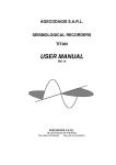
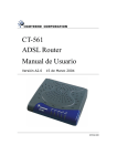
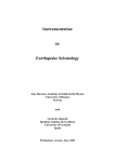
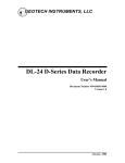
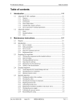
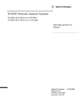
User’s manual
Agecodagis SARL
Version 15 - November 2006
$Id: userman.tex,v 1.40 2007/07/27 08:38:46 seb Exp $
1
Agecodagis SARL
http://www.agecodagis.com
Contents
1 Introduction
1.1 Signal digitisation . . . . . . . . . . . . . . . . . . . . . . . . .
1.2 Power consumption . . . . . . . . . . . . . . . . . . . . . . . .
2
2
3
2 Physical specifications
4
3 The
3.1
3.2
3.3
3.4
3.5
Osiris DAS in the field
Internal battery . . . . . .
Mass storage . . . . . . . .
Wireless lan interface . . .
DAS identification . . . .
Time control . . . . . . . .
.
.
.
.
.
.
.
.
.
.
.
.
.
.
.
.
.
.
.
.
.
.
.
.
.
.
.
.
.
.
.
.
.
.
.
.
.
.
.
.
.
.
.
.
.
.
.
.
.
.
.
.
.
.
.
.
.
.
.
.
.
.
.
.
.
.
.
.
.
.
.
.
.
.
.
.
.
.
.
.
.
.
.
.
.
.
.
.
.
.
.
.
.
.
.
.
.
.
.
.
4 Connecting to the Osiris DAS
7
8
8
9
9
9
10
5 Data management
5.1 Signal monitoring . . . . .
5.2 SeedLink connectivity . .
5.3 Retrieving data . . . . . .
5.4 Writing your own software
.
.
.
.
.
.
.
.
.
.
.
.
.
.
.
.
.
.
.
.
.
.
.
.
.
.
.
.
.
.
.
.
.
.
.
.
.
.
.
.
.
.
.
.
.
.
.
.
.
.
.
.
.
.
.
.
.
.
.
.
.
.
.
.
.
.
.
.
.
.
.
.
.
.
.
.
.
.
.
.
11
11
11
12
13
A Connector pinouts
A.1 Environemental sensors
A.2 Power . . . . . . . . .
A.3 Ethernet . . . . . . . .
A.4 Serial . . . . . . . . . .
A.5 Sensor . . . . . . . . .
A.6 GPS . . . . . . . . . .
.
.
.
.
.
.
.
.
.
.
.
.
.
.
.
.
.
.
.
.
.
.
.
.
.
.
.
.
.
.
.
.
.
.
.
.
.
.
.
.
.
.
.
.
.
.
.
.
.
.
.
.
.
.
.
.
.
.
.
.
.
.
.
.
.
.
.
.
.
.
.
.
.
.
.
.
.
.
.
.
.
.
.
.
.
.
.
.
.
.
.
.
.
.
.
.
.
.
.
.
.
.
.
.
.
.
.
.
.
.
.
.
.
.
.
.
.
.
.
.
14
14
14
14
15
15
16
.
.
.
.
.
.
.
.
.
.
.
.
B Summary of the Osiris parameters
18
C Uploading the ARM software
C.1 Using the serial line (Linux-i386 only) . . . . . . . . . . . . . .
C.2 Using osh . . . . . . . . . . . . . . . . . . . . . . . . . . . . .
C.3 Using a disk . . . . . . . . . . . . . . . . . . . . . . . . . . . .
21
21
22
22
D Filters
23
Release 15
Osiris User’s Manual
Page 2
Agecodagis SARL
http://www.agecodagis.com
Figure 1: PSD of the electronic noise measured at 2kHz.
E Logfiles
24
E.1 Osiris log file . . . . . . . . . . . . . . . . . . . . . . . . . . . 24
E.2 System messages file . . . . . . . . . . . . . . . . . . . . . . . 25
1
Introduction
Osiris stands for Open Seismological Integrated Recorder for Improved Survey. Osiris DAS is a low power digitizer and datalogger for seismological and
seismic applications. It has been designed to be used in rude environments,
for long term survey or short term deployment. The embedded system is
based on open standards and thus allows any user to develop his own applications to make Osiris a real-time remote laboratory for signal processing,
triggering, data management etc.
This documentation refers to the version 15 of the Osiris software and version
1 of the Osiris DAS.
1.1
Signal digitisation
The first stage of the digitisation is performed by a Σ/∆ 24bit ADC
(ADS1251) which samples the continuous signal at 6.144Mhz and decimates
it down to 16kHz (8kHz for the 24 channel version). The DSP then decimates
the signal down to 2kHz. The spectrum in Figure 1 represents the measured
PSD of the electronic noise for this input level, it remains at an insignificant
level compared to the full scale range (sampled at 2kHz, 24000 samples).
The user-defined sampling frequency is obtained using several decimation
filters of order 5 and 2. The user defined frequency ranges from 1Hz to 2kHz
Release 15
Osiris User’s Manual
Page 3
Agecodagis SARL
http://www.agecodagis.com
according to the following formula:
F =
2kHz
, n ≤ 4, m ≤ 3, F ≥ 1Hz
(2n .5m )
See Appendix D for the full description of these filters.
The dynamic range achieved by the Osiris DAS is 128dB at 100sps and 117dB
at 1000sps, those values correspond to a noise level of 3.2bits at 100sps and
4.8bits at 1000sps (24bits-ENOB). These values are given for an input level
without amplification. The Osiris DAS proposes up to 4 input level gains
which are factory-defined on the request of the customer. Note that the
dynamic range is slightly lower for the 24 channel Osiris version.
1.2
Power consumption
The internal design of the DAS, based on a DSP microcontroller coupled
with a ARM processor allows for an intelligent power management. This
task is assumed by the software which takes care of turning off any unused
device (mass storage, GPS, communication device, etc.). Table 1 gives the
measured power consumption far various usages at 100 and 1000sps for 6
channels.
Thanks to the use of an internal data buffer of 10Mb, the disk activity is
reduced to less than 5 seconds per hour at 100sps (average for 6 channels).
The data are flushed to the mass storage medium only when the internal data
buffer filling rates reaches 80% and the mass storage medium is turned off
as soon as this operation is completed. The acquisition software is designed
to bypass the internal buffer and directly write the data on the mass storage
medium if the data flow requires a permanent flush (high sample frequency
componenent
6ch@250sps
GPS
Wireless lan
CompactFlash (writing)
MicroDrive (writing)
PCMCIA HD
low power mode
power
1,2W
0,9W
1,6W
120mW
480mW
1,44W
780mW
Table 1: Typical measured power consumptions of the Osiris DAS
Release 15
Osiris User’s Manual
Page 4
Agecodagis SARL
http://www.agecodagis.com
and/or high channel number). The optional communication devices (PCMCIA devices) are also controlled by the embedded software and can be turned
on/off on user request.
2
Physical specifications
The Osiris DAS is packed in a single case containing both the digitiser and
the datalogger in order to make the transport, storage and manipulation
easy. The case is a Pelican 1300 Pelicase (R), it is a light-weight and robust
case, compliant with the IP67 standard.
Volume : 270x250x170
Weight : 3.5kg
IP67
Figure 2 shows some views of the Osiris DAS. The dimensions are small and
the cases offer the possibility to be piled up, remaining locked thanks to
the reliefs on the top and bottom. The connectors are located on the back
face of the case, protected by the lateral relief of the case (see Figure 3).
The connector set follows the standard HE301, MIL-C 26482G (IP68) (see
Appendix A for the pinouts):
power supply : 85107 A 8 - 3 pins
sensor : 85107A 14 - 12 pins, 1 connector per 3 channels
ethernet : 85107 A 12 - 8 pins
RS232 : 8510 A 12 - 10 pins
antenna radio : N
GPS : 85107 A 10 - 6 pins
environment monitoring : 85107 A 12610W 10 pins
The top face shows a panel with a figure representing the connector location
with their usage (Figure 3, bottom left) and a status panel (Figure 4). The led
panel is turned off in normal operation (to reduce the power consumption),
Release 15
Osiris User’s Manual
Page 5
Agecodagis SARL
http://www.agecodagis.com
Figure 2: Top and bottom left: Front and top views of the Osiris DAS
showing the handle on the front face. Bottom right: back view of the case
showing the connectors protected by the relief of the case.
Release 15
Osiris User’s Manual
Page 6
Agecodagis SARL
http://www.agecodagis.com
Figure 3: Back face presenting the connectors with the map indicating the
connector usage.
Figure 4: Top face showing the connector usage and the LED-based status
publication panel.
Release 15
Osiris User’s Manual
Page 7
Agecodagis SARL
http://www.agecodagis.com
Figure 5: The internal panel: the WiFi/mass storage slots LED activity and
the maintenance keys.
when the user wants to know the state of the DAS, he just gives a small
knock on the panel to turn on the led panel, switch the GPS on and wake
up the radio card (if any).
The choice of a led-based panel in stead of an LCD panel allows a clear understanding of the information even in difficult operating conditions (darkness,
humidity, direct sun exposure...).
When the case is open, a panel protecting the internal part of the station
from the projections of water, mud, or small objects appears (Figure 5).
The panel also supports the slots used for the mass storage media or a
PCMCIA communication device (modem, radio modem, WiFi...). Two leds
inform the user that the corresponding mass storage medium is presently
used. When the led is off, the user can remove the medium. Unplugging
the medium when the led is on cause damages to the medium and can result
in an unreadable disk. Three maintenance buttons are also available on the
internal panel. They should not be used during the normal operation of the
DAS. ’DSP upload’ and ’ARM upload’ are used to upgrade the firmware of
the DSP or the ARM (respectively). ’Default param’ resets the configuration
to the factory defined set of parameters and also reformat the flash storage
area (when pressed during powerup). Finally two switches are used to select
the operating mode of the GPS (presently, only the ’Hard’ mode should be
used) and to completely disconnect the internal LiOn battery (for long term
storage).
Release 15
Osiris User’s Manual
Page 8
Agecodagis SARL
http://www.agecodagis.com
ARM
osh www/server
configuration
sysd
trigger
Sensors
SEISMO
DSP
ADC0,1,2,3...
Data
Cmd
DSP clock
PPS
User input
LEDS/TILT
Mass storage (HD)
PCMCIA
Mass storage (HD)
PCMCIA
diskmgr
TCXO
Filtering,
decimation
trigger
acquisit
ENV.CH
RJ45
WiFi
Eth
comd
RS232
PPP
Serial console login
RTC
Sys. clock
GPSD time manager
RS232
GPS
Internal
battery
External
power supply
Figure 6: Overview of the Osiris DAS internals and software.
3
The Osiris DAS in the field
Figure 6 shows the two-processor architecture of the Osiris DAS and illustrates the relations of the different components.
3.1
Internal battery
The Osiris DAS is equipped with a 2900mAh internal battery. The internal
battery is charged using the main power supply. It is used provide energy
in case of main power failure, to complete a proper shutdown in case of long
power failure and to maintain the DSP internal clock.
3.2
Mass storage
The data are first stored on the flash memory area and then transferred to
the PCMCIA storage devices.
3.2.1
Flash storage area
The flash storage area is a persistent memory area where the data are stored
before being transferred to the storage area. This intermediate step is needed
Release 15
Osiris User’s Manual
Page 9
Agecodagis SARL
http://www.agecodagis.com
to reduce the power consumption. If the data transfer rate is too high, the
embedded software bypasses the flash memory area and directly saves the
data on the PCMCIA storage area. This will occur if the total number of
samples per second is higher than 6*1000.
3.2.2
PCMCIA storage area
The data files are finally stored on the PCMCIA mass storage plugged in one
of the two slots available in the Osiris DAS. Remember that removing the
PCMCIA device from the slot while the activity led is ON may cause serious
damages to the device and leave the DAS in an unstable state.
3.3
Wireless lan interface
The Osiris DAS has been succesfully tested with PCMCIA wireless cards
based on the Prism2.5 chipset. Support for these cards is included in the
standard Osiris system.
3.4
DAS identification
Each Osiris DAS has a unique serial number written on the case. This serial
number is used as HOSTID. The HOSTID is the system level DAS identification
it is computed by the system and is always unique. The MAC address of the
eth0 interface defines the IP addresses of the DAS.
The IP addresses of the network interfaces of any Osiris DAS are automatically defined at boot time. During normal operations, the IP address used
for each station is directly deriverd from the serial number: the Osiris DAS
AABBCC has the IP address 10.AA.BB.CC
The full serial number/IP address table is published online on http://www.agecodagis.com
(Support... Documentation... Osiris).
3.5
Time control
The timing accuracy for the Osiris DAS is better than 1µs, which is typically
the GPS time accuracy. The internal clock is based on a TCXO quartz
(temperature constrained clock), the stability of the TCXO is +/- 1ppm.
The drift for the internal clock is 10−6 . Since the ADC (one per channel)
operate synchronously, the channel to channel skew is zero.
Release 15
Osiris User’s Manual
Page 10
Agecodagis SARL
http://www.agecodagis.com
The propagation time through the decimation filters is given by the following
formula:
127
126
δT =
+ (4 ∗ 5m ∗ 2n − 3 ∗ 5m − 1) ∗
32000
16000
n and m refer to the numbers of decimations of order 2 and 5, respectively.
The latest version of cvtit takes into account these delays.
The GPS receiver provides a continuous time signal over a NMEA connection (open standard GPS protocol communication). A specialised daemon
running on the ARM processor uses this time information to synchronise the
system clock as well as the real time clock of the ARM processor. Once
per minute, the GPS daemon lets the time signal propagate to the DSP.
This time pulse is used by the DSP to time stamp the data flow which are
sent back to the acquisition software. This process allows for a very robust
time management for the DSP as well as for the ARM part of the system.
The acquisition software and the GPS daemon both log the time information
allowing for a full a posteriori control of the time-stamp process.
3.5.1
Hardware real time clock, no-GPS mode
The Osiris DAS is equipped with a hardware real time clock (RTC). The RTC
is set to the GPS time when a valid time information is received. When
the system starts, the RTC time is used as a fisrt estimation of the time
(the accuracy of the RTC is 1s). The embedded DSP on the other hand is
equipped with a very accurate (10−6 s) TCXO-based clock. The use of both
clocks allows for the computation of the absolute time that will be used in
the data stream.
If the main power is suspended with the power supply connector still plugged
in the Osiris DAS, then the DSP will maintain its internal TCXO clock using
the internal battery. The time drift thus remains continuous and the DAS
can be used later without GPS since the DSP remains informed of the time.
Note that in order to benefit this feature, the switch controlling the internal
battery must be in the ’ON’ position.
4
Connecting to the Osiris DAS
Osiris accepts connections on all its active network interfaces on the ports 23
(telnet), 80 (osh WWW interface), and 2323 (osh interface). An ssh server
is also available and ready to be installed on Osiris if required.
Release 15
Osiris User’s Manual
Page 11
Agecodagis SARL
http://www.agecodagis.com
The osh server listens the port 2323, a single session implements the full
osh protocol for remote connections, allowing the configuration and data
management.
A SeedLink server is embedded in Osiris, the server is listening port 18000
and serves only the real-time data requests. Please refer to section for details.
5
Data management
Data are stored in files encoded in TITAN2 format. The release 7.9 (or later)
of cvtit is able to correctly read this format and to convert the data in
various commonly used seismological data formats.
5.1
Signal monitoring
A java applet is embedded in Osiris, it can be used to monitor the data
streams in real time. The monitor flow is limited to a maximum of 2000
samples/s over the total number of channels, e.g. at 500Hz, no more than 4
channels are available.
The same applet can be used to monitor several DAS (multi station monitoring), this feature absolutely requires the use of a 1.4 JRE, any previous
version won’t allow the multi station monitoring. The multi station monitoring is simply activated by starting the monitor applet from the first DAS and
then connecting to the other DAS and asking for the data without restarting
the applet. Note that as the DAS will contact the applet, the applet IP
address should be reachable on port 2004 from the DAS.
Please check that your system is correctely configured to run java plugins using the following tool: http://www.java.com/en/download/help/testvm.jsp.
5.2
SeedLink connectivity
The SeedLink server embedded in Osiris provides a simple way to connect an
Osiris DAS to an Earthworw system, or any similar data management system
implementing a SeedLink client. The SeedLink server listens on port 18000.
The default names for the channels are ’C00’ to ’C23’ and the network and
location are set to ’AG’ and ’00’ (resp.). The parameters ’NetworkName’
and ’LocationName’ control these names.
Release 15
Osiris User’s Manual
Page 12
Agecodagis SARL
http://www.agecodagis.com
Note that the station name stored in the MiniSeed blockettes will be trucated
to the first 5 characters of the parameter ’StationName’.
The following command line starts SeisGram (http://alomax.free.fr/seisgram/seedlink/)
in Seedlink mode and monitors the stream AG TEST:C?? from the Osiris
DAS with address 10.64.0.10:
java -jar SeisGram2K40.jar \
-seedlink "10.33.0.10:18000#AG_TEST:C??#120"
Please refer to the following links for more information about Seedlink:
• SeisComP:
http://www.gfz-potsdam.de/geofon/seiscomp/welcome.html
• MERIDIAN:
http://orfeus.knmi.nl/meredian/
• Java SeedLink implementation:
http://alomax.free.fr/projects/seedlink/index.html
5.3
Retrieving data
The recommended way to get the data stored on an Osiris DAS is using the
html interface or the data extract commands of osh.
5.3.1
Data transfer with the osh command line interface
The following command, issued in a oclient session asks for the data stored
on the storage disk corresponding to the time range 2004/07/01-16:00:00 to
2004/07/01-17:00:00, on channels 0 to 2
connect [station]
data extract=storage,2004/07/01-16,2004/07/01-17,0-2 > data.tit
Note that since version 006, the ’auto’ pseudo-device can be used in stead of
’storage’ or ’flash’. In this case, the system will first look for the beginning
of the data in flash. On a succesful search, the extract command will run
only from flash. The storage disk is used as a fall back if the beginning of
the request is not found in flash. Note that in some particular cases, the
beginning of the data may be found in flash while the end resides on the
storage disk. No mechanism is designed to take into account these particular
cases.
Release 15
Osiris User’s Manual
Page 13
Agecodagis SARL
5.3.2
http://www.agecodagis.com
Data transfer with the osh WWW interface
The ’data management’ link in the main page of osh allows to list the files
stored on the DAS. Then, the links on the files can be used to store the file
on the computer or to directly see the seismograms in SeisGram2K.
Under windows, after the installation of the viewer, the ’TIT’ files should
be viewed autmatically with SeisGram2K. Under Linux, when opening a
TITAN file for the first time, Mozilla should ask which application to use, just
select /usr/local/bin/viewtitan. Mozilla should remember this setting for the
further operations. This has been tested in the Gnome environment, running
Mozilla 1.7 (FC2 distribution) with the JRE 1.4 from http://java.sun.com
5.4
Writing your own software
The real time data are published for the channels sampled at less than 500Hz
only. The Osiris library provides the function to be used for accessing these
data. Osiris/Software/SoftArm/OsirisSrc/Src/Tools/UserProc on the
CVS server gives an example of the real time data reading and processing.
Release 15
Osiris User’s Manual
Page 14
Agecodagis SARL
A
A.1
http://www.agecodagis.com
Connector pinouts
Environemental sensors
Reference: 851-06EC-12-10PW50 (10 pins)
Connector Pin Osiris In/Out
A
Out
B
In
C
D
Out
E
In
F
In
G
In
H
In
J
In
K
In
A.2
Label
Power supply fuse
DTR DSP board
GND
RXD DSP board
Env. chan. 7
Env. chan. 6
Env. chan. 4
Env. chan. 3
TXD DSP board
Env. chan. 5
Power
Reference: 851-06EC-8-3P50 (3 pins)
Connector Pin
A
B
C
A.3
Osiris In/Out
In
In
Label
Save time (to GND)
Power supply
GND
Ethernet
Reference: 851-06EC-12-8P50 (8 pins)
Connector Pin
A
B
C
D
E
F
G
H
Release 15
Osiris In/Out
Out
Out
In
In
Out
Out
Label
TxD+
TxDGND
RxD+
RxDGND
Fuse
Fuse
Osiris User’s Manual
Page 15
Agecodagis SARL
A.4
http://www.agecodagis.com
Serial
Reference: 851-06EC-12-10P50 (10 pins)
Connector Pin Osiris In/Out
A
In
B
In
C
Out
D
Out
E
F
In
G
Out
H
Out
J
In
K
In
A.5
Label
RI
CTS
RTS
Fuse
GND
DCD
TxD
DTR
DSR
RxD
Sensor
Reference: 851-06EC-14-12P50 (12 pins), for 3, 6 or 9 channels:
Connector Pin
A
B
C
D
E
F
G
H
J
K
L
M
Osiris In/Out
In
In
In
In
In
In
Out
Out
Out
Label
S0+
S0S1+
S1S2+
S2Calibration
Mass centering (5V)
GND ANALOG
SHIELD
Power supply
GND
Reference: 851-06EC-18-32P50 (32 pins), for 12 and 24 channels:
Release 15
Osiris User’s Manual
Page 16
Agecodagis SARL
http://www.agecodagis.com
Connector Pin Osiris In/Out
A
In
B
In
C
In
D
In
E
In
F
In
G
In
H
In
J
In
K
In
L
In
M
In
N
In
P
In
R
In
S
In
T
In
U
In
V
In
W
In
X
In
Y
In
Z
In
a
In
b
Out
c
Out
d
e
f
g
h
j
A.6
Label
V2- Triplet3
V2+ Triplet3
V1- Triplet3
V1+ Triplet3
V0- Triplet3
V0+ Triplet3
V2- Triplet2
V2+ Triplet2
V1- Triplet2
V1+ Triplet2
V0- Triplet2
V0+ Triplet2
V2- Triplet1
V2+ Triplet1
V1- Triplet1
V1+ Triplet1
V0- Triplet1
V0+ Triplet1
V2- Triplet0
V2+ Triplet0
V1- Triplet0
V1+ Triplet0
V0- Triplet0
V0+ Triplet0
Recalage Masses 5V
Calibration
GND ANALOG
SHIELD
GND
Power supply
Power supply
GND
GPS
Reference: 851-06EC-10-6P50 (6 pins)
Release 15
Osiris User’s Manual
Page 17
Agecodagis SARL
Connector Pin
A
B
C
D
E
F
Release 15
http://www.agecodagis.com
Osiris In/Out
Out
In
In
Out
Out
Label
TxD
GND
RxD
1pps
Remote
Fused PowerSupply (2A)
Osiris User’s Manual
Page 18
Agecodagis SARL
B
http://www.agecodagis.com
Summary of the Osiris parameters
The following table describes the parameters as seen from the osh command
line. The osh web interface provides an easier access to the configuration.
Release 15
Osiris User’s Manual
Page 19
Agecodagis SARL
Name
http://www.agecodagis.com
Type
Range
Default
Duration (s) of the LEDS activity after a knock on the DAS and at boot time:
LedsOnDuration
N
10-*
300
Assignation of physical channels to logical channels. A value of 24 turns the logical channel off. This allows to register the same physical channel with different
sampling rates:
LogicalChannel0–23
N
0-23,24
1:1
10-1000
500
Sampling rate for the logical channels
FsChannel0–23
N
Short term average window length used for trigger (s):
KStaChannel0–23
N
0.01-3600
0.3
Long term average window length used for trigger (s):
KLtaChannel0–23
N
0.01-3600
10
1–128
4
Threshold ratio STA/LTA used for trigger:
ThresholdChannel0–23
N
Gain index for each channel. The gains are factory defined on user request:
Gain0–23
N
0-3
0
A
*
hostid
*
AG
*
CH0–23
*
00
120–3600
120 (fixed)
Station name:
StationName
Network name (for SeedLink):
NetworkName
A
Channel names (for SeedLink):
SeedChannel0–23
A
Location names (for SeedLink):
LocationName0–23
A
Maximum length (s) of the data files (unused):
FileDuration
N
Recording mode: based on STA/LTA, preconfigured time window or external pulse:
RecordingMode
A
stalta/window/extern/continuous
continuous
What to do when the storage disk is full (cycle/stop/backup:
StoragePolicy
A
*
cycle
Duration (s) of signal registerd before a triggered event:
PreEvent
N
0-30
10
Duration (s) of signal registerd after a triggered event:
PostEvent
N
0-*
120
Bit mask defining which channles are used to trigger events:
TriggerChannelMask
N
0x0fff
0
true/false
false
true/false
false
Activate the slave trigger mode ?
slaveTrigger
A
Activate the master trigger mode ?
masterTrigger
Release 15
A
Osiris User’s Manual
Page 20
Agecodagis SARL
Name
http://www.agecodagis.com
Type
Range
Default
Right shift of the data before beeing sent to the monitor (division by 2**MonitorShift):
MonitorShift
N
0-23
0
Bit mask defining which channels are to be sent to the monitor:
MonitorChannels
N
0x0fff
0
Monitored data type (0=MinMax, 1=LTA, 2=data):
MonitorType
N
0-2
0
How long should the radio be powered (s):
RadioMaxDuration
N
0(forever)-86400
0(forever)
How often should the radio be powered on a day:
RadioCycle
N
0(no cycle)-96
24(each hour)
How long should the GPS be powered (s):
GPSMaxDuration
N
0(forever)-86400
600
How long should the GPS sleep (s):
GPSSleepTime
N
0(forever)-86400
3600
How many pulses should be received by the GPS:
GPSMinPulses
N
0(infinity)-*
5
Should the GPS be powered when a tily occurs ?
GPSOnTilt
A
on/off
on
Should the WWW interface start in triplet mode ?
TripletMode
Release 15
N
0(no)/1(yes)
Osiris User’s Manual
3600
Page 21
Agecodagis SARL
C
http://www.agecodagis.com
Uploading the ARM software
The binary package of the Osiris software are distributed as compressed tar
archives containing all the necessary tools.
tar xvzf Package-name.tgz
cd Package-directory
During the first boot following an upgrade of the Osiris system, the flash
storage area is formatted to ensure that the system starts in a clean state.
All the configuration parameters are reset to their default value, the task list
is lost, as well as any modified network parameters.
Note that this first boot takes about 3 minutes.
After this boot, the DAS is reachable using the IP addresses written on the
top of the case.
C.1
Using the serial line (Linux-i386 only)
The update of the Osiris software is quite simple: just plug the serial cable
between your computer and the Osiris DAS (connector ’ppp’), start the script
flash givin the appropriate serial port as unique argument, and carefully
follow the instructions. The upload can be performed using both ethernet
and serial cable (fast) or only the serial cable (slow).
Example:
./flash /dev/ttyS0
or
./flash /dev/ttyS0 serial
for the serial-only upload.
When the script asks for the DAS to be turned on, press on the ’ARM Upload’ key on the DAS and plug the main battery cable. The ’ARM Upload’
can be released as soon as the process has been initiated. After the end of
the upload process, the station must be physically turned off and the user
should wait a few seconds before turning on the station.
Be sure no other process is using the serial line on the computer.
If the first step of the upload process fails, unplug the serial cable, switch the
DAS off and restart.
Release 15
Osiris User’s Manual
Page 22
Agecodagis SARL
C.2
http://www.agecodagis.com
Using osh
The ARM upload procedure can also be done on a living DAS running osh.
./oUpload osiris_IP_address
This command connects to the specified Osiris host, and transfers the images. When the transfer is finished, the DAS is rebooted within 30 seconds.
The command must be started in the directory where reside rootfs.img and
kernel.img. If for any reason this process fails, use the serial line method to
upgrade the Osiris DAS.
Upgrading from version 15 or later will preserve the network configuration,
parameters and task list.
C.3
Using a disk
Connect an Osiris disk containing the files rootfs.img and kernel.img in the
the top directory and wait for the reboot.
Upgrading from version 15 or later will preserve the network configuration,
parameters and task list.
Release 15
Osiris User’s Manual
Page 23
Agecodagis SARL
D
http://www.agecodagis.com
Filters
The first filter applies for downsampling the data from 16kHz to 2kHz. It
is defined by 128 coefficients given in file dec8.dat. Then, the user sampling
frequency is reached by applying decimators by 5 and 2 (in this order) defined
by the coefficents given in files dec5.dat and dec2.dat (resp.).
Release 15
Osiris User’s Manual
Page 24
Agecodagis SARL
E
http://www.agecodagis.com
Logfiles
The Osiris system maintains three log files that are all managed in the same
way: the more recent part of the log resides on the flash/ram filesystem, and
the older part is stored on the storage device. The length of the log file on
the storage device cannot be more than 10Mb. When this limit is reached,
the file are truncated and only the more recent 5Mb are kept.
E.1
Osiris log file
The types of event logged in this file are STATUS, DISK, and GPS. Periodically, a title line is issued, explaining the format of each type of event.
Note that the informations published in the osiris.log since instantaneous
since they are obtained from the various subsystems of Osiris when the line
is added to the file.
2005/11/11-12:11:56 #STATUS: CPU EXTBATT INTBATT TEMP ENV0 ENV1 \
ENV2 ENV3 ENV4
2005/11/11-13:26:23 #DISK: ST.SN ST.TOTAL ST.FREE FL.TOTAL FL.FREE \
THROUGHPUT ST.MOUNTED FLUSH RADIO
2005/11/09-17:00:00 #GPS: POWER INUSE/INVIEW LAT LON ALT PDOP HDOP \
VDOP TDOP QUAL/VALID STATE
• STATUS line (frequency: about once per minute)
– CPU: cpu load
– EXTBATT: external battery voltage
– INTBATT: internal battery voltage
– TEMP: station temperature (when applicable)
– ENV0-ENV4: environnemental channel 0-4 (when applicable)
• DISK line (frequency: about once per 5 minutes)
– ST.SN: storage device serial number
– ST.TOTAL: storage device total size (1Kbyte blocks)
– ST.FREE: storage device free space (1Kbyte blocks)
– FL.TOTAL: flash device total size (1Kbyte blocks)
– FL.FREE: flash device free space (1Kbyte blocks)
Release 15
Osiris User’s Manual
Page 25
Agecodagis SARL
http://www.agecodagis.com
– THROUGHPUT: data throughput
– ST.MOUNTED: storage device mount state
– FLUSH: is a flush running ?
– RADIO: is a wireless card present ?
• GPS line (frequency: about once per 5 minutes)
– POWER: GPS power state
– INUSE/INVIEW: number of stellites used and viewed
– LAT, LON, ALT: location reported by the GPS receiver
– PDOP, HDOP, VDOP, TDOP: dilution of precision for position,
horizontal position, vertical position, time (resp.)
– QUAL/VALID: flag (0:1) indicating that position quality is considered good and time valid
– STATE: GPS receiver state
Please note that the GPS line reports the instantaneous position, in order
to get the averaged position, use the ’gps’ command in osh and refer to the
AvgLat, AvgLon, and AvgAlt fields.
E.2
System messages file
The system messages file collects all the syslog-generated messaged as well
as some messages generated by the kernel. Some of the Osiris processes use
syslog to generate error or debug messages. This file should not be used for
normal operations.
Release 15
Osiris User’s Manual
Page 26
Agecodagis SARL
http://www.agecodagis.com
Change history
20060919seb
20060912seb
20060808seb
20060303seb
20060207seb
20060104seb
20051227seb
20051219seb
20051010seb
20050929seb
20050408seb
20050407seb
20050407seb
20050407seb
20050509seb
Release 15
updated the power consumption for the new input stage
version 010 tcxo adjustment and FTP client added
pinout of the GPS was wrong (Rx/Tx)
version 007.
mention minicom/hyperterminal for console login
corrected the connector reference
"data extract=auto"
final version 005
updates for version 005, added logfiles
updated for version 004
mention the 36-36000Hz limitation
start of history
added the 12channel connector pinout
quickconf: specification of the external trigger
signal
quickconf: note about FW and ’-set’ option in nrtd
Osiris User’s Manual
Page 27