1
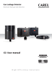
Gas Leakage Detector Electronic fixed gas leak detectors with LED indicators for Power and Alarm User manual NO POWER & SIGNAL CABLES TOGETHER READ CAREFULLY IN THE TEXT! H i g h E f f i c i e n c y S o l u t i o n s ENG IMPORTANT IMPORTANT NO POWER & SIGNAL CABLES TOGETHER READ CAREFULLY IN THE TEXT! CAREL bases the development of its products on decades of experience in HVAC, on the continuous investments in technological innovations to products, procedures and strict quality processes with in-circuit and functional testing on 100% of its products, and on the most innovative production technology available on the market. CAREL and its subYESdiaries nonetheless cannot guarantee that all the aspects of the product and the software included with the product respond to the requirements of the final application, despite the product being developed according to start-of-the-art techniques. The customer (manufacturer, developer or installer of the final equipment) accepts all liability and risk relating to the configuration of the product in order to reach the expected results in relation to the specific final installation and/ or equipment. CAREL may, based on specific agreements, act as a consultant for the poYEStive commisYESoning of the final unit/application, however in no case does it accept liability for the correct operation of the final equipment/ system. WARNING: separate as much as possible the probe and digital input signal cables from the cables carrying inductive loads and power cables to avoid possible electromagnetic disturbance. Never run power cables (including the electrical panel wiring) and signal cables in the same conduits. The product must be installed with the earthconnected, using the special yellow-green terminal on the terminal block. Do not use the neutral for the earth connection. The CAREL product is a state-of-the-art product, whose operation is specified in the technical documentation supplied with the product or can be downloaded, even prior to purchase, from the webYESte www.CAREL.com. Each CAREL product, in relation to its advanced level of technology, requires setup / configuration / programming / commisYESoning to be able to operate in the best possible way for the specific application. The failure to complete such operations, which are required/indicated in the user manual, may cause the final product to malfunction; CAREL accepts no liability in such cases. DISPOSAL Only qualified personnel may install or carry out technical service on the product. The customer must only use the product in the manner described in the documentation relating to the product. INFORMATION FOR USERS ON THE CORRECT HANDLING OF WASTE ELECTRICAL AND ELECTRONIC EQUIPMENT (WEEE) In addition to observing any further warnings described in this manual, the following warnings must be heeded for all CAREL products: • Prevent the electronic circuits from getting wet. Rain, humidity and all types of liquids or condensate contain corroYESve minerals that may damage the electronic circuits. In any case, the product should be used or stored in environments that comply with the temperature and humidity limits specified in the manual. • Do not install the device in particularly hot environments. Too high temperatures may reduce the life of electronic devices, damage them and deform or melt the plastic parts. In any case, the product should be used or stored in environments that comply with the temperature and humidity limits specified in the manual. • Do not attempt to open the device in any way other than described in the manual. • Do not drop, hit or shake the device, as the internal circuits and mechanisms may be irreparably damaged. • Do not use corroYESve chemicals, solvents or aggressive detergents to clean the device. • Do not use the product for applications other than those specified in the technical manual. In reference to European Community directive 2002/96/EC issued on 27 January 2003 and the related national legislation, please note that: 1. WEEE cannot be disposed of as municipal waste and such waste must be collected and disposed of separately; 2. the public or private waste collection systems defined by local legislation must be used. In addition, the equipment can be returned to the distributor at the end of its working life when buying new equipment. 3. the equipment may contain hazardous substances: the improper use or incorrect disposal of such may have negative effects on human health and on the environment; 4. the symbol (crossed-out wheeled bin) shown on the product or on the packaging and on the instruction sheet indicates that the equipment has been introduced onto the market after 13 August 2005 and that it must be disposed of separately; 5. in the event of illegal disposal of electrical and electronic waste, the penalties are specified by local waste disposal legislation. Warranty on the materials: 2 years (from the date of production, excluding consumables). Approval: the quality and safety of CAREL INDUSTRIES Hqs products are guaranteed by the ISO 9001 certified design and production system. All of the above suggestions likewise apply to the controllers, serial boards, programming keys or any other accessory in the CAREL product portfolio. CAREL adopts a policy of continual development. Consequently, CAREL reserves the right to make changes and improvements to any product described in this document without prior warning. The technical specifications shown in the manual may be changed without prior warning. The liability of CAREL in relation to its products is specified in the CAREL general contract conditions, available on the webYESte www.CAREL.com and/or by specific agreements with customers; specifically, to the extent where allowed by applicable legislation, in no case will CAREL, its employees or subYESdiaries be liable for any lost earnings or sales, losses of data and information, costs of replacement goods or services, damage to things or people, downtime or any direct, indirect, incidental, actual, punitive, exemplary, special or consequential damage of any kind whatsoever, whether contractual, extra-contractual or due to negligence, or any other liabilities deriving from the installation, use or imposYESbility to use the product, even if CAREL or its subYESdiaries are warned of the posYESbility of such damage. 3 “Gas Leakage Detector” +0300035EN - rel. 1.3 - 06.12.2013 ENG Content 1. INTRODUCTION 1.1 1.2 1.3 1.4 1.5 1.6 Description ......................................................................................................................7 Codes ..................................................................................................................................7 Calibration requirements .......................................................................................7 Maintenance ..................................................................................................................7 Technical specifications...........................................................................................7 Dimensions and mounting ...................................................................................8 2. INTRODUCTION 2.1 2.2 2.3 2.4 2.5 2.6 2.7 2.8 2.9 2.10 2.11 2.12 18 Element sensors ........................................................................................................18 Calibration Cup Datasheet .................................................................................18 5. MODBUS RTU PROTOCOL 5.1 5.2 5.3 5.4 16 General warnings .....................................................................................................16 Bump Test .....................................................................................................................16 Calibration ....................................................................................................................16 Additional recommendations ........................................................................17 4. ACCESSORIES 4.1 4.2 9 Display functions .........................................................................................................9 Modbus connections................................................................................................9 Setting the communications Baud Rate.......................................................9 Location of Sensors ...................................................................................................9 Machinery rooms .......................................................................................................9 Refrigerated Spaces ...................................................................................................9 Chillers................................................................................................................................9 Air Conditioning – Direct systems VRF/VRV.............................................10 Test/Function instructions ..................................................................................10 Trouble Shooting......................................................................................................10 Electrical connection diagram examples ..................................................11 Electrical connections and configuration .................................................12 3. CHECK AND CALIBRATION PROCEDURE 3.1 3.2 3.3 3.4 7 20 Modbus RTU (Remote Terminal Unit) Protocol......................................20 Address ...........................................................................................................................20 Register Map ...............................................................................................................20 Variable list:...................................................................................................................25 5 “Gas Leakage Detector” +0300035EN - rel. 1.3 - 06.12.2013 ENG 1. INTRODUCTION 1.1 Description 1.3 Calibration requirements DPWL* represent a range of electronic fixed gas leak detectors with LED indicators for Power and Alarm. They have direct output relays, as well as voltage and current outputs and Modbus communication. Local standards may require control procedures for sensor calibration. The main relevant standards require testing and calibration at least once a year. The semiconductor sensors are calibrated for a specific gas. The first calibration is performed by the manufacturer, subsequent calibrations are performed by the installer. They are designed for detection of refrigerant leaks to the atmosphere in Coldrooms, Freezer rooms, Plantrooms, plant enclosures, and other areas where refrigeration plant is likely to be located. The refrigerant gas leak sensor is a device that signals leakages of common gases (R22, R134a, R404a, R407a, R407c, R410a, NH3, Ethylene and CO2). It can be used in stand-alone applications, or integrated into Carel controllers or third party devices. Connection to Carel controllers is made using an analogue or digital output or Modbus® RS485 serial connection. When leaks are detected exceeding a certain concentration, the sensor sends an alarm signal to the controller, activating a local audible and visual warning and a relay (SPDT). 1.4 Maintenance Annual testing Every 3 years Every 5/6 years Tests must be performed annually to meet EN378 and F-GAS standards Calibration recommended Gas sensor replacement and calibration recommended Tab. 1.b Check local regulations on calibration or testing requirements. This allows prompt identification of gas leaks, avoiding having to shut the unit down and at the same time guaranteeing the safety of any people in the vicinity. After exposure to a substantial gas leak, element sensor should be checked and replaced if necessary. Each model is calibrated for a specific gas and is typically installed in new or existing buildings that require continuous monitoring of gas leaks. Installation of the device ensures compliance with European standards F-GAS and EN378 as well as ASHRAE 15. Note: following a significant gas leak with extended exposure, check and if necessary replace the sensor. Available in semiconductor or infrared version with enclosure IP41 and IP66 built-in and with remote sensor. 1.5 Technical specifications Semiconductor version R22, R134a, R404a, R407c, R410a, NH3, Ethylene 1.2 Codes The Gas Detector is available in two sensor versions: Semiconductor (SC) for refrigerants and infrared (IR) for CO2 e con sensore remoto e cavo 5m. Semiconductor (IP41) DPWLA07000 DPWLB07000 DPWLC07000 DPWLR07000 DPWLD07000 DPWLE07000 DPWLG07000 DPWLQ07000 Infrared (IP41) Semiconductor with 5 m remote sensor (IP66) DPWLA27000 DPWLB27000 DPWLC27000 DPWLD27000 DPWLE27000 DPWL417000 Options: 6133015AXX Descrizione R22 gas leak detector R134a gas leak detector R404a gas leak detector R407a gas leak detector R407c gas leak detector R410a gas leak detector NH3 gas leak detector ETHYLENE gas leak detector Infrared (IP66) Infrared with 5 m remote sensor (IP66) DPWLK07000 DPWLL07000 DPWLM07000 DPWLN07000 DPWL427000 Typical operating range: Operating conditions: Non-condensing humidity: Estimated sensor life: Alarm threshold Reset time Linearity Operating range: Descrizione R134a gas leak detector R404a gas leak detector R407a gas leak detector R410a gas leak detector CO2 gas leak detector 6133019AXX “HCFC, HFC and ETHYLENE refrigerant gas sensor for semiconductor version HCFC, HFC and ETHYLENE refrigerant gas sensor for semiconductor version cable 5m “NH3 refrigerant gas sensor - for semiconductor version” 6133016AXX 6133018AXX CO2 refrigerant gas sensor - for infrared version CO2 refrigerant gas sensor - for infrared version cable 5m DPWLKIT000 DPWLKIT010 DPWLKIT100 Calibration adapter (hose and hood) Calibration adapter (hose and 4 hoods) Protection against water spray for IP66 version 6133017AXX Power supply: Power consumption (at 12V): Monitoring active: Alarm display: Audible alarm: Fault during monitoring: Fault status: Analogue output: Serial communication: Digital output: Selectable delay: IP protection: Infrared version CO2 Infrared version R134A, R404a, R407a, R410a 12/24V+20% dc/ac 50/60 Hz 153mA, 136mA Green LED Red LED enabled/disabled Red LED ON - Green OFF 1V, 2mA 1V, 2mA 0-5V, 1-5V, 0-10V, 2-10V, 4-20mA Modbus® RS485 1 relay rated at 1 A/24 Vdc/ac 0, 1, 5, 10min IP41 built-in version IP66 IP66 built-in and remote remote sensor version sensor 0-1,000 ppm 0-10.000 ppm -20T50ºC -40T50°C -20T50°C 0 to 95% 5-8 years 100 ppm 1500 ppm 100 ppm 600 s 210 s on calibration field • HCFC = 10 to 1,000 ppm (semiconductor vers.) • HFCs =10 to 1,000 ppm (semiconductor vers.) • Carbon Dioxide = 0 to 10,000 ppm (infrared vers.) Tab. 1.c Tab. 1.a 7 “Gas Leakage Detector” +0300035EN - rel. 1.3 - 06.12.2013 ENG 1.6 Dimensions and mounting Version IP44 Version IP66 Mounting Mounting and Dimensions 5 mm Max 122 mm 53 04.5 43.0 123 mm 120 120 103.50 09.0 144 mm 7.0 86.0 85 mm mounting measurements m 101 mm 0 4 .5 0 25.00 mounting slots = 9mm long x 6mm wide use 5mm - 6mm screws m 75 m 8.0 50 m 42 mm 59 mm 36.00 146 mm 25.00 Fig. 1.c Fig. 1.a Version IP66 with remote sensor Dimensions 53 mm 144 mm 42 mm 5 mm 101 mm 10 mm mounting measurements 123 mm 120 mm 122 mm mounting slots = 9mm long x 6mm wide use 5mm - 6mm screws 59 mm m 50 m 86 mm 146 mm m 75 m Fig. 1.b Fig. 1.d “Gas Leakage Detector” +0300035EN - rel. 1.3 - 06.12.2013 8 85 mm ENG 2. INTRODUCTION 2.1 Display functions 2.5 Machinery rooms On powering up it will sense for the presence of gas, after an initial warmup delay of 5 minutes. In alarm condition: • the green LED stays on • the red LED will be on • the siren operates (if it has not been disabled and after a delay if this option has been selected) • the relay output activates (after a delay if this option has been selected) • the voltage or current output changes proportional to gas concentration. There is NO ABSOLUTE RULE in determining the number of sensors and their location. However a number of simple guidelines will help to make a decision. Sensors monitor a point as opposed to an area. If the gas leak does not reach the sensor then no alarm will be raised. Therefore, it is extremely important to carefully select the sensor location. Also consider ease of access for maintenance. The size and nature of the site will help to decide which method is the most appropriate to use. Locations requiring the most protection in a machinery or plant room would be around compressors, pressurised storage vessels, refrigerant cylinders or storage rooms or pipelines. Most vulnerable are valves, gauges, flanges, joints (brazed or mechanical), filling or draining connections etc Fault condition: • the green LED will be go off • the red LED will be on • the siren does not operates • the relay does not activates • a voltage or current fault output will activate • 2mA on the 4-20mA output • 0.5V on the 1-5V output • 1V on the 2-10V output When mechanical or natural ventilation is present mount a sensor in the airflow. In machinery rooms where there is no discernable or strong airflow then options are: • Point Detection, where sensors are located as near as possible to the most likely sources of leakage, such as the compressor, expansion valves, mechanical joints or cable duct trenches. • Perimeter Detection, where sensors completely surround the area or equipment. • With heavier than air gases such as halocarbon and hydrocarbon refrigerants such as R404A, propane, and butane sensors should be located near ground level • With similar density or miscible gases, such as CO2, sensors should be mounted about head high – say 1.5m. • Sensors should be positioned a little way back from any high-pressure parts to allow gas clouds to form. Otherwise any leakage of gas is likely to pass by in a high-speed jet and not be detected by the sensor. • Make sure that pits, stairwells and trenches are monitored since they may fill with stagnant pockets of gas. • If a pressure relief vent pipe is fitted to the system, it may be a requirement to mount a sensor to monitor this vent pipe. It should be positioned about 2 m above the pressure relief vent to allow gas clouds to form. • With racks or chillers pre-fitted with refrigerant sensors, these should be mounted so as to monitor the compressors or if extract ducts are fitted the airflow in the duct may be monitored. 2.2 Modbus connections Connector CN4 is the RS-485 communications port providing access to the Modbus-RTU protocol, for communicating with the Carel DPWL gas detectors. A+ is the non-inverting data signal, B- is the inverted data signal and 0V is the board ground plane. See Cap. 3 2.3 Setting the communications Baud Rate To choose a communications baud rate, select either address 254 or 255 and reset the gas detector by removing jumper J4 or by cycling the power on and off. Address 254 SW1: E SW2: F Baud rate 9600 (Factory Default) Address 255 SW1: F SW2: F Baud rate 19200 After the unit has been powered up the desired Modbus address (1-247) can be selected. For more information see paragraph 4.2. 2.4 Location of Sensors Sensors must be located within the appropriate wire lengths from the central control unit (if used). In all cases the sensor supplied is designed for maximum sensitivity to a particular gas. 2.6 Refrigerated Spaces In refrigerated spaces sensors should be located in the return airflow to the evaporators on a sidewall, below head high preferred, or on the ceiling, not directly in front of an evaporator. In large rooms with multiple evaporators, sensors should be mounted on the central line between 2 adjacent evaporators, as turbulence will result in airflows mixing. However, in certain circumstances false alarms may be caused by the occasional presence of sufficiently high concentrations of other gaseous impurities. Examples of situations where such abnormalities may arise include: • Plant room maintenance activity involving solvent or paint fumes or refrigerant leaks. • Plant rooms in fruit ripening/storage facilities because of accidental gas migration (bananas – ethylene, apples – carbon dioxide) • Heavy localised exhaust fumes (carbon monoxide, dioxide, propane) from engine driven forklifts in confined spaces or close to sensors. 2.7 Chillers It is difficult to monitor reliably for leaks outdoors. At a minimum you should monitor the compressors, as the general consensus is that most leaks occur in that area. Many chiller manufacturers regard this as meeting the requirement. 1. Install a standard sensor in enclosed machinery sections, in the compressors enclosures, or behind protective baffles such as acoustic panels. 2. Lastly you may wish to consider an airflow sensor in a start up fan section, especially where slow speed fans or variable speed drives are used, as they are likely to draw any leaked refrigerant through the sensor. A response delay may be selected to minimise any problems that might arise or change the alarm set point. Purchasers of chillers would prefer the detection system to be already fitted. If not they can purchase fixed refrigerant monitors which are also used for retrofit. 9 “Gas Leakage Detector” +0300035EN - rel. 1.3 - 06.12.2013 ENG 2.8 With a bump test you can see the functions of the sensor - the red led will light, the relay and sounder will function, the output selected, say 0-10Vwill show the gas level. Air Conditioning – Direct systems VRF/ VRV EN378 states that at least one detector shall be installed in each occupied space being considered and the location of detectors shall be chosen in relation to the refrigerant and they shall be located where the refrigerant from the leak will collect. In this case refrigerants are heavier than air and detectors should have their sensors mounted low .e.g. at less than bed height in the case of an hotel or other similar Category Class A spaces. Ceiling or other voids if not sealed are part of the occupied space. To test the siren and or relay function, check the delay is set at zero using the header as shown on the installation diagram and expose to gas as above. You can mute the siren by removing the jumper J3. After the gas has cleared the red led, siren and relay will automatically reset. Before testing the sensors on site the Carel Gas Detector must have been powered up and allowed to stabilize. In a hotel room monitoring in ceiling voids would not strictly comply with EN378 Do’s • mount the in-room sensor at less than the normal heights of the occupants e.g in a hotel room this is less than bed height between 200-500mm off the floor. • away from draughts and heat sources like radiators etc. • avoid sources of steam 2.10 Trouble Shooting Don’ts All Carel Gas Detector units are checked and calibrated before shipment. Symptom: Green /Red light on sensor is not lit. Possible cause: power supply. Possible wiring fault. Check power supply, check your wiring. Carel Gas Detector possibly damaged in transit. Check by installing another Carel Gas Detector to confirm fault. • Do not mount sensors: - under mirrors - at vanity units - in or near bathrooms If you experience spurious alarms in the absence of a leak, contact us for instructions and support. Tab. 2.a During operation record any alarms. Establish the cause or likely cause if no leak has occurred. Report these occurrences to your supplier or Carel, and we will advise on corrective measures. For further detailed Installation tips covering most installations and equipment types, chillers, air cooled chillers etc see our web site www.carel. com. 2.9 Test/Function instructions Max 1500 mm Max 300 mm Per gas: R22 - R134a - R404a - R407a -R407c R410A h max 300 mm Per gas: C02 h max 1500 mm Note: to be installed close the cooler unit. “Gas Leakage Detector” +0300035EN - rel. 1.3 - 06.12.2013 Max 300 mm The Carel Gas Detector is calibrated in the factory and does not require to be calibrated on installation. After installation the units should be bump tested. Expose the sensors to test gas using a cigarette lighter (only for Semiconductor units) without igniting it and hold it over the vent holes on the upper right side of the Carel Gas Detector. The gas is heavier than air and should fall into the Carel Gas Detector. This will put the system into alarm. The red LED will light showing the system is in alarm. The delay will prevent the siren sounding or relay switching for the preset delay, if delay is set. In the case of CO2, breathing on the sensor will generate a response as your breath is mostly CO2. 10 Per gas: NH3 - ETHYLENE h max 300 mm from ceiling ENG Access Point Router Bridge 2.11 Electrical connection diagram examples other thirdparty devices RS485 Modbus remote serial line RS485 Modbus RS485 Modbus 0-10 V 4-20 mA 0-10 V 4-20 mA Fig. 2.e MPXPRO Fig. 2.f digital output digital output MPXPRO Fig. 2.g Note: check compatibility with the application on the controller. Fig. 2.h 11 “Gas Leakage Detector” +0300035EN - rel. 1.3 - 06.12.2013 ENG 2.12 Electrical connections and configuration Semiconductor sensor R22-R134a-R404a-R407a-R407cR410a version Infrared sensor CO2 version TP (Alarm) GREEN LED ABCD ABCD SW1 SW2 Addressing EF 01 EF 01 Addressing SW2 5 10 5 10 Volts CN3 AC Select G + – J1 CN1 Modbus CN2 J3 J2 N/C Output Signal COM I N/O DC Select 0V V+ 12-24 Vdc GNX V 10 5 10 IB LE A L J7 J8 J9 J10 J3 CN3 I Output Signal Fig. 2.j Fig. 2.i J4 Reset Jumper J4 On Halts unit operation J4 Off (Factory default) Normal operation Table of Jumper functions J1 and J2 Power Supply Selection Jumper J1 On J2 Off Unit is set for AC power supply (Factory default) J1 Off J2 On Unit is set for DC power supply J5 and J6 Delay Jumper for Audible Alarm and Relay These jumpers determine the delay time between the unit detecting a gas concentration above the alarm set point and the activation of the Relay and Sounder. J5 Off J6 Off No delay on sounder or alarm relay activation (Factory Default); J5 On J6 Off 1 minute delay on sounder and alarm relay activation; J3 Audible Alarm Jumper J3 On Sounder enabled – Audible alarm if setpoint reached (Factory Default) J3 Off Sounder disabled – No alarms audible If the unit is connected to a control system the sounder may also be disabled by using the software. However removing J3 will always disable the sounder. SW1 and SW2 Modbus Addressing 5 AR M AR LE A L N/C 2 2 N/O 1 1 COM 0 0 CN4 AU D AU D 0V V+ 12-24 Vdc GNX V IB 0 SPAN TP3 (0V) 0 M Volts SPAN CN4 TP3 (0V) AC Select G + – J1 CN1 Modbus CN2 J2 SW1 P3 J7 J8 J9 J10 DC Select 2345 4-20mA 4-20mA P3 Board Ground Plane Test Point P4 RED LED TP2 (Vs) 2345 6789 EF 01 TP1(Alarm) Zero 6789 TP2 (Vs) Sensor Voltage Test Point Alarm SIGNAL RX 2345 6789 RED LED P4 6789 GREEN LED 2345 P2 +V –V Audible Alarm and Relay Set Point Voltage Test Point J4 Delay ABCD Semiconductor (SC) Sensor PC board P1 Reset Delay Alarm Reset J5 J6 TX EF 01 Infrared (IR-RS) Sensor PC board J4 ABCD P1 J5 J6 J4 Reset Jumper CN3 Relay Connector J1 and J2 Power Supply Selection Jumper J3 Audible Alarm Jumper ADDR SW1 SW2 (DEC) (LSB) (MSB) OFF 0 0 D01 D02 : D17 : 247 1 0 : 1 : 7 0 1 : 1 : 7 Valid Addresses 248 : 255 8 : F F : F Reserved Addresses N/O J4 Normal Operation 12 COM Common Normally Closed OFF J1 OFF J2 N/C DC Power Selected ON J1 CN3 “Gas Leakage Detector” +0300035EN - rel. 1.3 - 06.12.2013 Normally Open Reset N/O COM N/C Reserved Address D00 AC Power Selected ON (Then OFF) ON J2 CN1 CN1 12-24 Vac 0V V+ 12-24 Vdc ENG Enclosure Access To open the standard sensor IP41 housing, turn the cable clamp 1/2 turn counter-clockwise to loosen the internal nut, depress the clip on top of the enclosure and open. Reverse to close. (For IP66, use the 4 hex bolts on the cover.) Infrared R134a-R404a-R407a-R410a version P1 J5 J6 Infrared (IR-RS) Sensor PC board J4 Delay Alarm Reset P2 TP1(Alarm) Zero RED LED EF 01 ABCD SW1 P3 J7 On 0-5V output enabled (Factory Default); J8 On 0-10V output enabled; J9 On 1-5V output enabled; J10 On 2-10V output enabled. 6789 6789 P4 2345 ABCD 2345 EF 01 Addressing GREEN LED TP2 (Vs) J7-J10 Output Jumper or CN2 Output Signal Connector This determines which voltage output range is selected. Only one voltage output may be selected at any time, so only one jumper may be on. The lowest value in the range corresponds with zero level of gas, the highest value in the range selected corresponds with the gas detector range (1000ppm for refrigerants, 10,000ppm for CO2). SW2 4-20mA Adjusting the alarm setpoint This process is the same for all versions. See fig. 2.g 2.h for location of Alarm Potentiometer P1 and test points 0V(TP3) and Alarm Test Point (TP1). This process requires a volt meter, connecting the negative DC lead to TP3 and the positive DC Lead to TP1. The first step is to determine the required setting for activation of alarm relay and sounder. TP3 (0V) G AC Select J1 + 0 1 2 5 10 5 10 J7 J8 J9 J10 J3 CN2 Factory Defaults are: • 100ppm for Refrigerants R22/R134a/R407A/R407C/R410A semicond.; • 200ppm for refrigerant NH3 / Ethylene - semiconductor; • 100ppm for Refrigerants R134a/R40A/R407C/R410A Infrared • 1500ppm for Carbon Dioxide (CO2 infrared); N/C I Output Signal N/O 0V V+ 12-24 Vdc GNX V CN3 COM J2 LE A L – Modbus CN1 DC Select IB AR 0 AU D CN4 M Volts SPAN Then calculate the alarm relay voltage at the desired levels. The maximum voltage is 5V, so this corresponds with the detectors full scale range as shown on the rating label. Determine the alarm voltage by dividing the setpoint level by the full range scale and multiplying by the voltage (5V) Fig. 2.k J5 Off J6 On 5 minute delay on sounder and alarm relay activation; J5 On J6 On 10 minute delay on sounder and alarm relay activation. Example: for a full scale range of 0-1000ppm and relay required at 200ppm Alarm test Point Voltage = 200ppm/1000ppm x 5V = 1.0 Volts If the unit is connected to a control system the delays may be set by software up to 60 minutes. If there is a Jumper on J5 or J6, or both J5 and J6 have jumpers, the software value is cleared following a restart whereby the power to the detector is turned off and then turned on again. Following this restart the delay period is determined by the hardware so that the Jumpers J5 and J6 set the delay period. If there are no jumpers on both J5 and J6 the delay period set by the software is memorised and retained following a power cycle ( power off / power on). P1-P4 Adjustment Pots Alarm Pot P1 is used to adjust the set point at which the relay activates. Monitor the output between test points TP3 (negative) and TP1 (positive) on the voltmeter. Adjust Alarm Pot P1 until the desired alarm test point voltage is displayed by the voltmeter. It is also possible to set the setpoint byserial comunication line J5 and J6 Delay Jumper for Audible Alarm and Relay CN4 Modbus Connector J7-J10 Output Jumper or CN2 Output Signal Connector P1 P2 Adjusts Alarm Setpoint for Audible Alarm and Relay Adjusts Zero Level Voltage for Output Signal J5 J6 J5 J6 0 Minutes (No Delay) 0 G + – 1 Minutes Delay Modbus 1 G + – GNX P3 J5 Adjusts Output Signal Span J6 5 Minutes Delay 5 P4 (never be adjusted by the user) J5 J6 10 Minutes Delay Non-inverting Modbus Signal TxD+/RxD+ Non-inverting Modbus Signal TxD–/RxD– 0 Volt, Ground J7 J8 J9 J10 0-5 V Output GNX V I Adjusts 4-20 mA Current Output Ground (Isolated from 0V) 10 13 Output Signal V 0-10 V Output 1-5 V Output 2-10 V Output I Current Output, 4-20 mA “Gas Leakage Detector” +0300035EN - rel. 1.3 - 06.12.2013 ENG Esempio schemi di collegamento pRack / pCO3 (4 to 20 mA analogue input connection) Sensor J5 J6 J4 P1 Alarm SENSOR Alarm TP1 LD 2 LD 2 GREEN RED SW1 SW2 ZERO P2 P4 4-20mA VOLTS J3 B1 G GND G0 Not connec the transformer to ground 24Vac transformer G G0 24Vac transformer 230Vac line 230Vac line Fig. 2.l ir33 universal (4 to 20 mA analogue input connection) Controller Sensor J5 J6 SENSOR J4 P1 Alarm Alarm TP1 LD 2 LD 2 GREEN RED SW1 SW2 ZERO P2 TP2 P4 4-20mA SPAN P3 Vs TP3 0V CN4 AC J1 GND + – CN1 MODBUS TX/TR CN2 DC J7 J8 J9 J10 5 10 5 10 0 0 1 2 VOLTS CN3 J3 31 32 33 34 35 36 25 26 27 28 29 30 J2 0V V+ GNX V I N/O COM N/C RELAY GND +B1 B1 GND G G0 24Vac transformer 230Vac line Fig. 2.m “Gas Leakage Detector” +0300035EN - rel. 1.3 - 06.12.2013 14 BC5 B5 BC4 B4 J3 +VDC J2 GND J2 0V V+ GNX V I N/O COM N/C RELAY J24 B3 J1 B2 CN3 B1 CN2 DC fi e l d c a rd 0 0 1 2 +5 VREF CN1 GND + – MODBUS TX/TR input: 24 V / ; 50 to 60 Hz max. power: 40 VA/15W 5 10 5 10 GND AC J7 J8 J9 J10 +Vterm CN4 G0 SPAN P3 TP3 0V G TP2 Vs J1 Controller ENG pCO5 / PVPRO / PWPRO (RS485 Modbus connection) Sensor Controller J5 J6 J4 LD 2 GREEN RED NO6 C4 NO5 C1 NO4 J12 J25 BMS2 J26 FBus2 J13 Supervisor J9 J10 SW1 SW2 ZERO P2 P4 4-20mA B M S c a rd VOLTS ID1 Y4 Y3 Y2 VG0 VG BC5 B5 BC4 B4 +VDC Y1 J4 J3 GND J2 B3 J24 B2 J1 J3 CN3 B1 CN2 DC Fie l d B u s c a rd 0 0 1 2 +5 VREF CN1 GND + – MODBUS TX/TR input: 24 V 50...60 Hz / 28...36 V max. power: 45 VA/20 W 5 10 5 10 GND AC J7 J8 J9 J10 +Vterm CN4 G0 SPAN P3 TP3 0V G TP2 Vs J1 J11 pLAN NO3 C1 Alarm TP1 LD 2 NO2 SENSOR NO1 P1 Alarm J2 0V V+ 0V V I N/O COM N/C RELAY – + up to 247 devices seriale RS485 (Modbus®) GND G G0 Not connec the transformer to ground G 24Vac transformer G0 NB: connect just one Master device to sensor network 24Vac transformer 230Vac line 230Vac line Fig. 2.n Stand-alone operation Sensor J5 J6 SENSOR J4 P1 Alarm Alarm TP1 LD 2 LD 2 GREEN RED SW1 SW2 ZERO P2 TP2 Vs TP3 0V P4 4-20mA SPAN P3 CN4 AC J1 DC CN1 GND + – MODBUS TX/TR CN2 J7 J8 J9 J10 5 10 5 10 Max. load 1A/24V 0 0 1 2 VOLTS CN3 J3 J2 0V V+ GNX V I N/O COM N/C RELAY G G0 24Vac transformer 230Vac line Fig. 2.o 15 “Gas Leakage Detector” +0300035EN - rel. 1.3 - 06.12.2013 ENG 3. CHECK AND CALIBRATION PROCEDURE Semiconductor: Cylinders of gas at known concentrations are available for quantified tests. This consists of exposing the sensor to the gas and checking that alarm lights and relays are activated. If this is not available, for a non-quantified test you can use a gas cigarette lighter. By cracking open the valve without igniting the gas, you release the gas onto the sensor and force it into alarm. Check that alarm light, sounder and relay are activated. 3.1 General warnings The frequency and nature of testing or calibration may be determined by local regulation or standards. EN378 and the FGAS Regulation require an annual check in accordance with the manufacturer’s recommendation. Carel recommends annual checks by bump test and gas calibration on site at two yearly intervals or as required by test in the case of semiconductor SC sensors and infrared IR sensors with element sensor replacement every five years or as required. This should eliminate end of life concerns, and constantly renew the detection system. Infrared sensor for CO2: We offer cylinders of calibration gas at known concentrations. These are a quantified test. If these are not available, then you can breathe on the sensor. Human breath has enough CO2 to trigger the alarm. This is a non-quantified test. If the Detector is exposed to a large leak it should be tested to ensure correct functionality by electrically resetting the zero setting and carrying out a bump test, see procedures below. Bump Test Using Gas Cylinders Remove the enclosure lid of the gas detector (not in an Ex area). Connect voltmeter to monitor sensor response, monitor 0-10V (Jumper J8 on) response on CON 2 between pins OV & V. Expose the sensor to gas from the cylinder. You may add some blu-tack or similar material to allow the hood to adhere to the PCB. You can place the entire unit into a plastic bag or use a plastic hose/hood to direct gas to the sensor head. A response of above 80% is acceptable. Important: The testing and/or calibration of the unit must be carried out by a suitably qualified technician, and must be done: • in accordance with this manual • in compliance with locally applicable guidelines and regulations. Suitably qualified operators of the unit should be aware of the regulations and standards set down by the industry/country for the testing or calibration of this unit. This manual is only intended as a guide and, insofar as permitted by law, the manufacturer accepts no responsibility for the calibration, testing, or operation of this unit. The frequency and nature of testing or calibration may be determined by local regulation or standards. EN378 and the F-GAS Regulation require an annual check in accordance with the manufacturer’s recommendation. Calibration KIT Codice / Code: DPWLK00000 There are two concepts that need to be differentiated: 1. bump test; 2. calibration. Flow regulator (typical flow 0.3L/Min) Flexible non-absorbant tubing 3.2 Bump Test Vented Calibration Hood This consists of exposing the sensor to a gas and observing its response to the gas. The objective is to establish if the sensor is reacting to the gas and all the sensor outputs are working correctly. Cylinder There are two types of bump test. • Quantified: where a known concentration of gas is used, or • Non-Quantified: where a gas of unknown concentration is used. Fig. 3.a Note: gas cylinder and flow regulation are not supplied. • Before you carry out the test or calibration: 3.3 Calibration 1. Advise occupants, plant operators, and supervisors. 2. Check if the detector is connected to external systems such as This consists of exposing the sensor to a calibration gas, setting the “zero” or “Standby voltage”, the span / range, and checking/adjusting all the outputs, to ensure that they are activated at the specified gas concentration. sprinkler systems, plant shut down, external sirens and beacons, ventilation, etc. and disconnect as instructed by the customer. 3. Deactivate alarm delays if selected at JP5, JP6 as per instructions in previous paragraph. 4. For Bump Test or Calibration the detector should be powered up overnight. If the unit has been installed and running for about 24 hrs, and you need to power it off for a short time to set the delay at 0 min, then the normalisation period is about 5 min (this is indicated by the green LED flashing) and then you can begin the testing or calibration. If detectors have been in long-term storage or the detectors have been turned off for a long time, normalisation would be much slower. However within 1-2 hours the detector should have dropped below the alarm setting and be operational. You can monitor normalisation progress exactly by monitoring the sensor output, on CON 2 between pins OV & V. The infrared versions (R134a, R404a, R407a, R410a) used a specific element sensor that does not need any calibration. This is the adjustment of the gas detector’s accuracy or recalibrating after sensor element exchange using calibration gas. Carel offers a calibration kit hood with non-absorbant plastic tubing to be used with a Calibration gas cylinder, a flow regulation valve (not supplied) with flexible non-absorbant tubing and vented calibration hood. Tools required: 1. Gas can with the appropriate gas and concentration 2. A voltmeter- crocodile clips recommended 3. Estimate 30 min per sensor The unit has two element sensor PCB versions: SC and IR. Calibration and alarm relay set point is done on a 0-5V scale. Bump Test (every year) Ideally bump tests are conducted on site in a clean air atmosphere. Prior to carrying out a bump test, check and adjust the zero setting as described in the Calibration section. “Gas Leakage Detector” +0300035EN - rel. 1.3 - 06.12.2013 16 ENG Adjusting the alarm relay This process is the same for all versions. See fig. 2.g and 2.h for location of pot P1 and test points 0V (TP3) and Alarm (TP1). The first step to setting the alarm relay at the desired levels: • Pot P1 is used to adjust the set point at which the relay activates. Monitor the output between test points 0V (negative) and Alarm (positive). See example below. Example: For a range of 0-1000ppm, relay @ 100ppm Relay = 100 ppm x 5 so that Alarm relay = 0.5 Volts 1000 while the 0-5V output sensor signal corresponds to 0-1000 ppm range. Element sensor PCB – adjusting the detection range: 1. Semiconductor Sensor (SC) for refrigerants There are two adjustments required: the zero and the span. They are monitored at 0V and VS on a 0-5V scale. If the target range is 0-1000ppm, and the gas used is 1000 ppm then 5V=1000ppm. Fig. 3.c Pot P2 is used to adjust the zero of the range (span). Monitor the output between 0V (negative) and VS (positive) and adjust the Pot to 0 V or slightly positive (0.01 V is acceptable). Pot P3 is used to calibrate the range (span) of the sensor. Monitor the output between 0V (negative) and VS (positive). Expose the sensor to calibration gas and allow to stabilise and adjust pot P3 to 5V. 2. Infrared (CO2) Pot P2 is used to adjust the zero of the range (span). Monitor the output between 0V (negative) and VS (positive) and expose the sensor to Nitrogen or zero air, and once stable, adjust the Pot to 0 V or slightly positive (0.01 V is acceptable). 3.4 Additional recommendations False alarms: If false alarms are being triggered by background gases, paint fumes, etc, extreme humidity or temperature conditions, you will find that the zero has moved to a + value, you can adjust the zero setting back to zero to compensate. You may also increase the response time delay to help eliminate false alarms. Pot P3 is used to calibrate the range (span) of the sensor. Monitor the output between 0V (negative) and VS (positive). Expose the sensor to calibration gas and allow to stabilise and adjust pot P3 to 5V. Normalisation Period: below we show typical time to normalize for various sensor types. The units are powered up and the output voltage monitored on the 0-10V-output. The approximate time to drop to near 0V is shown. NOTE: Sensors outputs are linear, thus as long as you have a gas canister of known concentration you can calibrate to any desired range. Sensor Type Stabilised ~0V Semi-Conductor 1-3 Minute Infrared 2 Minutes Example: For a range of 0-1000ppm, and a canister of the target gas at 800ppm The 0-5V signal corresponds to 0-1000, thus if using the above canister: Voltage= 800 ppm x 5 = 4V and so the output voltage signal should 1000 be adjusted to 4V. Semiconductors output over the + max scale i.e. > 5V. Both move towards zero as they stabilise. Infra red output will be approximately zero volt for 60 to 120 seconds and after stabalisation, will read room content of CO2. If sensors have been in long-term storage or the detectors have been turned off for a long period, normalisation would be much slower. However within 1-2 hours sensors should have dropped below the alarm level and be operational. You can monitor progress exactly by monitoring the 0-10V output, when the output settles around zero the sensor is normalised. In exceptional circumstances the process can take up to 24 hours or more to get to 0V, again monitor the 0-10V output and you can see what is happening. Fig. 3.b 17 “Gas Leakage Detector” +0300035EN - rel. 1.3 - 06.12.2013 ENG 4. ACCESSORIES 4.1 Element sensors 6133017AXX 6133018AXX HCFC, HFC and ETHYLENE refrigerant gas sensor for semiconductor version cable 5m CO2 refrigerant gas sensor for infrared version cable 5 m 6133019AXX “NH3 refrigerant gas sensor for semiconductor version” PWLKIT010 Calibration adapter (hose and 4 hoods) 50mm 6133015AXX “HCFC, HFC and ETHYLENE refrigerant gas sensor for semiconductor version 75mm DPWLKIT100 Water spray protection for IP66 version On the IP66 version, the sensor can be protected by screwing a cap onto the sensor. 6133016AXX CO2 refrigerant gas sensor - for infrared version 4.2 Calibration Cup Datasheet Calibration Cup Assy - IP66 Cup Inner Diameter: 42.8 mm Tubing Inner Diameter: 5 mm Usage: all IP66 and IP66 Remote Heads Calibration Cup Assy, HCFC SC Type Cup Inner Diameter: 23.4mm Tubing Inner Diameter: 5mm Usage: IP41 units with TGS832F sensor Calibration Cup Assy, Combustible SC Type Cup Inner Diameter: 16.6mm Tubing Inner Diameter: 5mm Usage: IP41 units with TGS813 sensor Calibration Cup Assy, IR-RS Cup Inner Diameter: 42.8mm Tubing Inner Diameter: 5mm Note: The cup has four equal cuts to allow it to fit over the IR-RS sensor as shown below. Usage: IP41 units with IR-RS sensor CAREL code: DPWLA27000 DPWLB27000 - DPWLC27000 DPWLD27000 - DPWLE27000 DPWL417000 - DPWL427000 CAREL code: DPWLA07000 DPWLB07000 - DPWLC07000 DPWLD07000 - DPWLE07000 DPWLQ07000 - DPWLR07000 CAREL code: DPWLG07000 CAREL code: DPWLJ07000 DPWLK07000 - DPWLL07000 DPWLM07000 - DPWLN07000 “Gas Leakage Detector” +0300035EN - rel. 1.3 - 06.12.2013 18 ENG DPWLKIT200 Red electronic audible and visual alarm, 12/24 Vac/dc IP65 The Carel audible and visual alarm device is useful for signalling local or remote alarms that need continuous monitoring. The device, powered at low voltage, features low power consumption and can be confi gured with 16 different signals (8 sounds with light on steady, and 8 sounds with flashing light). The signal can be confi gured during installation using two switches (SWA and SWB). Operation should be tested at least once a year. For more information see technical leaflet +050001415 19 “Gas Leakage Detector” +0300035EN - rel. 1.3 - 06.12.2013 ENG 5. MODBUS RTU PROTOCOL 5.1 Modbus RTU (Remote Terminal Unit) Protocol Specifications Baud Rate 9600 19200 Connector CN4 (labelled +, – and GNX) is an RS-485 port for communicating with the CAREL gas detectors in Modbus-RTU protocol. “+” is the noninverting data signal, “–” is the inverted data signal and GND is the board ground plane. Start Data Parity Stop Retry 1 8 0 2 500 1 8 0 2 500 End of message 3.5 3.5 5.2 Address There are 256 selections, and the addresses are numbered 0 to 255 inclusive. Addresses are selected by rotating the hexadecimal dial switches SW1 and SW2. Values 1 to 247 are valid / usable addresses providing a unique identity for each gas detector. Addresses 248 to 255 and address 0 are reserved for implementing specific features. Modbus data with a zero in the address field is received by all detectors (irrespective of the address selected by the dial switches) to enable the master device to broadcast simultaneously to all the detectors. Switch SW1 selects addresses 0 to 15 and switch SW2 multiplies the address by a factor of 16. Address 0 1 2 : 9 10 11 12 13 14 15 16 17 : 246 247 248 249 250 : 254 255 SW1 0 1 2 : 9 A B C D E F 0 1 : 6 7 8 9 A : E F SW2 0 0 0 : 0 0 0 0 0 0 0 1 1 : F F F F F : F F bits per second (selectable using the address rotary switches) bit bits bit bits milliseconds (minimum time between retries) characters (a silent of 3.5 characters indicates the end of a message, a new message can begin after this interval) Tab. 5.c Function Codes Function codes specify the action to be performed on the data in the registers of the gas detector. Function Code 01 Read Output 02 Read Input 03 Read Output 04 Read Input 05 Write to Output 06 Write to Output Selection reserved Address 1 Address 2 : Address 9 Address 10 Address 11 Address 12 Address 13 Address 14 Address 15 Address 16 Address 17 : Address 246 Address 247 reserved reserved reserved : 9600 Baud 19200 Baud Action Digital Status flags Digital Status flags. Analogue Holding Registers Analogue Input Registers Digital Status flags Analogue Holding Registers Registers 400 read / writable 300 read only 200 read / writable 100 read only 400 writable 200 writable Tab. 5.d 5.3 Register Map The Register Map specifies the details of storage locations (registers and flags) within the detectors. Analogue Input Registers (Input Registers are read only) Function Code 04 Register 100 101 103 104 105 106 107 108 Range 0 : 100 0 : 65,535 0 : 65,535 0 : 100 0 : 65,535 1 : 247 10 270 Description Concentration gas level (% of full scale) Concentration gas level in ppm. Full scale sensor level in ppm Alarm set-point (% of Full Scale) Sensor timer Detector address Software version Detector Code Unit % ppm ppm % hours Tab. 5.a from revision 2.025 109 Order Number SW1 E = 14 SW2 F = 15 F 0 1 2 E F 0 1 2 E D C B A 3 4 5 6 D C X 16 B A 9 8 7 Tab. 5.e Concentration Registers 100,101 The real time gas concentration is available in different formats, register 100 keeps track of the percentage concentration for example a value of 33 represents 33% of the maximum detectable gas concentration. Register 101 maintains the detected concentration in parts per million. 3 4 5 6 9 8 7 ADDRESS 254 = 14 + 15 (X16) Fig. 5.a As an example, address 254 is reserved for setting the Baud rate to 9,600 bits per second. To choose a baud rate, select the address and reset the gas detector by shorting jumper J4 or by cycling the power ON and OFF. The desired Modbus address (1-247) can subsequently be selected. During a setting Baud rate leds will blinking: • green 9600; • red 19200. Address 254 255 SW1 E F SW2 F F Selects 9,600 Baud (bits per second). Selects 19,200 Baud (bits per second). Tab. 5.b “Gas Leakage Detector” +0300035EN - rel. 1.3 - 06.12.2013 300 20 ENG Full Scale Sensor Level (in ppm) Register 103 START The full scale sensor level is the maximum detectable gas concentration for the detector. This maximum rating is stored in register 103, so for the example register 103 holds the value 1000 to represent 1000 parts per million (ppm). Monitor Gas concentration Gas concentration ppm % Full scale DEACTIVATE Red LED, Relay, Sounder and Alarm Flag = 0 1000 ppm 100% Alarm Set point NO Concentration > Set point? Alarm ON YES 200 ppm Turn on Red LED Alarm Indicator Set Alarm Flag (register 300) = 1 20% Alarm OFF Fig. 5.b NO DELAY Any delay ppm YES Set alarm 30% Set alarm Read software Alarm Delay (register 201) Flag alarm 1 0 Alarm delay Alarm NO T Any delay Register 201 = 0? Fig. 5.c YES Alarm Set Point (% of Full Scale) Register 104 Read hardware Delay Jumpers J5 and J6 The Alarm Set Point is the threshold at which the gas concentration has reached a level to warrant the activation of the Alarm flag by setting a 1 in register 300, the red LED alarm visual indicator and the relay and sounder. If a delay period is set in registers 201, the relay and the sounder will not be immediately activated but the red LED be illuminated and the Alarm Flag will be set. The duration of the delay will be measured from this instance that the gas concentration exceeds the alarm set point. The Alarm Set Point can be controlled using the detector hardware by adjusting the potentiometer P1 and monitoring the voltage on test point TP1 with respect to test point TP3 (0 Volts). Alternatively a software value can be written into register 200 and the hardware potentiometer setting is disregarded until the software value is reset back to zero, so although register 104 can only be read, its value can be modified by writing to register 200. Wait for delay to expire Activate red led Relay & Sounder, Alarm flag Fig. 5.d The Alarm Set Point is measured as a percentage of the full scale so for example 1.0 Volts on TP1 with respect to TP3 corresponds to a 20% Alarm Set Point given that the maximum voltage is 5.0 Volts. The Alarm Set Point register 104 will contain 20 to represent 20% and this corresponds to a 200 ppm alarm threshold. Note - from revision 2.025 • Relay operation is dependent on the value of the Failsafe Relay Enabled flag (register 402). 21 “Gas Leakage Detector” +0300035EN - rel. 1.3 - 06.12.2013 ENG Sensor Timer Register 105 Analogue Output Holding Registers read Function Code 03 (Output / Holding Registers are readable write Function Code 06 & writable) The sensor timer register keeps a count of the number of hours the sensor is on. The register is incremented every hour and after one year the register will exceed 8760 hours and the Test Flag will be set to 1 to indicate that the detector requires testing. The Test Flag Register is located at address 401 and can be cleared to indicate that the sensor and detector have passed the annual test. Register Description 200 Alarm Set Point (ppm) Range 0 : 65,535 201 Alarm Delay 0 : 59 202 Sounder Delay 0 : 59 Detector Address 106 The detector address is the value of address set by the hexadecimal switches. Software Version 107 The software version is the revision of firmware operating on the processor of the detector. from revision 2.025 203 Warning Threshold 0 : 65,535 Detector Code 108 Details Alarm set-point / threshold in parts per million The Alarm Delay is the time in minutes after the gas concentration exceeds the alarm level and the Alarm Flag Register 300 is set to 1. The Sounder Delay is the time in minutes the sounder is deactivated for during the alarm phase when the gas concentration exceeds the alarm set point. Warning Threshold alarm level in parts per million Tab. 5.f The detector code is a proprietary machine number for identifying the classification of detector. Alarm Set Point (in ppm) Register 200 Order Number 109 The Alarm Set Point register 200 stores the software setting for the alarm set point in parts per million (ppm). Writing the value zero into this register will enable the hardware potentiometer P1 to determine the Alarm Set Point. If a value greater than zero and less then the full scale sensor limit in ppm is written into register 200 then the hardware potentiometer setting is ignored and effectively overrides the hardware alarm set point. The order number is a proprietary number associated to the detector to distinguish the concentration range and gas type. New / Tested sensor Note - from revision 2.025 Relay operation is dependent on the value of the Failsafe Relay Enabled flag (register 402). Sensor Timer (Register 105) = 0 Test Flag (Register 401) = 0 Start Monitor Gas concentration Timer + 1 every hour NO Read software Alarm Limit (register) 200 Timer > 8760 hours YES NO Test Flag = 1 Alarm Limit Register 200 = 0 YES NO Write 0 to Register 401 to Clear Test Flag= 0 Read hardware Alarm Potentiometer P1 YES Concentration > Set Point ? Fig. 5.e Fig. 5.f “Gas Leakage Detector” +0300035EN - rel. 1.3 - 06.12.2013 22 ENG Alarm Delay Register 201 Important: If variables HR200 and HR201 are changed, make sure the new value assigned is within the operating range. If these variables are set with values outside of the range, the values will be set to 0, and the device will read the hardware setting, if available (trimmer P1 and jumpers J5 and J6). When switching off and on again, the variables will automatically return to the last valid value set via Modbus. When used together with Carel supervisors (PWPRO and PVPRO), this situation does not occur. The Alarm Delay Register 201 stores the software alarm delay period up to 59 minutes and the jumpers J5 and J6 set the hardware alarm delay period. The alarm delay is the duration between the unit detecting a gas concentration above the alarm set point and the activation of the red LED alarm indicator, the relay, the sounder and setting the Alarm Flag register 300 with the value 1. If there is a jumper on J5 or J6 or both J5 and J6 have jumpers on and connecting the pins, the software value is cleared following a restart whereby the power to the detector is turned off and then turned on again. Following this restart the delay period is determined by the hardware so that the Jumpers J5 and J6 set the delay period. If there are no jumpers on both J5 and J6 the delay period written into the alarm delay register 201 is used as the delay and is memorised and reused after a power cycle when the power is turned OFF and back ON. Sounder Delay Register 202 The Sounder Delay is the time in minutes the sounder is deactivated for during the alarm phase when the gas concentration exceeds the alarm set point. The alarm condition will activate the red LED alarm indicator, the relay, the sounder and the associated flags will be set to the value 1. The alarm flag in register 300, the relay flag in register 301 and the sounder flag in register 400 are set with the value 1 to indicate the active alarm state. Clearing the Sounder Flag, by writing the value zero into register 400 will deactivate the sounder for the period defined by the sounder delay register 202. The sounder delay is in minutes and the maximum value is 59 so for example if the value in register 202 is 25, then the sounder will be disabled for 25 minutes during an alarm condition. After this 25 minute mute period the sounder will be reactivated if the detector is still detecting gas concentrations in excess of the alarm set point, otherwise the sounder will not be reactivated if the gas concentration has gone below the alarm set point. Note - from revision 2.025 Relay operation is dependent on the value of the Failsafe Relay Enabled flag (register 402). Start DEACTIVATE Red LED, Relay, Alarm Flag and Sounder Flag = 0 Monitor Gas concentration Note - from revision 2.025 Relay operation is dependent on the value of the Failsafe Relay Enabled flag (register 402). NO Concentration > Set point? Warning Threshold (in ppm) Register 203 YES The Warning Threshold register 203 stores the software setting for the Warning Alarm set point in parts per million (ppm). If the operation of the Warning Threshold is enabled (register 403 is set) and the gas concentration exceeds this threshold then the Warning Threshold Exceeded (register 307) flag will be set to 1. If the above conditions have been met and the Warning Activates Relay flag (register 404) is set then the relay will also be activated. Note: Relay operation is dependent on the value of the Failsafe Relay Enabled flag (register 402). See below for further details. The Warning Threshold must be less than or equal to Normal Alarm Threshold. If the Warning Threshold is attempted to be programmed to a value greater than the Normal Alarm Threshold then it will remain at the previous setting. If the Warning Threshold has been programmed and then the Normal Alarm Threshold is changed to a level less than the Warning Threshold then the Warning Threshold will be set equal to the Normal Alarm Threshold and this value stored in memory. If the Normal Alarm Threshold is then increased again the Warning Threshold will not be changed and will remain at the lower level. This is required as the alarm potentiometer could be adjusted after programming the Warning Threshold or the Normal Alarm Level reprogrammed by Modbus. If Register 403 “Warning Threshold Enabled” is cleared (set to zero) then the “Warning Threshold” will also be set to zero and this value stored. ALARM PHASE Concentration > Alarm Set Point Red Led, Relay& Sounder ON Alarm, Sounder & Relay FLAG SET = 1 NO Sounder Flag = 1 Sounder Active Clear Sounder Flag = 0 (write 0 to register 400) YES DEACTIVATE Sounder. Sounder Flag (register 400) = 0 NO Wait for the delay to expire Sounder Delay Period expired YES REACTIVATE Sounder. Sounder Flag (register 400) = 1 Fig. 5.g 23 “Gas Leakage Detector” +0300035EN - rel. 1.3 - 06.12.2013 ENG Output Status Flags read Function Code 01 (Output Status Flags are readable write Function Code 05 & writable) START Register Description 400 Sounder Flag Range 0:1 401 0:1 Monitor Gas Concentration Warning Threshold Enabled Register 403 = 1? NO from revision 2.025 402 failsafe relay Enable 0:1 403 Warning Enabled 0:1 404 Warning 0:1 Activates Relay YES Read Warning Threshold (register) 203 Test Flag Details 1: Sounder is on 0: Sounder is off 1: Sensor on / operating for more than 1 year and requires testing. 0: Sensor does not require testing yet. 1: Failsafe relay operation (see table for relay logic) 0: Standard relay operation (default) 1: Warning threshold operation is enabled 0: Warning threshold operation is disabled (default) 1: gas concentrations in excess of the Warning Threshold (Register 203) will activate the relay 0: gas concentrations in excess of the Alarm Threshold (Register 200) will activate the relay (default) Tab. 5.h NO Concentration > Warning Threshold ? Failsafe Relay Enabled Register 402 and Warning Activates Relay Register 404 The operation of the relay is dependent on the following: • Failsafe Relay Enabled Register 402 • Warning Activates Relay Register 404 • Gas level Register 100 or Register 103 • Warning alarm threshold Register 203 • Alarm set point Register 104 or Register 200 YES Set Warning Threshold Exceeded flag (register 307) NO If Failsafe Relay Operation is disabled: Register 402 = 0 (default) • On power-up - De-energise relay: NO Output is open • On sensor fault - Energise relay: NO Output is closed • If Warning Activates Relay Register 404 = 1 and the gas level exceeds the Warning Threshold Register 203 - Energise relay: NO Output is closed • If Warning Activates Relay Register 404 = 0 and the gas level exceeds the Warning Threshold Register 203 - De-energise relay: NO Output is open • If the gas level exceeds the Normal Alarm Threshold Register 200 - Energise relay: NO Output is closed Warning Activates Relay Register 404 = 1 ? YES Activate Relay Fig. 5.h Input Status Flags (Input Function Code 02 Status Flags are read only) Register Description 300 Alarm Flag 301 Relay 302 Sensor Fault 303 Red LED 304 Green LED from revision 2.025 305 Reserved 306 Reserved 307 Warning Threshold Exceeded If Failsafe Relay Operation is enabled: Register 402 = 1 (Failsafe) • On power-up - Energise relay: NO Output is closed • On sensor fault - De-energise relay: NO Output is open • If Warning Activates Relay Register 404 = 1 and the gas level exceeds Range Details 0 : 1 1: Gas concentration is greater or equal to alarm set-point 0: Gas concentration is less than the alarm set-point 0 : 1 1: Relay is energised. 0: Relay is de-energised 0 : 1 1: Sensor absence or open circuit sensor fault is detected. 0: Sensor present / in circuit and no open circuit fault detected 0 : 1 1: Red LED is on. Alarm Indication or Fault Indication if green LED is off. 0: Red LED is off. No alarm or fault condition exists. 0 : 1 1: Green LED is on. Power indicator, detector powered on. 0: Green LED is off. No power or fault condition if the red LED is on 0:1 the Warning Threshold Register 203 - De-energise relay: NO Output is open • If Warning Activates Relay Register 404 = 0 and the gas level exceeds the Warning Threshold Register 203 - Energise relay: NO Output is closed • If the gas level exceeds the Normal Alarm Threshold Register 200 - De-energise relay: NO Output is open reserved for future use reserved for future use This is only operations if registred 403 is set to 1 1= gas concentration is greater than or equal to the Warning Threshold 0= gas concentration is less than the Warning Threshold Tab. 5.g “Gas Leakage Detector” +0300035EN - rel. 1.3 - 06.12.2013 24 ENG 5.4 Variable list: Analogue Input Registers (read only) Function Code 04 Register 100 101 103 104 105 106 107 108 109 Description Concentration gas level (% of full scale) Concentration gas level in ppm. Full scale sensor level in ppm Alarm set-point (% of Full Scale) Sensor timer Detector address Software version. Detector Code Order Number Range 0 : 100 0 : 65,535 0 : 65,535 0 : 100 0 : 65,535 1 : 247 10 270 300 Unit % ppm ppm % hours Tab. 5.i Analogue Output Holding Registers (readable & writable) read Function Code 03 write Function Code 06 Register 200 Description Range Alarm Set Point (ppm) 0 : 65,535 201 Alarm Delay 0 : 59 202 Sounder Delay 0 : 59 203 Warning Threshold (ppm) 0 : 65,535 Details Alarm set-point / threshold in parts per million The Alarm Delay is the time in minutes after the gas concentration exceeds the alarm level and the Alarm Flag Register 300 is set to 1. The Sounder Delay is the time in minutes the sounder is deactivated for during the alarm phase when the gas concentration exceeds the alarm set point. Warning threshold alarm level in parts per million Tab. 5.j Input Status Flags (read only) Function Code 02 Register Description 300 Alarm Flag Range 0:1 301 Relay 0:1 302 Sensor Fault 0:1 303 Red LED 0:1 304 Green LED 0:1 305 306 307 Reserved Reserved Warning Threshold Exceeded 0:1 Details 1: Gas concentration is greater or equal to alarm set-point 0: Gas concentration is less than the alarm set-point 1: Relay is energised. 0: Relay is de-energised 1: Sensor absence or open circuit sensor fault is detected. 0: Sensor present / in circuit and no open circuit fault detected 1: Red LED is on. Alarm Indication or Fault Indication if green LED is off. 0: Red LED is off. No alarm or fault condition exists. 1: Green LED is on. Power indicator, detector powered on. 0: Green LED is off. No power or fault condition if the red LED is on Reserved for future use Reserved for future use This is only operational if Register 403 is set to 1 Tab. 5.k Output Status Flags (readable & writable) read Function Code 01 write Function Code 05 Register Description 400 Sounder Flag Range 0:1 401 Test Flag 0:1 402 Failsafe Relay Enabled 0:1 403 Warning Enabled 0:1 404 Warning 0:1 Activates Relay Details 1: Sounder is on 0: Sounder is off 1: Sensor on / operating for more than 1 year and requires testing. 0: Sensor does not require testing yet. 1: Failsafe relay operation (see table for relay logic) 0: Standard relay operation (default) 1: Warning threshold operation is enabled 0: Warning threshold operation is disabled (default) 1: Gas concentrations in excess of the Warning Threshold (Register 203) will activate the relay Tab. 5.l 25 “Gas Leakage Detector” +0300035EN - rel. 1.3 - 06.12.2013 ENG Note “Gas Leakage Detector” +0300035EN - rel. 1.3 - 06.12.2013 26 CAREL INDUSTRIES HQs Via dell’Industria, 11 - 35020 Brugine - Padova (Italy) Tel. (+39) 0499 716611 - Fax (+39) 0499 716600 [email protected] - www.carel.com “Gas Leakage Detector” +0300035EN - rel. 1.3 - 06.12.2013 Agency: