1
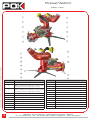
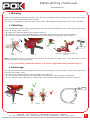
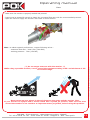
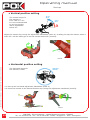
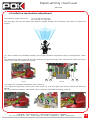
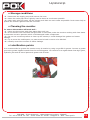
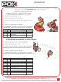
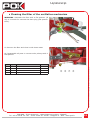
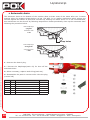
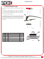
User manual
FIREFIGHTING EQUIPMENT
KATZ
DOC 1973 EN Rev.A - 10/09/13
POK SAS - ZI Les Guignons - 10400 Nogent-sur-Seine - FRANCE
Tel : 03 25 39 84 78 - Fax : 03 25 39 84 90 - Email : [email protected] - Web : www.pok.fr
Identification
DESCRIPTION
VALUE
Product type
Monitor
Product
Portable monitor "KATZ"
Product reference concerned by the manual
Ref. : 31989
Ref. 31989 and 32741 used for all visuals
1973
Language
English
Creation date
10/09/2013
Modification date
10/09/2013
Review follow up
Rev. A - 10/09/13 :
- Original file
DOC 1973 EN Rev.A - 10/09/2013 - Copyright© POK SAS - Illustrations are only informative
Documentation ref.
2
POK SAS - ZI Les Guignons - 10400 Nogent-sur-Seine - FRANCE
Tel : 03 25 39 84 78 - Fax : 03 25 39 84 90 - Email : [email protected] - Web : www.pok.fr
Table of contents
POK SAS - ZI Les Guignons - 10400 Nogent-sur-Seine - FRANCE
Tel : 03 25 39 84 78 - Fax : 03 25 39 84 90 - Email : [email protected] - Web : www.pok.fr
DOC 1973 EN Rev.A - 10/09/2013 - Copyright© POK SAS - Illustrations are only informative
IDENTIFICATION........................................................................................................2
TABLE OF CONTENTS..................................................................................................3
INSTRUCTIONS...........................................................................................................4
• Introduction....................................................................................................4
• Dismantling and warranty.................................................................................4
• Use...............................................................................................................5
• Limits of use...................................................................................................5
PRESENTATION..........................................................................................................6
MAIN VIEW...........................................................................................................6
CHARACTERISTICS................................................................................................7
• Construction...................................................................................................7
• Characteristics................................................................................................7
OVERALL DIMENSIONS...........................................................................................8
OPERATING MANUAL..................................................................................................9
INSTALLATION.......................................................................................................9
• Warning.........................................................................................................9
• Unfolding.......................................................................................................9
• Anchorage......................................................................................................9
• Initialization.................................................................................................. 10
• Connecting................................................................................................... 10
USE................................................................................................................... 11
SETUP................................................................................................................ 12
• Vertical position setting.................................................................................. 12
• Horizontal position setting ............................................................................. 12
• Oscillation mechanism setting......................................................................... 13
• Anti-tip over mechanism................................................................................. 14
UPKEEP..................................................................................................................... 15
• Storage conditions......................................................................................... 15
• Cleaning the monitor..................................................................................... 15
• Lubrification points........................................................................................ 15
• Restoring to operational................................................................................. 16
• Spare parts.................................................................................................. 16
• Changing the gasket of outlet.......................................................................... 17
• Changing the gaskets of inlet flange................................................................. 17
• Changing the gaskets of safety mechanism....................................................... 18
• Cleaning the filter of the oscillation mechanism ................................................. 19
• Automatic drain............................................................................................. 20
• Dismantling the legs ..................................................................................... 21
BILL OF MATERIALS.................................................................................................. 22
MIDDLE PIPE AND SWIVEL PIPE............................................................................. 22
• Exploded view............................................................................................... 22
• Parts list....................................................................................................... 23
BODY AND SWIVEL PIPE ...................................................................................... 24
• Exploded view............................................................................................... 24
• Parts list....................................................................................................... 25
INLET FLANGE AND LEGS..................................................................................... 26
• Exploded view............................................................................................... 26
• Parts list....................................................................................................... 27
NOTES...................................................................................................................... 28
3
Instructions
• Introduction
Please read this manual before using the equipment.
Use, maintenance, or any other operation of the equipment must be done by staff trained for the use of this
equipment and aware of the safety rules.
While using the monitor (use, maintenance, installation, ...) it is important to wear a personal protective
equipment.
• Dismantling and warranty
This equipment has a warranty of 1 year for any fabrication default, excepted special written agreement.
The exploded view and bill of materials are not a dismantling manual.
Any dismantling or maintenance operation of the device must be done with water supply turned off.
Dismantling and/or modification of the equipment outside POK SAS factory is allowed only in compliance
with procedure described in this manual, and therefore does not affect the warranty.
If the equipment is repaired, the spare parts must be supplied by POK SAS. If not, technical characteristics
listed in this document won’t be valid, the warranty will void and POK SAS responsability will not apply.
DOC 1973 EN Rev.A - 10/09/2013 - Copyright© POK SAS - Illustrations are only informative
If maintenance operation damage parts, the warranty may not work if the procedure has not been carried
out properly.
Although this is not explicitly stated in instructions, use and wear of protective equipment are obligatory
during maintenance operation. POK SAS cannot be responsible of any damage or accident which may occur
during the dismantling. If this obligation is not met, please refer to the tools instructions guides for more
details.
Only POK SAS can ensure proper and safe functioning of the equipment. Therefore POK SAS will not be liable
for any damage or accident caused by dismantling of the equipment outside its workshop.
Do not modify the equipment, it may not be working or be dangerous for use.
4
POK SAS - ZI Les Guignons - 10400 Nogent-sur-Seine - FRANCE
Tel : 03 25 39 84 78 - Fax : 03 25 39 84 90 - Email : [email protected] - Web : www.pok.fr
Instructions
• Use
Please respect the technical limits of the equipment.
The apparatus can not be used if any part is missing or damaged.
During its use, the montior must be securetly fastened to a fix ground anchorage with supplied strap.
Failure to follow these instructions could result in serious injury and/or damage the monitor.
(reaction force : about 250 Kgs for 3000 l/min at 7 bar to the exit).
Never stand in front of the monitor or point somebody with monitor. It can cause death.
Do not point with monitor at a aera between the pump and the monitor’s inlet.
Do not exceed the maximum setting of 85° and minimum of 35° for vertical range.
Please note that use of the monitor may damage the tarjet. Ensure the aera is secure before use.
It is important to know and respect the security rules regarding your operating environnement.
It is recommanded not to use the monitor with emulsifier.
After use with emulsifier, clean the monitor with clean water under pressure to remove impurities from the
oscillation mechanism.
The recommended work pressure is 7 bar (100 PSI). The efficiency over this pressure is not guarantee.
Unrespect of safety instructions and use of the monitor over the recommended pressure can be dangerous
and even cause death.
POK SAS is not responsible of any accident that may occur during operation caused by improper use or noncompliance with safety requirements.
• Limits of use
POK SAS guarantee monitor for a maximum operating pressure of 16 bar (230 PSI) when the oscillation
mechanism is off, 12 bar (170 PSI) when it is on .
POK SAS guarantee monitor for a maximum test pressure of 25,5 bar (370 PSI) in closed position.
Without POK written authorization, warranty will void if the equipment is used with pressure over the
specified one in this document.
POK SAS - ZI Les Guignons - 10400 Nogent-sur-Seine - FRANCE
Tel : 03 25 39 84 78 - Fax : 03 25 39 84 90 - Email : [email protected] - Web : www.pok.fr
5
DOC 1973 EN Rev.A - 10/09/2013 - Copyright© POK SAS - Illustrations are only informative
Do not use the monitor over 16 bar (230 PSI) when the oscillation is off and over 12 bar (170 PSI) when the
oscillation is on. The equipment can be damaged over these pressures.
Presentation
DOC 1973 EN Rev.A - 10/09/2013 - Copyright© POK SAS - Illustrations are only informative
Main view
MARK
1
2
3
6
DESIGNATION
MARK
DESIGNATION
Body with oscillation mechanism
12
Vertical adjustment handwheel
Outlet FM 2.5" NH
13
Horizontal adjustment mobile handwheel
14
Legs
15
Tungsten pin
16
Anchoring ring
17
Stand of safety mechanism
18
Vertical adjustment stopper
19
Leg unlock pin
20
Safety mechanism pin
21
Automatic drain
22
Drain filter
23
Horizontal adjustment axis
24
Pressure gauge
Note : a coupling can be supplied on request, consult
our catalog for more information about coupling.
Inlet flange FM G 4" B
Note : a coupling can be supplied on request, consult
our catalog for more information about coupling.
4
Carrying handle
5
Left travel adjustment
6
Left speed adjustment
7
Right speed adjustment
8
Right travel adjustment
9
Oscillation mechanism valve
10
Shutoff handle
11
Greasers
POK SAS - ZI Les Guignons - 10400 Nogent-sur-Seine - FRANCE
Tel : 03 25 39 84 78 - Fax : 03 25 39 84 90 - Email : [email protected] - Web : www.pok.fr
Presentation
Characteristics
• Construction
DESCRIPTION
VALUE
Body
• Aluminium alloy.
• Coating : polyester.
leg pin
• Tungsten carbide
Pins and screws
• Stainless steel.
• Characteristics
DESCRIPTION
VALUE
• 3000 l/min @ 7 bar (790 GPM @ 100 PSI)
Working pressure
• 16 bar (230 PSI)
Inlet
• G 4" B
Outlet
• 2,5" NH
Vertical range
• 0º to +85º
Horizontal range
• 360º
Automatic oscillation
• -25º to +25º maximum
Removable pipe
• No
Safety
• Locking pin for legs
• Locking pin for vertical adjustment
• Anti-tip over mechanism
DOC 1973 EN Rev.A - 10/09/2013 - Copyright© POK SAS - Illustrations are only informative
Maximum flow rate
POK SAS - ZI Les Guignons - 10400 Nogent-sur-Seine - FRANCE
Tel : 03 25 39 84 78 - Fax : 03 25 39 84 90 - Email : [email protected] - Web : www.pok.fr
7
Presentation
Overall dimensions
518 mm
627 mm
524 mm
DOC 1973 EN Rev.A - 10/09/2013 - Copyright© POK SAS - Illustrations are only informative
mini
mini
170
134
max
170
134
max
148 mm
463 mm
428 mm
397 mm
506 mm
8
POK SAS - ZI Les Guignons - 10400 Nogent-sur-Seine - FRANCE
Tel : 03 25 39 84 78 - Fax : 03 25 39 84 90 - Email : [email protected] - Web : www.pok.fr
463 mm
326 mm
14
6
m
m
370 mm
Operating manual
Installation
• Warning
Read these operating instructions before use. The non-compliance with operating instructions may lead to
injuries or may cause damage to the monitor.
The monitor is designed to operate with a 3000 l/min (790 GPM) maximum flow rate at 7 bar (100 PSI).
• Unfolding
- 1 - Maintain the monitor with carrying handle and fold out retractable legs. Pull a front leg to open others
until it locks into place (mark A).
- 2 - Make sure that the safety pin is locked (mark B).
- 3 - Place the unit on a firm and flat ground, each leg’s pin should touch the ground (mark C).
- 4 - Screw or unscrew the safety mechanism’s stand to adjust to the ground level (mark C).
Mark A
Mark B
Mark C
Note : leg’s pin must lay on solid and firm ground. The monitor can slide, slip or even take-off in case of
soft ground (sand, mud, gravel, etc).
• Anchorage
The montior must be securetly fastened to a fix ground anchorage (a drived stake, a solid anchorage on the
ground or the supply hose).
- 1 - Fasten the supplied strap to the anchorage ring (mark A).
- 2 - The monitor, the target and the anchorage must be on the same straight line(mark B).
- 3 - The monitor can be fastened to supply hose if you haven’t available base to secure it (mark C)
Pompe
Mark A
Mark B
Mark C
POK SAS - ZI Les Guignons - 10400 Nogent-sur-Seine - FRANCE
Tel : 03 25 39 84 78 - Fax : 03 25 39 84 90 - Email : [email protected] - Web : www.pok.fr
9
DOC 1973 EN Rev.A - 10/09/2013 - Copyright© POK SAS - Illustrations are only informative
/!\ For your safety, fasten the monitor to a secure support with the provided strap /!\
Operating manual
Installation
• Initialization
Respect the following instructions before connecting the monitor to water supply.
- 1 - Point up the outlet pipe by turning the vertical adjustment handwheel untill the ‘‘CLICK’’ (mark A).
- 2 - Set up the horizontal adjustment handwheel (mark B) and adjust the outlet pipe on horizontal range
(mark C).
Mark A
Mark B
Mark C
- 3 - Remove the safety pin of the anti-tip over mechanism (Mark D).
- 4 - Turn off the oscillation mechanism valve (vertical position - Mark E).
Mark E
• Connecting
- 1 - Connect the diffuser or the branchpipe (not supplied) to the outlet coupling (mark A).
- 2 - Connect the supply hose to the inlet coupling. Please, make sure you have at least 5 meters of straight
hose at the monitor’s inlet (mark B).
5 m mini
0m
R2
i
mi n
DOC 1973 EN Rev.A - 10/09/2013 - Copyright© POK SAS - Illustrations are only informative
Mark D
Mark A
Mark B
5 m mini
3m
10
POK SAS - ZI Les Guignons - 10400 Nogent-sur-Seine - FRANCE
Tel : 03 25 39 84 78 - Fax : 03 25 39 84 90 - Email : [email protected] - Web : www.pok.fr
Operating manual
Use
- Make sure the monitor is properly settled and pointed.
- Pump must be powerfull enough to obtain the requested flow rate with the recommended pressure.
- Open the valve to supply the monitor with water or foam solution.
/!\ Do not target someone with the monitor /!\
While using a portable monitor, nerver exceed the maximum setting of 85° and minimum of 35°
for vertical range.
35°
Never target an area placed in the axis between the pump and the monitor inlet.
If your monitor is equiped with a nozzle which has a spread jet position, make sure the area
around the monitor is not sensitive to important water projection, before using this position.
POK SAS - ZI Les Guignons - 10400 Nogent-sur-Seine - FRANCE
Tel : 03 25 39 84 78 - Fax : 03 25 39 84 90 - Email : [email protected] - Web : www.pok.fr
11
DOC 1973 EN Rev.A - 10/09/2013 - Copyright© POK SAS - Illustrations are only informative
Note : to obtain optimal performance, respect following values :
- maximum flow rate : 3000 l/min (790 GPM)
- working pressure : 7 bar (100 PSI)
Operating manual
Setup
• Vertical position setting
85°
The vertical range for
this monitor is
from +85° to +35°.
It is not recommanded
to use the monitor
with a adjustment
below 35°.
35°
Adjust the monitor by turning the adjustment handwheel (mark A). A safety pin stop the monitor when it
reach 35°. Pull the safety pin to set the monitor below 35° (mark B).
Mark A
Mark B
DOC 1973 EN Rev.A - 10/09/2013 - Copyright© POK SAS - Illustrations are only informative
• Horizontal position setting
The horizontal range for
this monitor is 360°.
360°
- 1 - Set up the horizontal adjustment handwheel (mark A).
- 2 - Point the monitor to the desired direction by turning the adjustment handwheel (mark B).
Mark A
12
Mark B
POK SAS - ZI Les Guignons - 10400 Nogent-sur-Seine - FRANCE
Tel : 03 25 39 84 78 - Fax : 03 25 39 84 90 - Email : [email protected] - Web : www.pok.fr
Operating manual
Setup
• Oscillation mechanism adjustment
The following angles can be set : 15° and 25° for left side.
15° and 25° for right side.
Left and right side can be setted with different angles. Respect the following instructions to adjust the
monitor.
25°
25°
15° 15°
Mark A
25°
15°
Mark B
15°
25°
- 3 - Open the oscillation mechanism valve (Mark C).
- 4 - Adjust the speed by turning rear knobs (mark D). Left and right sides can be setted with different
speeds.
- 5 - Turn off the oscillation mechanism valve to stop the automatic sweeping (mark E).
Mark C
Mark D
Mark E
POK SAS - ZI Les Guignons - 10400 Nogent-sur-Seine - FRANCE
Tel : 03 25 39 84 78 - Fax : 03 25 39 84 90 - Email : [email protected] - Web : www.pok.fr
13
DOC 1973 EN Rev.A - 10/09/2013 - Copyright© POK SAS - Illustrations are only informative
- 1 - Prior to define the oscillation settings, turn off the oscillation mechanism valve (vertical position - Mark
E).
- 2 - Adjust bump stop on the left and right sides by turning front knobs. Take care to screw knobs on correct
holes, at 15° and 25° positions (mark B).
Operating manual
Setup
• "Anti-tip over" mechanism
A safety feature will turn off the water supply as soon as the monitor lift from the ground.
Adjust the stand to the ground level when the monitor is in order (mark A). Remove the safety pin, this will
activate the the "anti-tip over" mechanism (mark B). Lower the valve to supply water (mark C). The monitor
must be plugged to a pump. If the safety pin is not removed, the "anti-tip over" mechanism won’t work.
Mark A
Mark B
Mark C
/!\ The monitor should not be used with the safety pin engaged /!\
DOC 1973 EN Rev.A - 10/09/2013 - Copyright© POK SAS - Illustrations are only informative
Operating principle : if the monitor lift from the ground (Rep. A), the stand getting away from the ground
(Rep. B). By sliding downwards, the stand trigger the automatic valve (Rep. C) which activate a hydraulic
jack (Rep. D). The hydraulic jack close smoothly the supply valve in return (Rep. E).
A
E
C
D
B
With main valve closed, the monitor is stopped. You can identify and solve the issue (for example : stream
pointed downwards, ground too soft...). Set the monitor properly, arm the safety mechanism with the pump
fully closed and open once again the main valve.
/!\ During the reset process, the supply pump must be shut off. Open the monitor’s main valve
before starting-up the pump /!\
14
POK SAS - ZI Les Guignons - 10400 Nogent-sur-Seine - FRANCE
Tel : 03 25 39 84 78 - Fax : 03 25 39 84 90 - Email : [email protected] - Web : www.pok.fr
Upkeep
• Storage conditions
- 1 - Disconnect the supply pump and remove the hose.
- 2 - Move the outlet pipe left to right by hand to drain as much water possible.
- 3 - With main valve full open, tilt the monitor and drain as much water as possible. Drain water help to
protect the monitor against frost and corrosion.
• Cleaning the monitor
To ensure the monitor will work well :
- 1 - Clean up the monitor with clear water after each use.
- 2 - If the monitor was used with charged water or sea water, make the monitor working with clear water
to evacuate corrosive particles which could damaged inside components.
- 3 - Do not use corrosive product to clean up the monitor, it could damaged the gasket and create
leakage.
- 4 - Try to move the mobile parts, no parts must be hard to move or be blocked.
- 5 - Visually control the monitor to detect leakage.
• Lubrification points
DOC 1973 EN Rev.A - 10/09/2013 - Copyright© POK SAS - Illustrations are only informative
It is recommended to grease the monitor every 6 months by using a type EP 02 grease. Connect a grease
gun to the grease nipples located close the swivelling parts. You can also on a regular basis clean leg’s gears,
hydraulic jack and all swivel parts and grease with a brush.
POK SAS - ZI Les Guignons - 10400 Nogent-sur-Seine - FRANCE
Tel : 03 25 39 84 78 - Fax : 03 25 39 84 90 - Email : [email protected] - Web : www.pok.fr
15
Upkeep
• Restoring to operational
You must do this procedure before putting back your equipment into service :
- 1 - Make sure not parts are missing or damaged.
- 2 - Connect a hose at the inlet / connect to the flange.
- 3 - Put a cap with a air vent valve on the outlet thread.
- 4 - Test the monitor, increase slowly the pressure up to 16 bar (235 PSI) when using without oscillating
device, to 12 bar when using with oscillating device, then look for eventual leakage.
- 5 - Put a nozzle on the outlet thread.
- 6 - Test the monitor in normal use conditions with a pressure of 7 bar. Make sure every parts move as they
should, nothing must block. This must last 10 min.
If no problem have been encountered, the monitor may be put back into service.
• Spare parts
Some parts as gaskets may need to be changed more often depending on the use and storage conditions.
Please contact our sales department to get information about after sales service, or to obtain spare parts.
Use the bill of materials in this document to identify the spare parts you need.
DOC 1973 EN Rev.A - 10/09/2013 - Copyright© POK SAS - Illustrations are only informative
Note : The serial number of the monitor may be required to know your eligibility to warranty.
16
POK SAS - ZI Les Guignons - 10400 Nogent-sur-Seine - FRANCE
Tel : 03 25 39 84 78 - Fax : 03 25 39 84 90 - Email : [email protected] - Web : www.pok.fr
Upkeep
/!\ WARNING /!\
Maintenance operation of the device must be done with water
supply turn off and system draine.
• Changing the gasket of outlet
1 - Unscrew 12 screws (mark. 31)
2 - Separate the outlet from the body.
3 - Remove the O’ring (mark 29) and replace by a new
one.
4 - Grease the gasket before installing.
5 - Reassemble all parts in reverse order. The screws
must be glued (Loctite 243) and tightened in a crooswise.
MARK
QTY
DESCRIPTION
REF
23
1
Swivel pipe
25495
29
1
Gasket Ø89 x Ø4
-
30
12
Washer W6
-
31
12
Screw CHC M 6-25
-
• Changing the gaskets of inlet flange
1 - Unscrew the banjo bolt from the inlet flange.
2 - Unscrew 4 screws (mark. 59).
DOC 1973 EN Rev.A - 10/09/2013 - Copyright© POK SAS - Illustrations are only informative
3 - Remove the inlet flange, the ball valve’s flat gasket
and 4 O’ring. Take care not to scratch sealing surfaces.
4 - Grease the gasket before installing.
5 - Reassemble the parts in reverse order. The screws
must be glued (Loctite 243) and tightened in a crooswise.
MARK
QTY
DESCRIPTION
REF
40
1
Body with oscillation mechanism
-
56
1
Inlet flange
27245
51
1
Flexible hose - length 200
-
49
1
Gasket Ø85,32 x Ø3,53
-
46
1
Gasket Ø86 x Ø2
-
48
1
Gasket Ø94 x Ø2
-
47
1
Gasket Ø102 x Ø2
-
58
1
Washer W10
-
59
1
Screw CHC M10
-
79
1
Ball valve’s flat gasket
31997
POK SAS - ZI Les Guignons - 10400 Nogent-sur-Seine - FRANCE
Tel : 03 25 39 84 78 - Fax : 03 25 39 84 90 - Email : [email protected] - Web : www.pok.fr
17
Upkeep
• Changing the safety mechanism’s gaskets
1 - Remove the pin’s ring (mark 52) and the safety pin
(mark 54).
2 - Unscrew the stop (mark 53) from the safety axis.
3 - Unscrew the spring’s seat (mark 55) from the inlet
flange.
4 - Slide downwards the safety axis (mark 64) and
remove 2 O’rings (mark 61)
5 - Remove O’ring (mark 62) from the circular groove by
using a thin screwdriver. Take care not to scratch sealing
surfaces.
6 - Grease all gaskets and safety axis and reassemble all
parts in reverse order. Take care all parts slide smoothly.
MARK
QTY
DESIGNATION
REF
1
Pin’s ring
-
53
1
Stop
27254
54
1
Safety pin
-
55
1
Spring’s seat
27249
61
2
Gasket Ø15,6 x 2,4
62
1
Gasket Ø19,6 x 2.4
64
1
Safety axis
DOC 1973 EN Rev.A - 10/09/2013 - Copyright© POK SAS - Illustrations are only informative
52
18
POK SAS - ZI Les Guignons - 10400 Nogent-sur-Seine - FRANCE
Tel : 03 25 39 84 78 - Fax : 03 25 39 84 90 - Email : [email protected] - Web : www.pok.fr
Upkeep
• Cleaning the filter of the oscillation mechanism
WARNING : Maintain the filter with a flat spanner (Ø
25) or a wrench for unscrew the drain plug (flat spanner
Ø 20).
1 - Remove the filter and clean it with clean water.
2 - Reassemble all parts in reverse order, always with 2
flat spanner.
QTY
DESIGNATION
REF
40
1
Body with oscillation mechanism
-
37
1
Drain’s strainer
-
38
1
Washer
-
39
1
Plug
-
POK SAS - ZI Les Guignons - 10400 Nogent-sur-Seine - FRANCE
Tel : 03 25 39 84 78 - Fax : 03 25 39 84 90 - Email : [email protected] - Web : www.pok.fr
DOC 1973 EN Rev.A - 10/09/2013 - Copyright© POK SAS - Illustrations are only informative
MARK
19
Upkeep
• Automatic drain
The automatic drain at the bottom of the monitor allow to drain most of the water after use. It starts
draining when the pressure drops below 0,4 bar (5.8 PSI). It is a safety mechanism which protect the
monitor against the effects of frost and corrosion by draining the water. Even if it is not recommended,
this mechanism can be shut off by following steps below. Please periodically clean up the automatic drain
following the procedure below.
Drain diaphragm
upwards
=
automatic drain
is ON
43
Weep holes
Drain diaphragm
downwards
=
automatic drain
is OFF
43
DOC 1973 EN Rev.A - 10/09/2013 - Copyright© POK SAS - Illustrations are only informative
1 - Unscrew the drain’s plug.
2 - Reverse the diaphragm(mark 43) for shut off the
automatic drain.
3 - When necessary, replace used O’ring(mark 44).
4 - Reassemble the parts in reverse order. Glue the plug
(Loctite 243)
MARK
QTY
DESIGNATION
REF
40
1
Body with oscillation mechanism
-
41
1
Screw CBHC M6
-
42
1
Washer L6
-
43
1
Automatic drain’s diaphragm
-
44
1
Washer Ø40xØ2,5
-
45
1
Automatic drain’s plug
-
20
POK SAS - ZI Les Guignons - 10400 Nogent-sur-Seine - FRANCE
Tel : 03 25 39 84 78 - Fax : 03 25 39 84 90 - Email : [email protected] - Web : www.pok.fr
Upkeep
• Dismantling the legs
1 - Unscrew 5 screws (mark 77) and remove the bottom
plate.
2 - Remove nylon washers, rear legs, nylon washers,
front legs and spring washers. To avoid any confusion,
the front right leg is engraved with letter "D" (mark A).
3 - Clean and grease all parts.
D
4 - Reassemble all parts in reverse order. Take care all
parts slide smoothly and to reassemble spring washers
following the picture (mark. B). The screws of the bottom
plate must be glued (Loctite 243) and tightened in a
crooswise.
Mark. A
70
QTY
DESIGNATION
REF
12
Spring washer CL 20,4 - 36 - 1,3
71
1
Front left leg
-
72
1
Front right leg
-
74
1
Rear leg
-
76
1
Bottom plate
-
77
5
Screw FHC M 8-16
75
6
Nylon washer
Mark. B
POK SAS - ZI Les Guignons - 10400 Nogent-sur-Seine - FRANCE
Tel : 03 25 39 84 78 - Fax : 03 25 39 84 90 - Email : [email protected] - Web : www.pok.fr
DOC 1973 EN Rev.A - 10/09/2013 - Copyright© POK SAS - Illustrations are only informative
MARK
70
75
21
Bill of materials
Middle pipe and swivel pipe
DOC 1973 EN Rev.A - 10/09/2013 - Copyright© POK SAS - Illustrations are only informative
• Exploded view
22
POK SAS - ZI Les Guignons - 10400 Nogent-sur-Seine - FRANCE
Tel : 03 25 39 84 78 - Fax : 03 25 39 84 90 - Email : [email protected] - Web : www.pok.fr
Bill of materials
Middle pipe and swivel pipe
• Parts list
MARK
QTY
DESCRIPTION
REF
1
1
Middle pipe
2
2
Gasket Ø 31,47 x Ø 1,78
24598
3
2
Bearing
4
8
Washer W6
-
5
8
Screw CHC M6-20
-
6
2
Screw STHC PL M8
-
7
1
O’ring N°43
-
8
80
Ball Ø 6,35
9
1
Cylindrical worm wheel
10
1
Gasket Ø91x Ø3
11
1
Swivel pipe with pressure gauge
12
1
Stopper
-
13
1
Screw CBHC M6
-
14
1
Handwheel Ø90
27419
15
1
Screw FHC M6
-
16
1
Folding handle
-
17
2
Worm’s bearing
28353
18
2
O’ring N°12
-
19
2
O’ring N°14
-
20
4
Internal and external washer for ball bearing
-
21
2
Ball cage
-
22
1
Worm
17785
24597
24600
DOC 1973 EN Rev.A - 10/09/2013 - Copyright© POK SAS - Illustrations are only informative
24611
POK SAS - ZI Les Guignons - 10400 Nogent-sur-Seine - FRANCE
Tel : 03 25 39 84 78 - Fax : 03 25 39 84 90 - Email : [email protected] - Web : www.pok.fr
23
Bill of materials
Body and swivel pipe
DOC 1973 EN Rev.A - 10/09/2013 - Copyright© POK SAS - Illustrations are only informative
• Exploded view
24
POK SAS - ZI Les Guignons - 10400 Nogent-sur-Seine - FRANCE
Tel : 03 25 39 84 78 - Fax : 03 25 39 84 90 - Email : [email protected] - Web : www.pok.fr
Bill of materials
Body and swivel pipe
• Parts list
QTY
DESCRIPTION
REF
1
1
Middle pipe
13
1
Screw CBHC M6
-
14
1
Handwheel Ø90
27419
15
1
Screw FHC M6
-
16
1
Folding handle
-
23
1
Swivel pipe
24
1
Carrying handle’s bracket
25
2
Screw CHC M8
-
26
1
Carrying handle
-
27
1
Screw CHC M10
-
28
1
Handwheel’s axis
33233
29
1
Gasket Ø89 x Ø4
-
30
12
Washer W6
-
31
12
Screw CHC M6
-
32
1
Cylindrical worm wheel
33
1
Gasket Ø91x Ø3
-
34
80
Ball Ø 6,35
-
35
1
O’ring N°43
-
36
2
Screw STHC PL M8
-
37
1
Drain’s strainer
-
38
1
Washer
-
39
1
Plug
-
40
1
Body with oscillation mechanism
-
41
1
Screw CBHC M6
-
42
1
Washer L6
-
43
1
Automatic drain’s diaphragm
44
1
Washer Ø40xØ2,5
45
1
Automatic drain’s plug
POK SAS - ZI Les Guignons - 10400 Nogent-sur-Seine - FRANCE
Tel : 03 25 39 84 78 - Fax : 03 25 39 84 90 - Email : [email protected] - Web : www.pok.fr
24598
10925
31999
DOC 1973 EN Rev.A - 10/09/2013 - Copyright© POK SAS - Illustrations are only informative
MARK
10843
10842
25
Bill of materials
Inlet flange and legs
DOC 1973 EN Rev.A - 10/09/2013 - Copyright© POK SAS - Illustrations are only informative
• Exploded view
26
POK SAS - ZI Les Guignons - 10400 Nogent-sur-Seine - FRANCE
Tel : 03 25 39 84 78 - Fax : 03 25 39 84 90 - Email : [email protected] - Web : www.pok.fr
Bill of materials
Inlet flange and legs
• Parts list
QTY
DESCRIPTION
REF
40
1
Body oscillation mechanism
-
46
1
Gasket Ø86 x Ø2
-
47
1
Gasket Ø102 x Ø2
-
48
1
Gasket Ø94 x Ø2
-
49
1
Gasket Ø85,32 x Ø3,53
-
50
2
Hose clamp
-
51
1
Flexible hose - length 200
-
52
1
Pin’s ring
-
53
1
Stop
54
1
Safety pin
55
1
Spring’s seat
27249
56
1
Inlet flange
31995
57
1
Screw STHC PL M8
-
58
4
Washer W10
-
59
4
Screw CHC M10
-
60
1
Safety spring
61
2
Gasket Ø15,6 x 2,4
-
62
1
Gasket Ø19,6 x 2.4
-
64
1
Safety axis
27251
65
1
Standing nut
27252
66
1
Foot’s screw
27253
67
1
Foot
27256
68
1
Washer L4
-
69
1
Screw RLS M4
-
70
12
Spring washer CL 20,4 - 36 - 1,3
-
71
1
Front left leg
17972
72
1
Front right leg
17971
73
2
Driving pin
20213
74
2
Rear leg
17973
75
6
Nylon washer
10916
76
1
Bottom plate
10866
77
5
Screw FHC M 8-16
78
4
Leg’s pin
17988
79
1
Ball valve’s flat gasket
31997
POK SAS - ZI Les Guignons - 10400 Nogent-sur-Seine - FRANCE
Tel : 03 25 39 84 78 - Fax : 03 25 39 84 90 - Email : [email protected] - Web : www.pok.fr
27254
-
27250
DOC 1973 EN Rev.A - 10/09/2013 - Copyright© POK SAS - Illustrations are only informative
MARK
-
27
DOC 1973 EN Rev.A - 10/09/2013 - Copyright© POK SAS - Illustrations are only informative
Notes
28
POK SAS - ZI Les Guignons - 10400 Nogent-sur-Seine - FRANCE
Tel : 03 25 39 84 78 - Fax : 03 25 39 84 90 - Email : [email protected] - Web : www.pok.fr