1
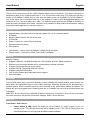
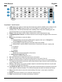
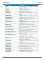
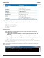
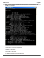
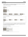
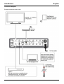
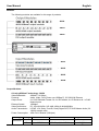
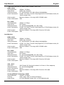
Modular Matrix Range User Manual Eng lis h No. 38250, 38251, 38252, 38253, 38254, 38255, 38256, 38257, 38259 www.lindy.com Tested to Comply with FCC Standards For Home and Office Use! © LINDY ELECTRONICS LIMITED & LINDY-ELEKTRONIK GMBH - FIRST EDITION (April 2015) User Manual English Introduction Thank you for purchasing from the LINDY Modular Matrix range of products. This range of products is designed to allow you to create a matrix with 8, 16 or 32 input and output ports. The input ports can be a choice of C6 HDBaseT, HDMI, DVI or VGA while the output ports can be HDMI, DVI or C6 HDBaseT. Any of the inputs can be combined with any of the outputs to create a UHD 4Kx2K@30Hz display over distances of up to 70m and 1080p up to 100m. The modular design provides the ultimate in flexibility for audio and video distribution as a matrix, convertor or an extender in retail product demonstration, training and public display application in schools, pubs etc. Package Contents Modular Matrix (including control board) with spaces for 2, 4 or 8 modular boards IR Blaster Blanking plates fitted to the rear of the units IR Extender Power Cord (2x for 16 and 32 port Chassis) Remote control inc battery User manual Input boards – choose from C6 HDBaseT, HDMI, DVI-D and VGA Output boards – choose from HDMI, DVI-D and C6 HDBaseT Features Modular Chassis Supports HDMI 4K, C6 HDMI Extender 4K, VGA WUXGA and DVI 1080p resolutions Modular input and output boards can be mixed between multiple interfaces Supports Audio pass-through on all boards Supports RS232, Telnet and Web GUI controls Supports multiple EDID modes 16 & 32 port models have redundant power supplies Rack Mountable Installation Your modular matrix may need some assembly, before installing the modular boards please ensure you have taken the appropriate steps to avoid static discharge. Assembly should only be attempted by a qualified person and the chassis should not be connected to the power when adding the boards. The boards are not hot pluggable and if further boards are to be added, the unit must be powered down and unplugged. Make sure all your devices are switched off before making any connections. Once all the connections are made, switch on the devices in this order: displays, Matrix, source devices. Operation Front Panel – 8x8 Version 1. Power Button & LED: Press this button to turn the Matrix on, press it again to put it in standby mode. The LED will illuminate red in standby mode. If the LED is flashing then the internal temperature is too high and the Matrix needs ventilation. User Manual English 2. 3. LCM: Displays the status of each input and output plus options available when in Menu mode. Lock Button & LED: Press this button to lock all the function buttons on the panel, press and hold it again to unlock the buttons. The LED will illuminate red when the buttons are locked. 4. Return: Press this button while in Menu mode and you will be taken back a step. 5. Menu: Press this button to enter the Menu: 1. EDID: a. Standard EDID: use the built in EDID which supports video up to 1080p@60Hz / WUXGA@60RB and Audio LPCM 2CH. b. Dynamic EDID: Copies the first connected output device EDID. c. Manual EDID: Uses the EDID of each device connected to the input / output ports. 2. IP: a. IP address b. Netmask c. Gateway 3. Temperature: a. Temperature 1 b. Temperature 2, shows the internal temperature of the device. 4. LCM Contrast range from 1-4 6. Left/Right Arrows: Use these buttons to scroll through the pages while in the menu mode. 7. Save: Press this button to save the current setting of the Input / output ports (8 positions available). 8. Recall: This button will allow you to recall the saved pre-sets. 9. Enter: Press this button to confirm the setting or selection. 10. All: Press all, then the input port then enter to display the same signal on all ports. 11. Out/In: Use these buttons to select the input source you want to show on an output/display. The sequence should be to select the output ports (display) from the top row of buttons, then select the input source device. 12. 1-8: The numbers relate to the input and output ports on the rear of the unit. Rear Panel Note: the example below shows an 8x8 matrix fitted with HDMI input and HDMI output boards. 1. 2. Output 1-8: Connect your display devices to the output ports. Central CPU Board: (with the following connections) a. IR In: Extend your IR receiver port using the included IR receiver. User Manual 3. 4. 5. English b. RS-232: Connect a D-Sub 9 pin cable from a PC/Laptop for RS232 control of the Matrix or connected devices. c. Control: Connect an active network cable for Telnet/Web GUI control. d. IR All Out/In: Reserved. e. Service: This port is reserved for firmware update only. f. Output 0: This port is not activated. Input 1-8: Connect your source devices to the input ports on the lower part of the unit. Power: The device will automatically turn on when the power cable is connected. Ventilation fan: The fan will be active when the device is switched on. The vent must not be blocked or covered and must have adequate space to allow ventilation. Front Panel – 16x16 Version 1. 2. 3. 4. 5. 6. 7. 8. 9. LCM: Displays the status of each input and output plus options available when in Menu mode. IR Window: Receives the signal from your infrared remote control Power Button & LED: Press this button to turn the Matrix on, press it again to put it in standby mode. The LED will illuminate red in standby mode. If the LED is flashing then the internal temperature is too high and the Matrix needs ventilation. Left/Right/Up/Down Arrows: Use these buttons to scroll through the pages while in the menu mode. Return: Press this button while in Menu mode and you will be taken back a step. Menu: Press this button to enter the Menu: 1. EDID: a. Standard EDID: use the built in EDID which supports video up to 1080p@60Hz / WUXGA@60RB and Audio LPCM 2CH. b. Dynamic EDID: Copies the first connected output device EDID. c. Manual EDID: Uses the EDID of each device connected to the input / output ports. 2. IP: a. IP address b. Netmask c. Gateway 3. Temperature: Shows the internal temperature of the device. 5. LCM Contrast range from 1-4 Adjust the LCM contrast from 1 to 4 All: Press this button to assign the same input to all outputs Out/In: Use these buttons to select the input source you want to show on an output/display. The sequence should be to select the out/in button then the input, then the out/in and then the output, finally select enter. 1-9: The numbers relate to the input and output ports on the rear of the unit. User Manual English 10. Plus (+): This allows you to select multiple outputs for a selected input and can only be used in conjunction with the OUT/IN button. 11. Lock Button & LED: Press this button to lock all the function buttons on the panel, press and hold it again to unlock the buttons. The LED will illuminate red when the buttons are locked. 12. Save: Press this button to save the current setting of the Input / output ports (8 positions available). 13. Recall: This button will allow you to recall the saved pre-sets. 14. Enter: Press this button to confirm the setting or selection. Rear Panel Note: the example below shows a 16x16 matrix fitted with HDMI input and HDMI output boards. 1. 2. 3. 4. 5. Output 1-16: Connect your display devices to the output ports. Central CPU Board: (with the following connections) a. IR In: Extend your IR receiver port using the included IR receiver. b. RS-232: Connect a D-Sub 9 pin cable from a PC/Laptop for RS232 control of the Matrix or connected devices. c. Control: Connect an active network cable for Telnet/Web GUI control. d. IR All Out/In: Reserved. e. Service: This port is reserved for firmware update only. f. Output 0: This port is not activated. Input 1-16: Connect your source devices to the input ports on the lower part of the unit. Power: The device will automatically turn on when the power cable is connected. Ventilation fan: The fan will be active when the device is switched on. The vent must not be blocked or covered and must have adequate space to allow ventilation. User Manual English Front Panel – 16x16 Version 1. 2. 3. 4. 5. 6. 7. 8. 9. 10. 11. 12. 13. LCM: Displays the status of each input and output plus options available when in Menu mode. Power Button & LED: Press this button to turn the Matrix on, press it again to put it in standby mode. The LED will illuminate red in standby mode. If the LED is flashing then the internal temperature is too high and the Matrix needs ventilation. Return: Press this button while in Menu mode and you will be taken back a step. Left/Right/Up/Down Arrows: Use these buttons to scroll through the pages while in the menu mode. Menu: Press this button to enter the Menu: 1. EDID: a. Standard EDID: use the built in EDID which supports video up to 1080p@60Hz / WUXGA@60RB and Audio LPCM 2CH. b. Dynamic EDID: Copies the first connected output device EDID. c. Manual EDID: Uses the EDID of each device connected to the input / output ports. 2. IP: a. IP address d. Netmask e. Gateway 3. Temperature: Shows the internal temperature of the device 6. LCM Contrast range from 1-4 Adjust the LCM contrast from 1 to 4 All: Press this button to assign the same input to all outputs 1-9: The numbers relate to the input and output ports on the rear of the unit. Out/In: Use these buttons to select the input source you want to show on an output/display. The sequence should be to select the out/in button then the input, then the out/in and then the output, finally select enter. Plus (+): This allows you to select multiple outputs for a selected input and can only be used in conjunction with the OUT/IN button. Lock Button & LED: Press this button to lock all the function buttons on the panel, press and hold it again to unlock the buttons. The LED will illuminate red when the buttons are locked. Save: Press this button to save the current setting of the Input / output ports (8 positions available). Recall: This button will allow you to recall the saved pre-sets. Enter: Press this button to confirm the setting or selection User Manual English Rear Panel Note: the example below shows a 32x32 matrix fitted with HDMI input and HDMI output boards. 1. 2. 3. 4. 5. Output 1-32: Connect your display devices to the output ports. Central CPU Board: (with the following connections) a. IR In: Extend your IR receiver port using the included IR receiver. b. RS-232: Connect a D-Sub 9 pin cable from a PC/Laptop for RS232 control of the Matrix or connected devices. c. Control: Connect an active network cable for Telnet/Web GUI control. d. IR All Out/In: Reserved. e. Service: This port is reserved for firmware update only. f. Output 0: This port is not activated. Input 1-32: Connect your source devices to the input ports on the lower part of the unit. Power: The device will automatically turn on when the power cable is connected. Ventilation fan: The fan will be active when the device is switched on. The vent must not be blocked or covered and must have adequate space to allow ventilation. User Manual Remote Control 1. 2. 3. 4. Output: Output port selection Input: Input port selection Enter: Press to confirm the present input/output selection Clear: Press to clear the present input/output selection RS-232 Protocols Baud Rate: 19200bps Data Bit: 8 Bits Parity: None Stop Bit: 1 Flow Control: None English User Manual RS-232 & Telnet Command English User Manual English User Manual English NOTE: All commands are case sensitive and must be followed by a carriage return to be executed *These commands are for C6 HDBaseT modules only SINK = The connected receiver SRC= Output port on the module ALL= IR all on the CPU board 0/1= Off/On RS-232 Protocols Before attempting to use telnet control, ensure that both the matrix and the PC/Laptop are connected using an active network. To access the telnet control in Windows 8, click on the ‘start’ menu and type ‘CMD’ and press enter. When using Windows 7, click on the ‘start’ menu and type ‘CMD’ in the search field and press enter. When using Windows XP, click on the ‘Start’ menu and click on ‘Run’, type ‘CMD’ and then press enter. When using a Mac, go to ‘Go’, ‘Applications’, ‘Utilities’ and choose ‘Terminal’. Once in the command line interface type ‘telnet’, then type the IP address of the unit followed by a space and 23, then hit enter. NOTE: The IP address of the Matrix can be displayed on the device’s LCM monitor by pressing the ‘Menu’ button twice. User Manual English When you have successfully connected to the Matrix type ‘HELP’ and press enter to see the available list of commands. Type ‘IPCONFIG’ to show all IP configurations. To reset the IP, type ‘RSTIP’ To use a static IP, type ‘SETIP’ The full list of commands are in the previous section. User Manual English Web GUI Control To access the Web GUI, open a web browser and type the devices IP address. The browser will display the devices status, control and user setting pages. Click on the ‘Control’ tab to control power, input/output ports, EDID & Reset mode. Click on the ‘User Setting’ tab to reset the IP configuration. The system will require a reboot of the device every time any of the settings are changed. The IP address on the address bar will need to be updated if this is changed in ‘User Setting’ tab. User Manual Connection Diagram Example shows the 8x8 version English User Manual English Modules The following modules are available for this range of products. - 38259 - 38254 - 38256 - 38257 - 38255 - 38253 - 38258 Output Modules: C6 using HDBaseT technology - 38259 Video Bandwidth: 300Mhz / 10.2Gbps Features: Audio, Video, PoH (Power over HDBaseT), IR, RS232 & Ethernet Output Ports: 8 x RJ45 Shielded Female C6, 8 x IR Extender, 8 x IR Receiver & 1 x RJ45 Network ports Ethernet Speed: 100Mbps Video Resolutions: PC: VGA-WUXGA / HD: 480i-1080p & 4Kx2K@30Hz Audio Transmission: LPCM7.1CH, Dolby TrueHD, Dolby Digital Plus, DTS-HD Master Audio (32192KHz sample rate) Power Consumption: 45W+PoH / Module (10W/port) Cable Type CAT5e/6/7 Range 100m 70m Pixel Clock Rate <225 MHz >225 MHz Video Data Rate <5.3 Gbps >5.3 Gbps (Ultra HD Video) Supported Video Up to 1080p60Hz* 4K2K@30Hz User Manual English * Data rates lower than 5.3 Gbps or below 225MHz TMDS clock HDMI - 38254 Video Bandwidth: 300Mhz / 10.2Gbps Output Ports: HDMI Type A Female Video Resolutions: PC: VGA-WUXGA / HD: 480i-1080p & 4Kx2K@30Hz Audio Transmission: LPCM7.1CH, Dolby TrueHD, Dolby Digital Plus, DTS-HD Master Audio (32192KHz sample rate) Cable Lengths: Maximum distance, 15m using LINDY CROMO cable Power Consumption: 22W DVI - 38256 Video Bandwidth: Output Ports: Video Resolutions: Audio Transmission: Cable Lengths: Power Consumption: 225Mhz / 6.75Gbps DVI Female PC: VGA-WUXGA@60RB / HD: 480i-1080p LPCM7.1CH, Dolby TrueHD, Dolby Digital Plus, DTS-HD Master Audio (32192KHz sample rate) Maximum distance, 15m using LINDY Premium SLD cable 20W Input Modules: HDMI - 38253 Video Bandwidth: Input Ports: Video Resolutions: Audio Transmission: Cable Lengths: Power Consumption: DVI - 38255 Video Bandwidth: Input Ports: Video Resolutions: Audio Transmission: 300Mhz / 10.2Gbps HDMI Type A Female PC: VGA-WUXGA / HD: 480i-1080p & 4Kx2K@30Hz LPCM7.1CH, Dolby TrueHD, Dolby Digital Plus, DTS-HD Master Audio (32192KHz sample rate) Maximum distance, 15m using LINDY CROMO cable 22W Cable Lengths: Power Consumption: 225Mhz / 6.75Gbps DVI Female PC: VGA-WUXGA@60RB / HD: 480i-1080p LPCM7.1CH, Dolby TrueHD, Dolby Digital Plus, DTS-HD Master Audio (32192KHz sample rate) Maximum distance, 15m using LINDY Premium SLD cable 20W VGA - 38257 Input Ports: Video Resolutions: Audio Transmission: Cable Lengths: Power Consumption: VGA Female & 2.5mm jack (includes 8 x 2.5mm to 3.5mm adapters) PC: VGA-WUXGA@60RB Stereo Maximum distance, 15m using LINDY Premium VGA cable 22W C6 using HDBaseT technology - 38258 Video Bandwidth: 300Mhz / 10.2Gbps Features: Audio, Video, POH, IR, RS232 & Ethernet Output Ports: 8 x RJ45 Shielded Female C6 & 1 x RJ45 Network ports User Manual English Ethernet Speed: Video Resolutions: Audio Transmission: Power Consumption: Cable Type CAT5e/6/7 Range 100m 70m 100Mbps PC: VGA-WUXGA / HD: 480i-1080p & 4Kx2K@30Hz LPCM7.1CH, Dolby TrueHD, Dolby Digital Plus, DTS-HD Master Audio (32192KHz sample rate) 45W Pixel Clock Rate <225 MHz >225 MHz Video Data Rate <5.3 Gbps >5.3 Gbps (Ultra HD Video) Supported Video Up to 1080p60Hz* 4K2K@30Hz CE/FCC Statement CE Certification This equipment complies with the requirements relating to Electromagnetic Compatibility Standards EN55022/EN55024 and the further standards cited therein. It must be used with shielded cables only. It has been manufactured under the scope of RoHS compliance. CE Konformitätserklärung Dieses Produkt entspricht den einschlägigen EMV Richtlinien der EU für IT-Equipment und darf nur zusammen mit abgeschirmten Kabeln verwendet werden. Diese Geräte wurden unter Berücksichtigung der RoHS Vorgaben hergestellt. Die formelle Konformitätserklärung können wir Ihnen auf Anforderung zur Verfügung stellen FCC Certification This equipment has been tested and found to comply with the limits for a Class B digital device, pursuant to part 15 of the FCC Rules. These limits are designed to provide reasonable protection against harmful interference in a residential installation. You are cautioned that changes or modification not expressly approved by the party responsible for compliance could void your authority to operate the equipment. This device complies with part 15 of the FCC Rules. Operation is subject to the following two conditions: 1. This device may not cause harmful interference, and 2. This device must accept any interference received, including interference that may cause undesired operation. LINDY Herstellergarantie – Hinweis für Kunden in Deutschland LINDY gewährt für dieses Produkt über die gesetzliche Regelung in Deutschland hinaus eine zweijährige Herstellergarantie ab Kaufdatum. Die detaillierten Bedingungen dieser Garantie finden Sie auf der LINDY Website aufgelistet bei den AGBs. Hersteller EU / EU Manufacturers LINDY-Elektronik GmbH Markircher Str. 20 DE-68229 Mannheim GERMANY T:. +49 (0)621 47005 0 [email protected] LINDY Electronics Ltd. Sadler Forster Way Teesside Industrial Estate, Thornaby Stockton-on-Tees, TS17 9JY United Kingdom T: +44 (0) 1642 754000 [email protected] Recycling Information WEEE (Waste of Electrical and Electronic Equipment), Recycling of Electronic Products Europe, United Kingdom In 2006 the European Union introduced regulations (WEEE) for the collection and recycling of all waste electrical and electronic equipment. It is no longer allowable to simply throw away electrical and electronic equipment. Instead, these products must enter the recycling process. Each individual EU member state has implemented the WEEE regulations into national law in slightly different ways. Please follow your national law when you want to dispose of any electrical or electronic products. More details can be obtained from your national WEEE recycling agency. Germany / Deutschland Die Europäische Union hat mit der WEEE Direktive Regelungen für die Verschrottung und das Recycling von Elektro- und Elektronikprodukten geschaffen. Diese wurden im Elektro- und Elektronikgerätegesetz – ElektroG in deutsches Recht umgesetzt. Dieses Gesetz verbietet das Entsorgen von entsprechenden, auch alten, Elektro- und Elektronikgeräten über die Hausmülltonne! Diese Geräte müssen den lokalen Sammelsystemen bzw. örtlichen Sammelstellen zugeführt werden! Dort werden sie kostenlos entgegen genommen. Die Kosten für den weiteren Recyclingprozess übernimmt die Gesamtheit der Gerätehersteller. France En 2006, l'union Européenne a introduit la nouvelle réglementation (DEEE) pour le recyclage de tout équipement électrique et électronique. Chaque Etat membre de l’ Union Européenne a mis en application la nouvelle réglementation DEEE de manières légèrement différentes. Veuillez suivre le décret d’application correspondant à l’élimination des déchets électriques ou électroniques de votre pays. Italy Nel 2006 l’unione europea ha introdotto regolamentazioni (WEEE) per la raccolta e il riciclo di apparecchi elettrici ed elettronici. Non è più consentito semplicemente gettare queste apparecchiature, devono essere riciclate. Ogni stato membro dell’ EU ha tramutato le direttive WEEE in leggi statali in varie misure. Fare riferimento alle leggi del proprio Stato quando si dispone di un apparecchio elettrico o elettronico. Per ulteriori dettagli fare riferimento alla direttiva WEEE sul riciclaggio del proprio Stato. LINDY No 38250, 38251, 38252, 38253, 38254, 38255, 38256, 38257, 38259 1st Edition, April 2015 www.lindy.com Tested to Comply with FCC Standards For Home and Office Use!