1
User’s Manual
SOYUZ
from the Guiana Space Centre
User’s Manual
Issue Draft – January 06
Issued and approved by Arianespace
Edouard Perez
Senior Vice President Engineering
Soyuz CSG User’s Manual,
Issue Draft
Preface
This Soyuz User’s Manual provides essential data on the Soyuz launch system,
which together with Ariane 5 and Vega constitutes the European Space
Transportation union.
These launch systems are operated by Arianespace from the same spaceport: the
Guiana Space Centre.
This document contains the essential data which is necessary:
To assess compatibility of a spacecraft and spacecraft mission with launch
system,
To constitute the general launch service provisions and specifications,
To initiate the preparation of all technical and operational documentation
related to a launch of any spacecraft on the launch vehicle.
Inquiries concerning clarification or interpretation of this manual should be directed
to the addresses listed below. Comments and suggestions on all aspects of this
manual are encouraged and appreciated.
France Headquarters
USA - U.S. Subsidiary
Arianespace
Boulevard de l'Europe
BP 177 91006 Evry-Courcouronnes Cedex France
Tel: +(33) 1 60 87 60 00
Fax: +(33) 1 60 87 63 04
Arianespace Inc.
601 13th Street N.W. Suite 710 N.
Washington, DC 20005, USA
Tel: +(1) 202 628-3936
Fax: +(1) 202 628-3949
Singapore - Asean Office
Japan - Tokyo Office
Arianespace
Shenton House # 25-06
3 Shenton Way
Singapore 068805
Fax: +(65) 62 23 72 68
Arianespace
Kasumigaseki Building, 31Fl.
3-2-5 Kasumigaseki Chiyoda-ku
Tokyo 100-6031 Japan
Fax: +(81) 3 3592 2768
Website
French Guiana - Launch Facilities
www.arianespace.com
Arianespace
BP 809
97388 Kourou Cedex French Guiana
Fax: +(594) 594 33 62 66
This document will be revised periodically. In case of modification introduced after
the present issue, the updated pages of the document will be provided on the
Arianespace website www.arianespace.com before the next publication.
Arianespace©
III
Soyuz CSG User’s Manual,
Issue Draft
Foreword
Arianespace : the business friendly launch service company …
Tuned to customer needs
Arianespace is a fully industrial, operational and commercial company providing
complete personalized launch solutions.
In house flexibility is proposed through a family of powerful, reliable and flexible
launch vehicles operated from the same spaceport and providing a complete range
of lift capabilities:
♦ Ariane 5, the heavy lift workhorse for GTO missions, provides through the dual
launch policy the best value for money,
♦ Soyuz, the Ariane 5 complement in GTO, is also perfectly suited for medium
mass specific missions (LEO, escape …),
♦ Vega offers an affordable launch solution for small to medium missions.
Arianespace combines low risk and flight proven launch systems with financing,
insurance and back-up services providing reactivity for quick responses and
decisions and tailor-made solutions for start-ups or established players.
With offices in the United States, Japan, Singapore and Europe, and with program
representatives elsewhere in the world, Arianespace is committed to forging service
package that meet our Customer’s requirements as closely as possible.
An experienced and reliable company
Arianespace established the most trusted commercial launch system satisfactorily
managing more than 250 contracts, the industry record. Arianespace
competitiveness is demonstrated by the market’s largest order book that confirms
the past and present confidence of Arianespace worldwide customers. Arianespace
has a unique processing and launch experience with all commercial satellite
platforms as well as with very demanding scientific missions.
A dependable long term partner
Backed by the combined recourses of its shareholders and the European and
national Space Agencies, Arianespace relies on the scientific and technical expertise
of its European and other country’s industrial partners. European political support,
periodically confirmed, and international cooperation agreements at state level
(Russia, Ukraine …), brings non comparable advantages.
The reference system: Any time, any mass, to any orbit …
1-IV
Arianespace©
Soyuz CSG User’s Manual,
Issue Draft
User’s Manual Configuration Control Sheet
Date
January, 2006
Revision
number
Draft
Change description
Approval
First issue
Note:
The present Manual is in close link with the User’s Manual of Soyuz launched
from Baikonur (ST-GTD-SUM-01 Issue 3, Revision 0, April 2001). In case of
conflict between the two documents the present Manual takes precedence
for launches from the Guiana Space Center (CSG).
Arianespace©
V
Soyuz CSG User’s Manual,
Issue Draft
Table of contents
FOREWORD
USER’S MANUAL CONFIGURATION CONTROL SHEET
TABLE OF ONTENTS
ACRONYMS, ABBREVIATIONS, AND DEFINITIONS
CHAPTER 1. INTRODUCTION
1.1. PURPOSE OF THE USER’S MANUAL
1.2. EUROPEAN SPACE TRANSPORTATION SYSTEM
1.3. ARIANESPACE LAUNCH SERVICES
1.4. SOYUZ LAUNCH VEHICLE FAMILY HISTORY
1.4.1. History
1.4.2 Vehicle reliability
1.5. LAUNCH SYSTEM DESCRIPTION
1.5.1. Launch vehicle general data
1.5.2. European spaceport and CSG facilities
1.5.3. Launch service organization
1.6. CORPORATE ORGANIZATION
1.6.1. Arianespace
1.6.2. Partners
1.6.3. European space transportation system organization
1.6.4. Main suppliers
CHAPTER 2. PERFORMANCE AND LAUNCH MISSION
2.1. INTRODUCTION
2.2. PERFORMANCE DEFINITION
2.3. TYPICAL MISSION PROFILES
2.3.1. Phase I - Ascent of the first three stages
2.3.2. Phase II - Fregat upper stage flight profile
2.3.3. Phase III - Fregat deorbitation or orbit disposal maneuver
2.4. GENERAL PERFORMANCE DATA
2.4.1. Geosynchronous transfer orbit missions
2.4.2. Circular orbits
2.4.3. Elliptical orbit missions
2.4.4. Earth escape missions
2.5. INJECTION ACCURACY
2.6. MISSION DURATION
2.7. LAUNCH WINDOW
2.8. SPACECRAFT ORIENTATION DURING THE FLIGHT
Arianespace©
VII
Soyuz CSG User’s Manual,
Issue Draft
2.9. SEPARATION CONDITIONS
2.9.1. Orientation performance
2.9.2. Separation mode and pointing accuracy
CHAPTER 3. ENVIRONMENTAL CONDITIONS
3.1 GENERAL
3.2. MECHANICAL ENVIRONMENT
3.2.1. Steady state accelerations
3.2.2. Sine-equivalent dynamics
3.2.3. Random vibrations
3.2.4. Acoustic vibrations
3.2.5. Shocks
3.2.6. Static pressure under the fairing
3.3. THERMAL ENVIRONMENT
3.3.1. Introduction
3.3.2. Ground operations
3.3.3 Flight environment
3.4. CLEANLINESS AND CONTAMINATION
3.4.1. Cleanliness
3.4.2. Contamination
3.5. ELECTROMAGNETIC ENVIRONMENT
3.5.1 LV and range RF systems
3.5.2 The electromagnetic field
3.6 ENVIRONMENT VERIFICATION
CHAPTER 4. SPACECRAFT DESIGN AND VERIFICATION REQUIREMENTS
4.1. INTRODUCTION
4.2. DESIGN REQUIREMENTS
4.2.1. Safety requirements
4.2.2. Selection of spacecraft materials
4.2.3. Spacecraft properties
4.2.4. Dimensioning loads
4.2.5 Spacecraft RF emission
4.3. SPACECRAFT COMPATIBILITY VERIFICATION REQUIREMENTS
4.3.1. Verification logic
4.3.2. Safety factors
4.3.3. Spacecraft compatibility tests
1-VIII
Arianespace©
Soyuz CSG User’s Manual,
Issue Draft
CHAPTER 5. SPACECRAFT INTERFACES
5.1. INTRODUCTION
5.2. THE REFERENCE AXES
5.3. ENCAPSULATED SPACECRAFT INTERFACES
5.3.1. Payload usable volume definition
5.3.2. Spacecraft accessibility
5.3.3. Special on-fairing insignia
5.3.4. Payload compartment description
5.4. MECHANICAL INTERFACE
5.5. ELECTRICAL AND RADIO ELECTRICAL INTERFACES
5.5.1. Spacecraft to EGSE umbilical lines
5.5.2. L/V to spacecraft electrical functions
5.5.3. Electrical continuity interface
5.5.4. RF communication link between spacecraft and EGSE
5.6. INTERFACES VERIFICATIONS
5.6.1 Prior to the launch campaign
5.6.2. Pre-launch validation of the electrical I/F
CHAPTER 6. GUIANA SPACE CENTRE
6.1. INTRODUCTION
6.1.1. French Guiana
6.1.2. The Europe’s spaceport
6.2. CSG GENERAL PRESENTATION
6.2.1. Arrival areas
6.2.2. Payload preparation complex (EPCU)
6.2.3. Facilities for combined and launch operations
6.3. CSG: GENERAL CHARACTERISTICS
6.3.1. Environmental conditions
6.3.2. Power supply
6.3.3. Communications network
6.3.4. Transportation and handling
6.3.5. Fluids and gases
6.4. CSG OPERATIONS POLICY
6.4.1. CSG Planning constraints
6.4.2. Security
6.4.3. Safety
6.4.4. Training course
6.4.7. Customer assistance
Arianespace©
IX
Soyuz CSG User’s Manual,
Issue Draft
CHAPTER 7. MISSION INTEGRATION AND MANAGEMENT
7.1. INTRODUCTION
7.2. MISSION MANAGEMENT
7.2.1. Contract organization
7.2.2. Mission integration schedule
7.3. LAUNCH VEHICLE PROCUREMENT AND HARDWARE/SOFTWARE
DEVELOPMENT/ADAPTATION
7.3.1. Procurement /Adaptation process
7.3.2. LV Flight Readiness Review (RAV “Revue d’Aptitude au Vol”)
7.4. SYSTEMS ENGINEERING SUPPORT
7.4.1. Interface Management
7.4.2. Mission Analysis
7.4.3. Spacecraft Design Compatibility Verification
7.4.4. Post-launch Analysis
7.5. LAUNCH CAMPAIGN
7.5.1. Introduction
7.5.2. Spacecraft Launch campaign preparation phase
7.5.3. Launch Campaign Organization
7.5.4. Launch campaign meetings and reviews
7.5.5. Summary of a typical launch campaign
7.6. SAFETY ASSURANCE
7.6.1. General
7.6.2. Safety Submission
7.6.3. Safety training
7.6.4. safety measures during hazardous operations
7.7. QUALITY ASSURANCE
7.7.1. Arianespace’s quality assurance system
7.7.2. Customized quality reporting (optional)
Annex 1 – APPLICATION TO USE ARIANESPACE’S LAUNCH VEHICLE (DUA)
Annex 2 – REVIEW AND DOCUMENTATION CHECKLIST
Annex 3 – ITEMS AND SERVICES FOR AN ARIANESPACE LAUNCH
Annex 4 – STANDARD PAYLOAD ADAPTERS
Annex 5 – LAUNCH VEHICLE DESCRIPTION
1-X
Arianespace©
Soyuz CSG User’s Manual,
Issue Draft
Acronyms, abbreviations and definition
ω
Ω
ΩD
a
e
Za, ha
Zp, hp
i
Argument of perigee
Ascending node
Descending node
Semi-major axis
Eccentricity
Apogee altitude
Perigee altitude
Inclination
ABM
ACS
Apogee Boost Motor
ACU
ACY
AE
ARS
AULV
Payload adapter
Raising Cylinder
Arianespace
Satellite ground stations network Assistant
AZ
Azimuth
Azimut
BCL
BCO
BNBD
BT POC
Launch Vehicle Checkout System
Operations Coordination Office
Low-level bipolar unbalanced
Combined operations readiness review
Bilan Technique POC
CAD
Computer Aided Design
CCTV
Closed-Circuit Television Network
CCU
CDL
CDR
CFRP
Payload Container
Launch Control Building
Critical Design Review
CG, CoG
CLA
Center of Gravity
CM
CNES
Mission Director
French National Space Agency
COEL
Launch Site Operations Manager
COTE
CP
CPAP
CPS
CRAL
Check-Out Terminal Equipment
Program director
Ariane production project manager
Spacecraft project manager
Post Flight Debriefing
Compte-Rendu Apres
Lancement
CRE
Operational Reporting Network
Compte-Rendu d'Etat
A
Attitude Control System
Application
Vehicle
to
Use
Arianespace
Adapteur Charge Utile
Adjoint Réseau Sol
Launch
B
C
Arianespace©
Container Charge Utile
Centre de Lancement
Carbon Fiber Reinforced Plastic
Centre de Gravité
Coupled Loads Analysis
Chef de Mission
Centre National d’Etude
Spatiales
Chef des Opérations
Ensemble de Lancement
Chef de Programme
Chef de Projet Satellite
XI
Soyuz CSG User’s Manual,
Issue Draft
CSEL
CSG
CT
CVCM
CVI
CU
Launch Complex Safety Officer
Guiana Space Centre
Technical Centre
Collected Volatile Condensable Material
Payload
DAM
Mission analysis document
DAMF
Final mission analysis document
DAMP
Preliminary mission analysis document
DCI
Interface control file
DDO
DEL
Range operations manager
Flight Synthesis Report (FSR)
DL
DMS
DUA
Launch requirements document
Spacecraft mission director
Application to use Arianespace launch
vehicles
Flight director
Centre Spatial Guyanais
Centre Technique
Contrôle Visuel Immédiat
Charge Utile
D
DV
Document d'Analyse de
Mission
Document d'Analyse de
Mission Finale
Document d'Analyse de
Mission Préliminaire
Document de Contrôle des
Interfaces
Document d’Evaluation du
Lancement
Demande de Lancement
Directeur de Mission Satellite
Demande d'Utilisation
Arianespace
Directeur Vol
E
EADS
European Aeronautic, Defense, and Space
Company
EDP
EDS
EGSE
Hazardous primary circuits
Hazardous secondary circuits
ELA
Ariane launch site
Ensemble de Lancement
Ariane
ELS
Soyuz Launch Site
Ensemble
Soyuz
ELV
ELV S.p.A. (European Launch Vehicle)
EMC
Electromagnetic Compatibility
EPCU
Payload preparation complex
ESA
ESMC
European Space Agency
Eastern Space Missile Center
FAR
Fueling Authorization Review
FM
FM
Frequency modulation
FMA
Final Mission Analysis
FMAD
Final Mission Analysis Document
FMAR
Final Mission Analysis Review
FQR
Final Qualification Review
GEO
Geosynchronous Equatorial Orbit
Electrical Ground Support Equipment
de
Lancement
Ensemble de Préparation des
Charges Utiles
F
Flight Model
RAMF "Revue d'Analyse de
Mission Finale"
G
1-XII
Arianespace©
Soyuz CSG User’s Manual,
Issue Draft
GRS
General Range Support
GSE
Ground Support Equipment
GTO
GTO
Geostationary Transfer Orbit
HEO
HPF
Highly Elliptical Orbit
Hazardous Processing Facility
HSF
Hazardous Storage Facility
HV
High Voltage
I/S
Interstage
ICD
Interface Control Document
IMU
Inertial Measurement Unit
IO
ISCU
ISLA
Operational Intersite Intercom system
Payload safety officer
Launch area safety officer
ITAR
International Traffic in Arms Regulations
KM
KRU
Kick motor
Kourou
LAM
LBC
LEO
Measuring instrument laboratory
Check out equipment room
LL
Leased Lines
LOX
Liquid Oxygen
LP
LRR
Launch Pad
LSA
Launch Service Agreement
LTD
Data transmission links
LV
LW
Launch Vehicle
Launch Window
MCC
MCI
Mission Control Centre
Masses, balances and inertias
MCU
MEO
Payload mass
Geosynchronous Transfer Orbit
H
I
Intercom Operationelle
Ingénieur Sauvegarde CU
Ingénieur Sauvegarde
Lanceur Ariane
K
L
Laboratoire Mesures
Laboratoire Banc de Contrôle
Low-Earth Orbit
Launch Readiness Review
Revue
d'aptitude
lancement
Ligne de Transmission de
Données
M
MEOP
MGSE
Medium-Earth Orbit
Maximum Expected Operating Pressure
Mechanical Ground Support Equipment
MIK
Assembly and Integration Building (Russian
acronym)
MMH
Monomethyl Hydrazine
Arianespace©
Centre de Contrôle
Masse, Centre de gravité,
Inerties
Masse Charge Utile
XIII
au
Soyuz CSG User’s Manual,
Issue Draft
MPS
Master Program Schedule
MUSG
Soyuz from CSG user's manual
N/A
Not Applicable
NCR
Non-Conformity Report
NTO
Nitrogen Tetroxide
OASPL
Overall Acoustic Sound Pressure Level
OBC
OCOE
On Board Computer
Overall Check Out Equipment
PABX
PCM
PCU
PDE
PDR
Private Automatic Branch eXchange
Pulse Coded Modulation
Payload console
Pressurization/Depressurization Equipment
PFCU
PFM
Payload access platform
PFT
PIP
Transport platform
Pyro Interception Plug
PLANET
PMA
Payload Local Area NETwork
Preliminary Mission Analysis
PMAD
Preliminary Mission Analysis Document
PMAR
Preliminary Mission Analysis Review
RAMP "Revue d'Analyse de
Mission Préliminaire")
POC
Combined operations plan
POE
POI
Electrical umbilical plug
Interleaved Operation Plan
POP
Pneumatic umbilical plug
POS
PPF
Spacecraft operations plan
Plan d’Opérations
Combinées
Prise Ombilicale Electrique
Plan d’Opérations
Imbriquées
Prise Ombilicale
Pneumatique
Plan des Opérations Satellite
PPLS
PSCU
Propellant and Pressurant Loading Systems
Payload safety console
PSD
Power Spectral Density
QA
Quality Assurance
QR
QSL
Qualification Review
Quasi-Static Load (equivalent to design load
factor)
QSM
Quality System Meeting
QSP
Quality System Presentation
QSR
Quality Status Review
Manuel Utilisateur Soyuz du
CSG
N
O
P
Central Téléphonique Privé
Pupitre Charge Utile
Preliminary Design Review
PlateForme CU
Proto-Flight Model
PlateForme de Transport
Prise d'Interception
Pyrotechnique
Payload Preparation Facility
Pupitre Sauvegarde Charge
Utile
Q
1-XIV
Arianespace©
Soyuz CSG User’s Manual,
Issue Draft
R
RAAN
Right Ascension of the Ascending Node
RAL
Launch readiness review
RAMF
Final mission analysis review
RAMP
Preliminary mission analysis review
RAV
Launch vehicle flight readiness review
RF
Radio Frequency
RMS
Root Mean Square
rpm
RPS
Revolutions per minute
Spacecraft preparation manager
RS
RSG
RSV
RTW
Safety manager
Ground safety officer
Flight safety officer
Radio Transparent Window
S/C
SCA
Spacecraft
Attitude control system
SCOE
SIW
SONO
Special Check Out Equipment
Satellite Injection Window
SOW
Statement Of Work
SPM
SRS
Shock Response Spectrum
SSO
Sun-Synchronous Orbit
STFO
Optical Fiber Data Transmission System
STM
Structural Test Model
SYLDSO
Payload internal carrying structure
TBD
TC
TD
TM
TML
TRR
To Be Defined
Telecommand
Countdown Time
Telemetry
Total Mass Loss
TS
Point-To-Point Telephone Network
UC
Upper Composite*
UCIF
Upper Composite Integration Facility
UDMH
Unsymmetrical Dimethyl Hydrazine
UT
Universal Time
Revue d’Aptitude au
Lancement
Revue d'Analyse de Mission
Finale
Revue d'Analyse de Mission
Préliminaire
Revue d’Aptitude au Vol du
lanceur
Responsable
Satellite
Responsable
Responsable
Responsable
Préparation
Sauvegarde
Sauvegarde Sol
Sauvegarde Vol
S
Système de Contrôle
d'Attitude
Public One-Way Announcement System
Solid Propellant Motor
Système de Transmission
par Fibres Optiques
SYstème de Lancement
Double SOyuz
T
Temps Décompté
Transfer Readiness Review
Téléphone Spécialisé
U
Arianespace©
XV
Soyuz CSG User’s Manual,
Issue Draft
V
VEB
Vehicle Equipment Bay
w.r.t.
With Reference to/With Respect to
ZL
ZSP
Launch Pad
Pyrotechnics Storage facility
W
Z
Zone de Lancement
Zone de Stockage de
Pyrotechnique
*Upper Composite, defined as the spacecraft, adapter and upper stage (if located under the fairing)
encapsulated under the fairing with its interstage bay.
1-XVI
Arianespace©
Soyuz CSG User’s Manual,
Issue Draft
INTRODUCTION
Chapter 1
1. Chapter 1 - Introduction
1.1. Purpose of the User’s Manual
This User’s Manual is intended to provide basic information on the Arianespace’s launch
services solution using the Soyuz launch system operated from the Guiana Space Centre
along with Ariane 5 and Vega launch systems.
The content encompasses:
•
•
•
•
•
•
the Soyuz launch vehicle (LV) description;
performance and launch vehicle mission;
environmental conditions imposed by the LV and corresponding requirements for
spacecraft design and verification;
description of interfaces between spacecraft and launch vehicle;
payload processing and ground operations performed at the launch site;
mission integration and management, including Customer’s support carried out
throughout the duration of the launch contract.
Together with the Payload Preparation Complex Manual (EPCU User’s Manual) and the
CSG Safety Regulations it will give readers sufficient information to assess the suitability
of the Soyuz LV and its associated launch services to perform its mission and to assess
the compatibility with the proposed launch vehicle. On completion of the feasibility
phase, formal documentation will be established in accordance with the procedures
outlined in Chapter 7.
For more detailed information, the reader is encouraged to contact Arianespace.
Arianespace©, January 2006
1-1
Soyuz CSG User’s Manual,
Issue Draft
PERFORMANCE AND LAUNCH MISSION
Chapter 2
2. - Performance and launch mission
2.1. Introduction
This section provides the information necessary to make preliminary performance
assessments for the Soyuz LV. The paragraphs that follow present the vehicle reference
performance, typical accuracy, attitude orientation, and mission duration.
The provided data covers a wide range of missions from spacecraft delivery to
geostationary transfer orbit (GTO), to injection into sun-synchronous and polar orbit, as
well as low and high circular or elliptical orbit, and escape trajectories.
Performance data presented in this manual are not fully optimized as they do not take
into account the specificity of the Customer's mission.
Arianespace©, January 2006
2-1
Performance and launch mission
Soyuz CSG User’s Manual,
Issue Draft
2.2. Performance definition
The performance figures given in this chapter are expressed in term of payload mass
including:
•
the spacecraft separated mass;
•
the dual launch system (if used);
•
the adapter or dispenser;
Available payload adapters are shown in Appendix 4 and their masses are
approximately:
Ø937-SF:
45 kg
Ø1194-SF:
110 kg
Ø1666-SF:
100 kg
Performance computations are based on the following main assumptions:
2-2
•
Sufficient propellant reserve is assumed to reach the targeted orbit with a 99.7%
probability except otherwise specified. The Fregat's fuel capacity is sufficient for
deorbitation or for transfer to a safe orbit as required,
•
Aerothermal flux at fairing jettisoning is less or equal to 1135 W/m2.
•
Altitude values are given with respect to a spherical earth radius of 6378 km.
•
Launch from the CSG (French Guiana) taking into account the relevant CSG safety
requirements. Nevertheless, the performance value may slightly vary for specific
missions due to ground path and azimuth specific constraints. The customer is
requested to contact Arianespace for accurate data.
•
Data presented herein do not take into account additional equipment or services
that may be requested, in particular, as function of mission duration.
•
ST fairing
•
RD-0110 (Soyuz 2-1a), and RD-0124 (Soyuz 2-1b) third stage engines
Arianespace©, January 2006
Performance and launch mission
Soyuz CSG User’s Manual,
Issue Draft
2.3. Typical mission profiles
A typical mission profile consists of the following three phases:
•
Ascent of the first three stages of the LV
•
Fregat upper stage flight profile for payload delivery to final orbit; and
•
Fregat deorbitation or orbit disposal maneuvers.
2.3.1. Ascent of the first three stages
The flight profile is optimized for each mission. The upper composite (Fregat with
payload) is separated on a sub-orbital path, Fregat being used, in most cases, to reach
an intermediate parking orbit (the so-called intermediate orbit ascent profile), in other
cases after separation from the third stage, a single Fregat boost may inject the upper
composite into the targeted orbit (the so-called direct ascent profile). The optimum
mission profile will be selected depending upon specific mission requirements.
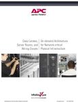
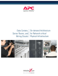
A typical Soyuz three-stage ascent profile and the associated sequence of events are
shown in Figure 2.1. A typical ground track for the lower three stages is presented in the
Figure 2.2 (GTO mission). An example of the evolution of altitude and relative velocity
during the ascent profile of the first three stages is presented in Figure 2.3.
Jettisoning of the payload fairing can take place at different times depending on the aerothermal flux requirements on the payload. Typically, fairing separation takes place
depending on the trajectory between 155 and 200 seconds from liftoff owing to aerothermal flux limitations.
Ascent profile:
1.
2.
3.
4.
5.
6.
7.
Lift-off
First/second stage separation
Fairing jettisoning
Second/third stage separation
Third stage lower skirt jettisoning
Third stage/Fregat separation
Fregat burn for orbit insertion
0s
118
226
288
295
528
588
s
s
s
s
s
s
Figure 2.1 – Typical ascent profile
Arianespace©, January 2006
2-3
Performance and launch mission
Soyuz CSG User’s Manual,
Issue Draft
Figure 2.2 - Typical ground path for the Soyuz three stages (GTO mission)
2-4
Arianespace©, January 2006
Performance and launch mission
Soyuz CSG User’s Manual,
Issue Draft
250000
200000
Altitude (m)
150000
100000
50000
0
0
100
200
300
400
500
600
Time (s)
8000
7000
6000
Velocity (m/s)
5000
4000
3000
2000
1000
0
0
100
200
300
400
500
600
Time (s)
Figure 2.3 – Altitude and relative velocity during the ascent profile of the first three stages
Arianespace©, January 2006
2-5
Performance and launch mission
Soyuz CSG User’s Manual,
Issue Draft
2.3.2. Fregat upper stage flight profile
Following the third stage cut-off, the restartable Fregat upper stage delivers the payload or
payloads to their final orbits. A typical Fregat flight profile is shown in Figure 2.4. This profile
consists of the following events:
•
Intermediate orbit ascent profile: after third stage separation, and Fregat injection
in the parking orbit, Fregat burns are performed to transfer the payload to a wide variety of
final orbits, providing the required plane changes and orbit raising. In this case, the Fregat
ACS thrusters are operated 5 seconds after separation from the third stage followed 55
seconds later with the ignition of the main Fregat engine. Fregat burns are then performed to
transfer the payload as described above.
•
Direct injection profile: a single Fregat burn injects the payload to the final orbit.
Up to 20 burns may be provided by the Fregat to reach the final orbit or to deliver the payload
to the different orbits.
Figure 2.4 – Example of Fregat upper stage mission profile (SSO orbit)
2-6
Arianespace©, January 2006
Soyuz CSG User’s Manual,
Issue Draft
Performance and launch mission
2.3.3. Fregat deorbitation or orbit disposal manoeuvre
After spacecraft separation and following the time delay needed to provide a safe
distance between the Fregat upper stage and the spacecraft, the Fregat typically
conducts a deorbitation or orbit disposal manoeuvre. This manoeuvre is carried out by an
additional burn of the Fregat's ACS thrusters or in some cases by the main engine.
Parameters of the "safe" orbit or entry into the earth's atmosphere will be chosen in
accordance with international laws pertaining to space debris and will be coordinated with
the user during mission analysis.
Arianespace©, January 2006
2-7
Performance and launch mission
Soyuz CSG User’s Manual,
Issue Draft
2.4. General performance data
2.4.1. Geostationary transfer orbit missions
2.4.1.1.
Standard Geostationary Transfer Orbit (GTO)
The geostationary satellites will benefit of the advantageous location of the Guiana Space
Centre: its low latitude minimizes the satellite on-board propellant needed to reach the
equatorial plane, providing additional lifetime.
The Soyuz mission consists in a three stages sub-orbital ascent and two Fregat burns
leading to the injection into the GTO with osculating parameters at separation resulting in
a ΔV requirement on the satellite’s propulsion system of approximately 1500 m/s:
Inclination,
I
= 7 deg.
Alttude of perigee,
Zp
= 250 km
Altitude of apogee,
Za
= 35 786 km
Argument of perigee,
ω
= 178 deg
Notes: Injection is defined as the end of upper stage thrust decay.
Za is equivalent to true altitude at first apogee
The longitude of the first descending node is usually located around TBD deg
West.
The Soyuz performance for this orbit with the RD-0110 or the RD-0124 3rd stage engine
is:
2730 kg and 3060 kg respectively.
n Lift-off
from CSG
Standard GTO mission:
1.
2.
3.
4.
5.
Lift-off
1st Fregat burn – transfer to parking orbit
2nd Fregat burn – transfer to GTO
Satellite separation
Fregat deorbitation
Za = 35 786 km
Zp = 250 km
i = 7 deg.
Figure 2.5 – Standard GTO mission profile
2-8
Arianespace©, January 2006
Performance and launch mission
Soyuz CSG User’s Manual,
Issue Draft
2.4.1.2.
Super and sub Geostationary Transfer Orbits
Refer as well to Chap. 2.4.1.4
The Soyuz mission profile can be adapted to satellites which total mass exceeds or is
lower than the standard GTO LV’s performance. It is applicable to satellites with liquid
propulsion systems giving the possibility of several transfer burns to the GEO and which
tank capacity allows the optimal use of the performance gain.
Satellite mass lower than standard GTO LV performance:
In that case the LV injects the satellite on an orbit with a higher apogee or a lower
inclination requiring a lower velocity increment (∆V) to reach the GEO. The satellite
propellant gain can be used for lifetime extension or for an increase of the satellite drymass.
Satellite mass higher than standard GTO LV performance:
In that case the LV injects the satellite on an orbit with a lower apogee. The satellite
realizes then a Perigee Velocity Augmentation maneuver using proper extra propellant.
The overall propulsion budget of the mission translates in a benefit for the spacecraft in
terms of lifetime (for a given dry-mass) or in terms of dry mass (for a given lifetime)
compared to the standard GTO injection profile.
TO BE ISSUED LATER
Figure 2.6 – Typical Super/Sub GTO performance as function of altitude of apogee.
Arianespace©, January 2006
2-9
Performance and launch mission
Soyuz CSG User’s Manual,
Issue Draft
2.4.1.3. Direct GeoSynchronous equatorial Orbit
Refer as well to Chap. 2.4.1.4
The Soyuz launch vehicle can inject a payload directly into Geo-Synchronous equatorial
Orbit (GSO) by means of a three-burn Fregat mission. The injection scheme is the same
as the one presented for the GTO mission, but with a final Fregat burn to change the
inclination and circularize on the GSO.
The maximum Launch Vehicle performance in GSO is 1340 kg.
2.4.1.4. Super GTO and GSO injection
While the injection orbit for a single launch on Soyuz can be optimized with a higher
apogee, and even, technically speaking, with a launch directly on the GSO, the
standard injection remains on the standard GTO that provides the customer the full
benefit of the compatibility of the two launch systems: Ariane and Soyuz.
2-10
Arianespace©, January 2006
Soyuz CSG User’s Manual,
Issue Draft
2.4.2.
Performance and launch mission
Circular orbits
The typical Soyuz mission includes a three stage sub-orbital ascent and two Fregat burns
as follows:
•
A first burn for transfer to the intermediate elliptical orbit with an altitude of
apogee equal to the target value; and
•
A second Fregat burn for orbit circularization.
2.4.2.1. SSO and Polar orbits
The earth observation, meteorological and scientific satellites will benefit of the Soyuz
capability to delivery them directly into the sun synchronous orbits (SSO) or polar
circular orbits.
The performance on a 660km SSO is 4450 kg (TBC) with the Soyuz 2-1a.
The performance on a 660km SSO is 4900 kg (TBC) with the Soyuz 2-1b.
LV performance data for SSOs are presented in Figure 2.7 as a function of altitude.
Performance data for polar orbits are presented in Figure 2.8.
2.4.2.2. Other circular orbits
Almost all orbit inclinations can be accessed from the CSG.
Supply missions to the International Space Station, satellite constellations deployment
and scientific missions can also be performed by Soyuz from the CSG.
LV performance data for circular orbit missions with inclination 56 and 63 deg, and
altitudes between 400 and 25,000 km are presented in Figure 2.9.
Arianespace©, January 2006
2-11
Performance and launch mission
Soyuz CSG User’s Manual,
Issue Draft
5300
104
5100
103
SSO inclination
102
LV Performance [kg]
101
4700
100
4500
99
4300
98
4100
97
3900
96
3700
3500
300
SSO Inclination [deg.]
LV Performance
4900
95
400
500
600
700
800
900
1000
1100 1200
1300
1400 1500
1600 1700
94
1800
Circular Orbit Altitude [km]
Figure 2.7 – Preliminary LV performance for SSO orbits to be considered for trade-off studies
only. For precise data, please contact Arianespace.
5100
LV Performance [kg]
5000
4900
4800
4700
4600
4500
300
400
500
600
700
800
900
1000
1100
1200
1300
1400
1500
1600
1700
Circular Orbit Altitude [km]
Figure 2.8 – LV performance for polar orbits, to be considered for trade-off studies only. For
precise data, please contact Arianespace
2-12
Arianespace©, January 2006
Soyuz CSG User’s Manual,
Issue Draft
Performance and launch mission
TO BE ISSUED LATER
Figure 2.9 – LV performance for circular orbits. Orbit inclination 56 deg.
Arianespace©, January 2006
2-13
Performance and launch mission
Soyuz CSG User’s Manual,
Issue Draft
2.4.3. Elliptical orbit missions
The Fregat restartable capability offers a great flexibility to servicing a wide range of
elliptical orbits.
A typical Soyuz mission includes the three stages sub-orbital ascent and two or three
Fregat burns, as follows:
•
A first burn to transfer to an initial parking orbit, followed by a coast phase up to
a point corresponding to the required argument of perigee of the targeted
elliptical orbit (in case of sub-orbital mission);
•
A second Fregat burn to transfer to an intermediate elliptical orbit with an altitude
of apogee equal to the target value; and
•
A third Fregat burn to raise the perigee to the required value.
In some cases, when a lower altitude of perigee is required, the mission will be reduced
to two Fregat burns.
LV performance data for a 51.8 degree inclination and a perigee altitude of 200 km are
presented in Figure 2.10 and Figure 2.11.
Specific mission profiles for elliptical orbits can be analyzed on a mission-peculiar basis.
2-14
Arianespace©, January 2006
Performance and launch mission
Soyuz CSG User’s Manual,
Issue Draft
6500
6100
6000
6000
5900
5500
LV Performance [kg]
5800
5000
4500
LV
Pe 4000
rfo
rm 3500
an
ce
[kg 3000
]
5700
5600
5500
5400
5300
5200
5100
5000
400
900
1400
1900
Apogee Altitude [km]
2500
2000
1500
1000
500
0
0
2000
4000
6000
8000
10000
12000
14000
16000
18000
20000
22000
24000
26000
28000
Apogee Altitude [km]
Figure 2.10 - LV performance data for elliptical orbit with 51.8 deg inclination and a perigee
altitude of 200 km. for apogee up to 25 000 km.
TO BE ISSUED LATER
Figure 2.11 - LV performance data for elliptical orbit with 51.8 deg inclination and a perigee
altitude of 200 km. for apogee up to 400 000 km.
Arianespace©, January 2006
2-15
Performance and launch mission
Soyuz CSG User’s Manual,
Issue Draft
2.4.4. Earth escape missions
The performance data for earth escape missions is presented in Figure 2.12 as a function
of the parameter C3 (square of velocity at infinity).
For more accurate data, users should contact Arianespace for a performance estimate
and a mission-adapted profile.
1700
1600
1500
1400
LV Performance [kg]
1300
1200
1100
1000
900
800
*
700
600
500
400
300
0
2
4
6
8
10
12
14
16
18
20
22
24
2
26
2
C 3 [km /s ]
Figure 2.12 –
2-16
28
30
32
34
36
38
40
42
44
46
transition between sub-orbital and direct
* - injection
profile curves is simplified
preliminary LV performance data for escape missions (TBC). For accurate data,
please contact Arianespace
Arianespace©, January 2006
Performance and launch mission
Soyuz CSG User’s Manual,
Issue Draft
2.5. Injection accuracy
The accuracy of the four-stage Soyuz is determined mainly by the performance of the
Fregat upper stage. Conservative accuracy data depending on type of the mission are
presented in Table 2.1. Mission-specific injection accuracy will be calculated as part of the
mission analysis.
Table 2.1 - Injection Accuracy (± 1σ)
Mission –
Circular Orbit
Altitude (km)
GTO
Super/Sub
GTO
Orbital
1000
20,000
35,785 x 250
TBD
3.3
20
23.3
TBD
Altitude of apogee (km)
-
-
40
TBD
Altitude of perigee (km)
-
-
6.6
TBD
6.6 10-4
3.3 10-4
2.6 10-4
TBD
0.033
0.04
0.05
TBD
-
-
0.083
TBD
0.05
0.083
0.083
TBD
Parameters
Semi-major axis (km)
Eccentricity
Inclination (deg)
Argument of perigee
(deg)
RAAN (deg)
Note: Though the accuracy of some injection parameters for Super GTO is less than that
for GTO, the required S/C fuel amount for final orbit correction is approximately the same
in both cases.
2.6. Mission duration
Mission duration from lift-off until separation of the spacecraft on the final orbit depends
on the selected mission profile, specified orbital parameters, injection accuracy, and the
ground station visibility conditions at spacecraft separation.
Typically, critical mission events such as payload separation are carried out within the
visibility of LV ground stations. This allows for the receipt of near-real-time information
on relevant flight events, orbital parameters on-board estimation, and separation
conditions.
The typical durations of various missions (without the visibility constraint of spacecraft
separation) are presented in Table 2.2. Actual mission duration will be determined as
part of the detailed mission analysis, taking into account ground station availability and
visibility.
Arianespace©, January 2006
2-17
Performance and launch mission
Soyuz CSG User’s Manual,
Issue Draft
Table 2.2- Typical Mission Duration (up to Spacecraft Separation) TBD
Mission
GTO and Super/Sub GTO
Circular orbit
Elliptical orbit
Altitude
Mission Duration
(km)
(hh:mm)
20,000 - 120,000
00:20 - 01:30
SSO 800
01:00 - 01:30
10,000
02:00 - 02:30
20,000
03:10 - 03:40
1,000 x 39,464
01:00 - 02:30
Earth escape mission*
Note:
01:15 - 01:45
* - Mission duration depends on declination requirements.
2.7. Launch windows
The Soyuz LV can be launched any day of the year, any time of the day respecting the
specified lift-off time. The inaccuracy of any planned launch time, in a nominal mission
scenario, is less than one second, taking into account all potential dispersions in the
launch sequencing and system start/ignition processes.
The launch window is defined taking in to account the satellite mission requirements such
as the orbit accuracy or the separation orbital position (requirements for the right
ascension of the ascending node [RAAN]) and the respective ability of the launch vehicle
to recover launch time error.
In case of shared (dual) launch, Arianespace will taken into account the launch windows
of each co-passenger to define combined launch window.
In order to allow the possibility of several launch attempts and account for any weather
or technical concern resolution a minimum launch window of 45 minutes is
recommended.
The actual launch window of each mission and its impact on performance will be
calculated as part of mission analysis activities.
2-18
Arianespace©, January 2006
Soyuz CSG User’s Manual,
Issue Draft
Performance and launch mission
2.8. Spacecraft orientation during the flight
During coast phases of the flight the Attitude Control Systems allow the launch vehicle to
satisfy a variety of spacecraft orbital requirements, including thermal control maneuvers,
sun-angle pointing constraints, and telemetry transmission maneuvers. On the contrary,
the active parts of the mission like ascent boost phases and upper stage orbital burns
and TM maneuvers will determine the attitude position of spacecraft. The best strategy to
meet satellite and launch vehicle constraints will be defined with the Customer during the
Mission Analysis process.
2.9. Separation conditions
After injection into orbit, the launch vehicle Attitude Control System is able to orient the
upper composite to any desired attitude(s) and to perform separation(s) in various
modes:
•
3-axis stabilization;
•
longitudinal spin.
After completion of the separation(s) , the launch vehicle carries out a last manœuvre to
avoid subsequent collision.
2.9.1. Orientation performance
The attitude at separation can be specified by the Customer in any direction in terms of :
• Fixed orientation during the entire launch window, or (TBC)
• Time variable orientation dependant on the sun position during the launch window,
For other specific satellite pointing, the Customer should contact Arianespace.
2.9.2. Separation mode and pointing accuracy
The actual pointing accuracy will result from the Mission Analysis.
The following values cover Soyuz compatible spacecrafts as long as their balancing
characteristics are in accordance with para. 4.5.3. They are given as satellite kinematic
conditions at the end of separation and assume the adapter and separation system are
supplied by Arianespace.
In case the adapter is provided by the Satellite Authority, the Customer should contact
Arianespace for launcher kinematic conditions just before separation.
Possible perturbations induced by spacecraft sloshing masses are not considered in the
following values.
2.9.2.1.
Three-Axis stabilized mode
The 3-σ attitude accuracy for a three-axis stabilized mode are:
2.9.2.2.
•
geometrical axis depointing ≤ 1 deg
•
angular tip-off rates along longitudinal axis ≤ 0.3 deg/s
•
angular tip-off rates along transversal axis ≤ 0.3 deg/s
Spin stabilized mode
The Fregat ACS can provide a roll rate around the upper composite longitudinal axis
between TBD deg/s and 30 deg/s, clockwise or counterclockwise. Higher spin rates are
possible but shall be specifically analyzed.
Arianespace©, January 2006
2-19
Performance and launch mission
Soyuz CSG User’s Manual,
Issue Draft
Although the spacecraft kinematic conditions just after separation are highly dependant
on the actual spacecraft mass properties (including uncertainties), and the spin rate, the
following values are typical results.
The 3-σ attitude accuracy for a 30 deg/sec spin mode are:
•
Spin rate accuracy ≤ 1 deg/s
•
Transverse angular tip-off rates ≤ 0.3 deg/s
•
Depointing of kinetic momentum vector, half angle ≤ 1 deg
•
Nutation, angle ≤ 10 deg.
1.Orientation of composite around Z axis
2.Orientation of composite around Y axis
3.Spin-up
4.Spacecraft separation
5.Spin down
6.Orientation for deorbitation
Figure 2.13 – Typical separation sequence.
2.9.2.3.
Separation linear velocities and collision risk avoidance
The payload adapter’s separation systems are designed to deliver a minimum relative
velocity between spacecraft and upper stage ranging from 0.3 m/s to 1m/s.
For each mission, Arianespace will verify that the distances between orbiting bodies are
adequate to avoid any risk of collision until the launcher final maneuver.
For this analysis, the Customer has to provide Arianespace with its orbit and attitude
maneuver flight plan, otherwise the spacecraft is assumed to have a pure ballistic
trajectory (i.e. no s/c maneuver occurs after separation).
After completion of the separation(s), the launch vehicle carries out a dedicated
maneuver to avoid the subsequent collision or the satellite orbit contamination.
2-20
Arianespace©, January 2006
Soyuz CSG User’s Manual,
Issue Draft
2.9.2.4.
Performance and launch mission
Multi-separation capabilities
The Soyuz LV is also able to perform multiple separations with mission peculiar payload
dispensers or the internal dual launch carrying structure. A conceptual definition of this
kind of dispenser is presented in Annex TBD, the dual launch carrying structure is defined
in chapter 5. In this case the kinematics conditions presented above will be defined
through the dedicated separation analysis.
For more information, please contact Arianespace.
Arianespace©, January 2006
2-21
Introduction
Soyuz CSG User’s Manual,
Issue Draft
1.2. European Space Transportation System
To meet all Customer’s requirements and to provide the highest quality of services,
Arianespace proposes to Customer a fleet of launch vehicles: Ariane, Soyuz and Vega.
Thanks to their complementarities, they cover all commercial and governmental mission
requirements, providing access to the different type of orbits from Low Earth Orbit to
Geostationary Transfer Orbit and even to interplanetary one. This family approach
provides Customers with a real flexibility to launch their spacecrafts and insure in a
timely manner their planning for orbit delivery.
The Soyuz operation complements the Ariane 5 and Vega offer in the medium-weight
payload class for low earth orbit, and provides additional flexibility in delivery of satellite
up to 3 t to GTO orbit.
The decision to operate Soyuz from the Guyana Space Centre (CSG) was taken by the
European Space Agency May 27, 2003 associated with a perspective of evolution of the
European launcher sector for the 2010 timeframe. These decisions covered the continuity
of the Ariane 5 launch service, the development and commercial availability of the Vega
small launch vehicle from 2008 onwards, and the Soyuz commercial operations from the
Guiana Space Centre, starting in 2008.
The exclusive exploitation of this launch vehicle family was entrusted to Arianespace – a
unique launch services operator relying on the European and Russian space industry.
The Customer will appreciate the advantages and possibilities brought by the present
synergy, using a unique high quality rated launch site, a common approach to the
LV/spacecraft suitability and launch preparation, and the same quality standards for
mission integration and management.
1-2
Arianespace©, January 2006
Introduction
Soyuz CSG User’s Manual,
Issue Draft
1.3. Arianespace launch services
Arianespace offers to its customers reliable and proven launch services that include:
•
Exclusive
marketing,
sales
and
management of Ariane-5, Soyuz, and
Vega operations;
•
Mission management and support
that covers all aspects of launch
activities
and
preparation
from
contract signature through launch;
•
Systems engineering
analysis;
•
Procurement,
verification,
and
delivery of the launch vehicle and all
associated hardware and equipment,
including all adaptations required to
meet customer requirements;
•
Ground facilities and support (GRS)
for customer activities at launch site;
•
Combined operations at launch site,
including
launch
vehicle
and
spacecraft integration and launch;
•
Launcher telemetry and tracking
ground station support and postlaunch activities;
•
Assistance and logistics support,
which may include transportation and
assistance with insurance, customs,
and export licenses;
•
Quality
and
activities;
•
Insurance and financing services on a
case by case basis.
safety
support
and
assurance
Arianespace provides the customer with a project oriented management system, based
on a single point of contact (the Program Director) for all launch service activities, in
order to simplify and streamline the process, adequate configuration control for the
interface documents and hardware, transparence of the launch system to assess the
mission progress and schedule control.
Arianespace©, January 2006
1-3
Introduction
Soyuz CSG User’s Manual,
Issue Draft
1.4. Soyuz launch vehicle family
1.4.1. History
The Soyuz is the most recent of a long line of Soyuz family vehicles that, taken together,
are acknowledged to be the most frequently rockets launched in the world. Vehicles of
this family, that launched both the first satellite (Sputnik, 1957) and the first man (Yuri
Gagarin, 1961) into space, have been credited with more than 1700 launches to date.
The three-stage version known as Soyuz, first introduced in 1966, has been launched
more than 850 times. Due to their close technical similarity (same lower three stages),
the Molniya and Soyuz vehicles are commonly combined together for reliability
calculations. In the last 25 years they have completed a success rate of 98,1% over
more than 950 launches. As the primary manned launch vehicle in Russia and the former
Soviet Union, and as today one of the primary transport to the International Space
Station, the Soyuz has benefited from these standards in both reliability and robustness.
The addition of the flexible, restartable Fregat upper stage in 2000 allows the Soyuz
launch vehicle to perform a full range of missions (LEO, SSO, MEO, GTO, GEO, and
escape).
Table 1.1 shows a timeline of LV Soyuz development.
Table 1.1 - Soyuz LV Family Evolution
1957 – 1960
R-7A / Sputnik (Two-stage missile used to launch the Sputnik payload
- no longer in production)
1958 – 1991
Vostok (Three-stage LV with the block E as third stage - no longer in
production)
1960 –
Molniya* (Four-stage LV with the block I as third stage and block L or
ML as upper stage)
1963 – 1976
Voskhod (Three-stage LV with the block I as third stage - no longer in
production)
1966 – 1976
Soyuz (Voskhod upgrade for the launch of the Soyuz manned capsule no longer in production)
1973 –
Soyuz U (Unified LV for the replacement of Voskhod, Soyuz )
1982 – 1995
Soyuz U2 (Soyuz-U upgrade for use of the improved fuel “Sintin” in the
second stage - no longer in production)
1999
Introduction of Ikar upper stage for commercial missions (no longer in
production)
2000
Introduction of Fregat upper stage
2001
Introduction of upgraded first and second stage engines, RD-107A and
RD-108A
2004/6
Introduction of a digital control system, the ST fairing and the
upgraded third stage engine, RD-0124
Note:
* Molniya launch vehicle is still operational and will be progressively replaced by
the Soyuz with the Fregat upper stage.
1-4
Arianespace©, January 2006
Introduction
Soyuz CSG User’s Manual,
Issue Draft
The Soyuz is launched from the Baikonur Cosmodrome in Kazakhstan, from the Plesetsk
Cosmodrome in the North of Russia and from the Guiana Space Centre in French Guiana
to meet the needs of the commercial market and continuing to serve the needs of
Russian government and other institutional and international programs.
Soyuz LVs continue to be mass-produced in Samara, Russia, by the Samara Space
Center, whose facilities have been designed to accommodate the production of up to four
LVs per month. As a result of the continued demand from the Russian government,
International Space Station activity, and commercial orders, the Soyuz LV is in
uninterrupted production at an average rate of 10 to 15 LVs per year with a capability to
rapidly scale up to accommodate users’ needs.
The Fregat upper stage production by NPO Lavochkine, Moscow, Russia is well suited
with this production rate.
1.4.2. Vehicle Reliability
Table 1.2 shows the information on Soyuz reliability. Reliability figures are presented
individually for the lower three stages of the vehicle and for the Fregat upper stage. This
is primarily due to the large statistical database of flights with the lower three stages. To
provide most relevant data to future missions, it was chosen to present reliability figures
for the flights performed in the past 25 years. The figures presented include the “Soyuz”
and “Molniya” flights, as these two configurations has a nearly identical lower three
stages. Furthermore, since 1977, the “Soyuz” and “Molniya” configurations are the only
vehicles of the Soyuz family to remain in production, replacing all previous versions.
Table 1.2 - Flight Success Ratio
Component/Vehicle
Soyuz & Molniya
Fregat upper stage
Time frame
1977 - 2005
2000 - 2005
Number of Flights
968
8
Number of Failures
19
0
Flight Success Rate (%)
98
100
Note:
The flight success rate is the overall ratio of successful flights over flight
attempts. It takes into account all launch system failures, regardless of
corrections or modifications.
Taken into account the design objectives and extensive qualification program, it
is projected that the flight reliability of Soyuz with the new components of the
launch vehicle such as the larger payload fairing, third stage engines and control
system will not be affected.
Arianespace©, January 2006
1-5
Introduction
Soyuz CSG User’s Manual,
Issue Draft
1.5. Launch system description
Arianespace offers a complete launch system including the vehicle, the launch facilities,
and the associated services.
1.5.1. Launch vehicle general data
The Soyuz LV consists primarily of the following components:
•
A lower composite consisting of four liquid-fueled boosters (first stage), a core
(second) stage, and a third stage;
•
A restartable Fregat upper stage;
•
A payload fairing and interstage section; and
•
A payload adapter/dispenser with separation system(s). Depending on the mission
requirements, a variety of different adapters/dispensers may be used.
The Soyuz configuration used at CSG and corresponded vehicle data is shown in Figure
1.1 and outlined in the Annex 5.
1-6
Arianespace©, January 2006
Introduction
Soyuz CSG User’s Manual,
Issue Draft
PAYLOAD FAIRINGS
Fairing
Diameter:
Length:
Mass:
Structure:
Separation
Interstage
Mass:
Structure:
FREGAT UPPER STAGE
ST
4.110 m
11.433 m
1700 kg
Two-half-shell carbonfiber reinforced plastic
Mechanical
locks/
pneumatic jack/pushers
S
3.715 m
7.700 m
1045 kg
Two-half-shell aluminum
skin-stringer
Mechanical
locks/Spring
jack/pushers
400 kg
aluminum skin-stringer
350 kg
Aluminum-skin stringer
Size:
Inert mass:
Propellant:
Subsystems:
Structure:
3.35-m diameter × 1.50-m height
950 kg
5350-kg N2O4/UDMH
Propulsion
- Thrust
- Isp
- Feed system
- Pressurization
- Burn time / Restart
Attitude Control
- pitch, yaw
PAYLOAD ADAPTERS
Off-the-shelf devices:
1194SF
937SF
1666SF
.
.
Size:
Gross/Dry mass:
Propellant:
Subsystems:
Structure
- roll
Avionics
(110 kg);
(45 kg);
(100 kg)
Stage separation:
1st STAGE
(FOUR BOOSTERS)
2.68-m diameter ×
length
44 413 kg / 3 784 kg
27 900-kg LOX
11 260-kg Kerosene
2nd STAGE (CORE)
19.60-m
.
2.95-m diameter × 27.10-m
length
99 765 kg / 6 545 kg
63 800-kg LOX
26 300-kg Kerosene
Pressure stabilized aluminium
alloy tanks with intertanks skin
structure
RD-107A 4-chambers engine,
Pressure stabilized aluminum
alloy tanks with intertanks
skin structure
RD-108A 4-chambers engine,
- Thrust
- Isp
- Feed system
838.5 kN – SL; 1021.3 kN –Vac
262 s – SL; 319 s –Vac
pump-fed by hydrogen peroxide
(H2O2) gas generator
792.5 kN – SL; 990.2 kN –Vac
255 s – SL; 319 s –Vac
pump-fed
by
hydrogen
peroxide (H2O2) gas generator
- Pressurization
Liquid nitrogen (N2)vaporization
Liquid
nitrogen
vaporization
- Burn time / Restart
118 s / No – two level thrust
throttling
Two 35-kN vernier thrusters and
one aerofin
Input/Output units, TM, power
286 s / No – one level thrust
throttling
Four 35-kN vernier thrusters
Pyronuts/pushers/reaction
nozzle
Pyronuts and 3rd stage engine
ignition
Propulsion
Attitude Control
Avionics
Stage separation:
Input/Output units, TM, power
Figure 1.1 – LV property data
Arianespace©, January 2006
(N2)
1-7
Structurally
stable
aluminum
alloy
6
spherical tanks/8 cross rods
S5.92
Two mode thrust 19.85/14.00 kN - Vac
Two mode thrust 331/316 s - Vac
Pump-fed, open cycle gas generator
Ghe vaporization
Up to 900 s / up to 20 controled or depletion
burn
Main engine translation or eight 50-N
hydrazine thrusters
Four 50-N hydrazine thrusters
Inertial 3-axis platform, on-board computer,
TM & RF systems, Power
gas pressure locks/pushers
3rd STAGE
.
2.66-m diameter × 6.70-m length
27 755 kg / 2 355 kg
17 800-kg LOX
7 600 kg Kerosene
Pressure stabilized aluminum alloy tanks with
intertanks and rear skin structure
RD-0110
4-chamber
engine (Soyuz 2-1a)
297.9 kN (Vac)
325 s -Vac
Pump-fed gas
generator, generator’s
gas blow down through
verniers
Oxygen
vaporization/generator
gases
250 s / No
RD-0124 4-chamber
engine (Soyuz 2-1b)
297.9 kN (Vac)
359 s (Vac)
Multi-stage pump-fed
close
cycle
gas
generator
Helium vaporization
270 s / No
Four
6-kN
vernier
Each
chambers
thrusters
gimbaling in one axis
Centralized control system: inertial 3-axis
platform, on-board computer, TM & RF system,
power
Introduction
Soyuz CSG User’s Manual,
Issue Draft
1.5.2. European spaceport and CSG Facilities
The launch preparation and launch are carried out from the Guiana Space Centre (CSG) –
European spaceport operational since 1968 in French Guiana. The spaceport
accommodates Soyuz, Ariane-5 and Vega separated launch facilities (ELS, ELA and ELV
respectively) with common Payload Preparation Complex EPCU and launch support
services.
The CSG is governed under an agreement between France and the European Space
Agency that was recently extended to cover Soyuz and Vega installations. The day to day
life of CSG is managed by French National Agency (Centre National d’Etude Spatiales –
CNES) on behalf of the European Space Agency. CNES provides all needed range
support, requested by Arianespace, for satellite and launch vehicle preparation and
launch.
The CSG provides state-of–the-art Payload Preparation Facilities (Ensemble de
Preparation Charge Utile – EPCU) recognized as a high quality standard in space industry.
The facilities are capable to process several satellites of different customers in the same
time, thanks to large cleanrooms and supporting infrastructures. Designed for Ariane-5
dual launch capability and high launch rate, the EPCU capacity is sufficient to be shared
by the Customers of all three launch vehicles.
The satellite/launch vehicle integration and launch are carried out from launch sites
dedicated for Ariane, Soyuz or Vega.
The Soyuz Launch Site (Ensemble de Lancement Soyuz – ELS) is located some 10 km
North of the existing Ariane 5 launch facilities and provides the same quality of services
for payload.
The moderate climate, the regular air and sea connection, accessible local transportation,
and excellent accommodation facilities as for business and for recreation– all that
devoted to User’s team and invest to the success of the launch mission.
1-8
Arianespace©, January2006
Introduction
Soyuz CSG User’s Manual,
Issue Draft
Soyuz launch area
Ariane launch area
Vega launch area
Figure 1.2 – CSG overview
Arianespace©, January 2006
1-9
Introduction
Soyuz CSG User’s Manual,
Issue Draft
1.5.3. Launch service organization
Arianespace is organized to offer a Launch Service based on a continuous interchange of
information between a Spacecraft Interface Manager (Customer), and the Arianespace
Program Director (Arianespace) who are appointed at the time of the launch contract
signature. As from that date, the Ariane Program Director is responsible for the execution
of the Launch Service Contract. For a given launch, therefore, there can be one or two
Spacecraft Interface Manager(s) and one or two Arianespace Program Directors,
depending on whether the launch is a single or dual one with different customers.
For the preparation and execution of the Guiana operations, the Arianespace launch team
is managed by a specially assigned Mission Director who will work directly with the
Customer’s operational team.
Customers Authorities
Ariane Authority
Arianespace
Launch Vehicle
Manufacturing
Spacecraft 1
Interface
Manager
Arianespace
Program
Director 1
Arianespace
Launch
Operations
Program
Director 2
Spacecraft 2
Interface
Manager
Operations
1.
Safety
submiss
C
S
G
Principle of Customers/Arianespace relationship (dual launch)
1-10
Arianespace©, January2006
Soyuz CSG User’s Manual,
Issue Draft
Introduction
1.6. Corporate organization
1.6.1. Arianespace
Arianespace is a French joint stock company (“Societe Anonyme”) which was
incorporated on March 26th 1980 as the first commercial space transportation company.
In order to meet the market needs, Arianespace has established a worldwide presence:
in Europe, with headquarter located at Evry near Paris, France; in North America with
Arianespace Inc., its subsidiary in Washington D.C., and in the Pacific Region, with its
representative offices in Tokyo (Japan) and Singapore.
Arianespace is the international leader in commercial launch services, and today holds an
important part of the world market for satellites launched to the geostationary transfer
orbit (GTO). From its creation in 1980, Arianespace has successfully performed over 160
launches and signed contracts for more than 250 payloads with some 55
operators/customers.
Arianespace provides each customer a true end-to-end service, from manufacture of the
launch vehicle to mission preparations at the Guiana Space Centre and successful in-orbit
delivery of payloads for a broad range of mission.
Arianespace as a unique commercial operator oversees the marketing and sales,
production and operation from CSG of Ariane, Soyuz and Vega launch vehicles.
Arianespace continues the Soyuz commercial operations started in 1999 in Baikonur by
Starsem having as of January 2006 a record of 15 successful launches.
Figure 1.3 – The Arianespace worldwide presence
Arianespace©, January 2006
1-11
Introduction
Soyuz CSG User’s Manual,
Issue Draft
1.6.2. Partners
Arianespace is backed by shareholders that represent the best technical, financial, and
political resources of the 12 European countries participating in the Ariane and Vega
programs:
•
22 Aerospace engineering companies from 10 European countries
•
1 Space agency
Building on the experience gained by its daughter company Starsem since 1996 with the
Soyuz launches from Baikonur, the Soyuz operation from CSG results of a transfer of the
Soyuz commercial concession to Arianespace, that will allow to improve the services
provided on the commercial market.
Starsem is a 50/50 joint venture between Russian and European partners that draws on
some of the worldwide best–known names in the space industry:
•
The European Aeronautic
Company – EADS
Defense
•
Arianespace
•
The Russian Federal Space Agency
•
The Samara Space Center TsSKB-Progress
and
Space
Starsem board consisting of representative of the three leading companies and space
agency still covers the strategic decisions and common policy with regard to the
commercial operation of Soyuz providing production and institutional support.
1-12
Arianespace©, January2006
Introduction
Soyuz CSG User’s Manual,
Issue Draft
1.6.3. European Space transportation system organization
Arianespace benefits from a simplified procurement organization that relies on a prime
supplier for each launch vehicle. The prime supplier backed by his industrial organization
is in charge of production, integration, and launch preparation of the launch vehicle.
The prime suppliers for Ariane and Vega launch vehicle are respectively EADS LV and
European Launch Vehicle (ELV). The prime supplier for the Soyuz launch vehicle is the
Russian Federal Space Agency with SSC TsSKB-Progress as the Soyuz LV Authority, and
NPO Lavotchkine as the provider of the Fregat upper stage.
Ariane, Soyuz and Vega launch operations are managed by Arianespace with the
participation of the prime suppliers and range support from CNES CSG.
The Soyuz operational team is based on SSC TsSKB-Progress, NPO L and KB OM representatives
who are responsible for Soyuz LV preparation.
Figure 1.4 shows the launch vehicle procurement organization.
To illustrate the industrial experience concentrated behind the Soyuz prime supplier, the
Figure 1.5 shows second level subcontractors and their responsibilities.
CUSTOMER
Qualification
Authority
Qualification
Authority
ESA
ARIANESPACE
VEGA
ARIANE
Federal Space Agency
STARSEM
SOYUZ
EADS LV
ELV
Federal Space Agency
TsSKB-Progress
Range Support:
NPO L
and
Figure 1.4 – The launch vehicle procurement organization
Arianespace©, January 2006
1-13
Introduction
Soyuz CSG User’s Manual,
Issue Draft
1.6.4. Main suppliers
1.6.4.1. Russian Federal Space Agency
The Agency (FSA) represents the Russian federal executive authority
that defines the Russian Federation's national policy in the field of space
research and exploration. The agency also performs interdisciplinary
coordination of national scientific and application space programs. It was
created in February 1992 by a decree issued by the President of the
Russian Federation.
FSA's responsibilities include: development and implementation of Russian national space
policy; acting as governmental customer in the development of scientific and application
space systems, facilities and equipment; establishing international cooperation and
collaboration in space research, and organization/coordination of commercial space
programs.
Operations under FSA responsibility include more than 400 aeronautic and space
companies and organizations.
1.6.4.2. The Samara Space Centre “TsSKB-Progress”
The Samara Space Center "TsSKB-Progress" was created in 1996 by
combining the TsSKB Central Samara Design Bureau and the "Progress"
production plant.
The Samara Space Center is one of the world leaders in the design of
launchers, spacecraft and related systems. Its history goes back to the
start of the space program in 1959 when a branch of the Moscow OKB-1
design bureau was established in the city of Kuibyshev (now known as
Samara).
The Center developed a family of launch vehicles derived from the OKB-1's R-7
intercontinental ballistic missile. Approximately 10 versions were developed, including
Sputnik (which carried the first man-made satellite into orbit), Vostok (used for the initial
manned space flight), Molniya, and Soyuz.
In addition to years of experience building launch vehicles, TsSKB-Progress has also built
numerous earth observation and scientific satellites.
1.6.4.3. NPO Lavotchkine
NPO Lavotchkine was founded in 1937 as an aircraft manufacturer and, is
one of the industry leaders in the development and implementation of
interplanetary, astrophysical and earth monitoring projects such as :
- National programs: Luna, Mars, Venera, Bankir
- International programs: VEGA, Phobos, IRS-1, Granat, Mars-96, Interbol,
Klaster
- Advanced programs : Spektr, Phobos-Grunt, Solnyechniy Zond, and others.
NPO Lavotchkine adapts, produces and is the technical authority for the Fregat upper
stage. NPO Lavotchkin is also the technical authority for the assembled upper composite.
1.6.4.4 KB OM
V.P. Barmin Design Bureau for General Engineering, was founded in 1941. KBOM
specialises in the design and operation of launch facilities, space rocket ground
infrastructure and in orbit processing equipment.
KB-OM is in charge of the development of the Russian systems for the Soyuz launch zone
at the CSG.
1-14
Arianespace©, January2006
Introduction
Soyuz CSG User’s Manual,
Issue Draft
SSC "TsSKB-Progress", Samara, Russia
Fairing ST
NPO Lavochkin, Khimki, Russia
Fairing S
EADS, Europe
Payload Adapter /
Dispenser
NPOLavochkin.
Lavotchkine
NPO
Khimki, Russia
FREGAT Upper Stage
NPO
Lavotchkine,
Khimki,
Russia
NPO
Lavochkin,
Khimki,
Russia
Entire stage
(structure, power, thermal & RF system,
NPO
Lavotchkine
NPO
Lavochkin.
Khimki, Russia
Interstage structure
NPTs AP, Moscow, Russia
Control system
RNII KP & OKB MEI
Moscow, Russia
Tracking systems
OKB Orion
Moscow, Russia
Batteries
NPO Avtomatika
Ekaterinburg, Russia
Digital control system
for all stages
Izevsky radiozavod
Izevsk, Russia
TM system
KB Khimash
Moscow, Russia
Attitude Control thrusters
KB Khimash
Moscow, Russia
S5.92 engine
RNII KP
Moscow, Russia
Telemetry System
SSC "TsSKB-Progress"
Samara, Russia
rd
3 stage (tanks, stage integration, tests)
Voronyezh Mechanical Factory
Voronyezh, Russia
rd
3 stage engine (RD-0110 or RD-0124)
SSC "TsSKB-Progress"
Samara, Russia
nd
2 (core) stage (tanks, stage integration, tests)
SSC "TsSKB-Progress"
Samara, Russia
st
1 stage boosters (tanks, stage integration, tests)
AO Motorostroitel
Samara, Russia
2nd stage engine (RD-108A)
AO Motorostroitel
Samara, Russia
st
1 stage engines (RD-107A)
KB OM
Moscow, Russia
Moscow,
Russia
Launch
Pad
and launch pad operations
French Guiana, France
Launch pad and launch pad operations
Figure 1.5 – The Soyuz subcontractors
Arianespace©, January 2006
1-15
Soyuz CSG User’s Manual,
Issue Draft
ENVIRONMENTAL CONDITIONS
Chapter 3
3. - Environmental conditions
3.1. General
During the preparation for launch at the CSG and then during the flight, the spacecraft is
exposed to a variety of mechanical, thermal, and electromagnetic environments. This
chapter provides a description of the environment that the spacecraft is intended to
withstand.
All environmental data given in the following paragraphs should be considered as limit
loads, applying to the spacecraft. The related probability of these figures not being
exceeded is 99 %.
Without special notice all environmental data are defined at the spacecraft base, i.e. at
the adapter/spacecraft interface.
The following sections present the environment for the two configurations Soyuz 2-1a
and Soyuz 2-1b. It is further noted that the introduction of the RD-0124 engine on the
Soyuz 2-1b configuration is not expected to measurably affect either the quasi-static
loads or the sine-vibration levels since its thrust is identical to that of the RD-0110
engine, and moreover, a sequenced shut-down profile is implemented to reduce the
transient loads at the end of the third stage flight.
Arianespace©, January 2006
3-1
Environmental conditions
Soyuz CSG User’s Manual,
Issue Draft
3.2. Mechanical environment
3.2.1. Steady state acceleration
3.2.1.1. On ground
The flight steady state accelerations described hereafter cover the load to which the
spacecraft is exposed during ground preparation.
3.2.1.2. In flight
During flight, the spacecraft is subjected to static and dynamic loads. Such excitations may
be of aerodynamic origin (e.g., wind, gusts, or buffeting at transonic velocity) or due to the
propulsion systems (e.g., longitudinal acceleration, thrust buildup or tail-off transients, or
structure-propulsion coupling, etc.).
Figure 3.1 shows a typical longitudinal static acceleration-time history for the LV during its
ascent flight. The highest longitudinal acceleration occurs just before the first-stage cutoff
and does not exceed 4.3 g.
The highest lateral static acceleration may be up to 0.4 g at maximum dynamic pressure
and takes into account the effect of wind and gust encountered in this phase.
The accelerations produced during Fregat flight are negligible and enveloped by the
precedent events.
Figure 3.1 – Typical Longitudinal Steady-state Static Acceleration (first three stages flight)
3-2
Arianespace©, January 2006
Environmental conditions
Soyuz CSG User’s Manual,
Issue Draft
3.2.2. Sine-equivalent dynamics
Sinusoidal excitations affect the LV during its powered flight (mainly the atmospheric flight),
as well as during some of the transient phases.
The envelope of the sinusoidal (or sine-equivalent) vibration levels at the spacecraft base
does not exceed the values given in Table 3.1.
The sinusoidal excitation above 40 Hz is insignificant.
Table 3.1 - Sine Excitation at Spacecraft Base
Direction
Longitudinal
Frequency Band (Hz)
Sine Amplitude (g)
Lateral
5 – 10
10 – 30
30 – 40
1–5
5 – 30
30 – 40
0.5
1.0
0.6
0.3
0.8
0.6
3.2.3. Random vibration
Random vibrations at the spacecraft base are generated by propulsion system operation and
by the adjacent structure’s vibro-acoustic response. Maximum excitation levels are obtained
during the first-stage flight. Acceleration power spectral density (PSD) and root mean
square vibration levels (GRMS) are given in Table 3.2 along each of three axes. The random
vibrations must be taken into account for equipment dimensioning in the 40 – 100 Hz
frequency range, considering that at higher frequency it is covered by acoustic loads.
Event
Table 3.2 – The maximum flight levels of random vibrations at Spacecraft Base
Frequency Band (Hz)
Duration of
GRMS
20 – 50 50-100 100-200 200-500
5001000application
(g)
1000
2000
(s)
PSD, Power Spectral Density(1) (g²/Hz)
1st stage flight
2nd stage and
3rd stage flight
0.0050
0.0050
0.0100
0.0100
0.0250
0.0250
0.0250
0.0100
0.0100
0.0050
4.94
120
0.0025
0.0025
0.0050
0.0050
0.0100
0.0100
0.0100
0.0050
0.0050
0.0025
3.31
480
0,0020
0,0010
1,63
875
0,0010
Note: (1) - Changes of the Power Spectral Density in frequency sub-ranges is linear, when a
logarithmic scale is used for both frequency and Power Spectral Density.
FREGAT flight
0,0020
Arianespace©, January 2006
0,0020
0,0020
0,0020
3-3
Environmental conditions
Soyuz CSG User’s Manual,
Issue Draft
3.2.4. Acoustic vibration
3.2.4.1. On Ground
The noise level generated by the venting system does not exceed 94 dB.
3.2.4.2. In Flight
Acoustic pressure fluctuations under the fairing are generated by engine operation (plume
impingement on the pad during liftoff) and by unsteady aerodynamic phenomena during
atmospheric flight (i.e., shock waves and turbulence inside the boundary layer), which are
transmitted through the upper composite structures. Apart from liftoff and transonic flight,
acoustic levels are substantially lower than the values indicated hereafter.
The envelope spectrum of the noise induced inside the fairing during flight is shown in Table
3.3. It corresponds to a space-averaged level within the volume allocated to the spacecraft
stack, as defined in Chapter 5. The acoustic spectrum defined below covers excitations
produced by random vibration at the spacecraft base for frequency band above 100 Hz.
It is assessed that the sound field under the fairing is diffuse.
Table 3.3 - Acoustic Noise Spectrum under the Fairing
Flight Limit Level (dB)
Octave Center
(reference: 0 dB = 2 x 10⁻⁵ Pa)
Frequency (Hz)
ST-Type Fairing
31.5
125
63
132
125
134
250
136
500
134
1000
125
2000
121
OASPL (20 – 2828 Hz)
141
Note: OASPL – Overall Acoustic Sound Pressure Level
This maximum environment is applied during a period of approximately 60 seconds: 15
seconds for lift-off and 45 seconds for atmospheric flight.
3-4
Arianespace©, January 2006
Soyuz CSG User’s Manual,
Issue Draft
Environmental conditions
3.2.5. Shocks
The spacecraft is subject to shock primarily during stage separations, fairing jettisoning,
and actual spacecraft separation.
The envelope acceleration shock response spectrum (SRS) at the spacecraft base
(computed with a Q-factor of 10) is presented in Table 3.4, Table 3.5 and Figure 3.12.
These levels are applied simultaneously in axial and radial directions.
For customers wishing to use their own adapter the acceptable envelope at the launch
vehicle interface will be provided on a peculiar base.
Arianespace©, January 2006
3-5
Environmental conditions
Soyuz CSG User’s Manual,
Issue Draft
Table 3.4 - Shock Response Spectra at Stage Separations and Fairing Jettisoning
Frequency (Hz)
100 – 1000
Flight Event
1000 – 5000
SRS, Shock Response Spectra
(Q = 10) (g)
Fairing separation, upper-stage separation
15 – 350
350
Table 3.5 - Shock Response Spectra for off-the-shelf Clampband Separation Systems
Frequency (Hz)
Spacecraft
Adapter
Interface
Diameter
Band
Tension
kN
100
Ø 937
≤ 18.3
20
Ø 937
(type B)
≤ 27.7
20
Ø 1194
≤ 28.2
20
1700
Ø 1666
≤ 32
20
1800
600
800
1500
2000
5550
8000
10000
SRS, Shock Response Spectra (Q = 10) (g)
2000
3500
2000
2000
2000
2000
3200
4147
4550
4550
5000
5000
5000
5000
3500
3500
3500
3500
TO BE ISSUED LATER
Figure 3.2 - Envelope acceleration shock response spectrum (SRS) at the spacecraft base
3-6
Arianespace©, January 2006
Environmental conditions
Soyuz CSG User’s Manual,
Issue Draft
3.2.6. Static pressure under the fairing
3.2.6.1. On Ground
After encapsulation, the air velocity around the spacecraft due to the ventilation system is
lower than 5 m/sec (value experienced in front of the air inlet). The velocity may locally
exceed this value; contact Arianespace for specific concern.
3.2.6.2. In Flight
The payload compartment is vented during the ascent phase through one-way vent doors
insuring a low depressurization rate of the fairing compartment.
The static pressure evolution under the fairing is shown in Figure 3.3. The depressurization
rate does not exceed 2,0 kPa/s (20 mbar/s) for a sustained length of time. Locally at the
time of maximum dynamic pressure, at ~ 50s, there is a short period of about 2 seconds
when the depressurization rate can reach 3,5 kPa/s (35 mbar/s)).
The difference between the pressure under fairing and free-stream external static
pressures, at the moment of the fairing jettisoning, is lower than 0,2 kPa (2 mbar).
Pressure variation under fairing
120
Pmax
Pmin
100
Pressure [kPa]
80
60
40
20
0
0
10
20
30
40
50
60
70
80
90
100
Time [s]
Figure 3.3 - Typical pressure variation under the fairing
Arianespace©, January 2006
3-7
Environmental conditions
Soyuz CSG User’s Manual,
Issue Draft
0
d(Pc)/dt (mbar/s)
-5
-10
-15
-20
0
10
20
30
40
50
60
70
80
90
100 110 120
Time (s)
Figure 3.4 – Typical depressurization rate under fairing
3-8
Arianespace©, January 2006
Soyuz CSG User’s Manual,
Issue Draft
Environmental conditions
3.3. Thermal environment
3.3.1. Introduction
The thermal environment provided during spacecraft preparation and launch has to be
considered at following phases:
•
•
Ground operations:
o
The spacecraft preparation within the CSG facilities;
o
The upper composite and launch
encapsulated inside the fairing
vehicle
operations
with
spacecraft
Flight
o
Before fairing jettisoning;
o
After fairing jettisoning
3.3.2. Ground operations
The environment that the spacecraft experiences both during its preparation and once it is
encapsulated under the fairing is controlled in terms of temperature, relative humidity,
cleanliness, and contamination.
3.3.2.1. CSG Facility Environments
The typical thermal environment within the most of air-conditioned CSG facilities is kept
around 23°C ± 2°C for temperature and 55% ± 5% for relative humidity.
More detailed values for each specific hall and buildings are presented in the EPCU User’s
Manual and in Chapter 6.
3.3.2.2. Thermal conditions under the fairing
During the encapsulation phase and once mated on the launch vehicle, the spacecraft is
protected by an air-conditioning system provided by the ventilation through the pneumatic
umbilicals: high flow rate (H), and through the launch vehicle for the last 45 minutes, when
the
gantry
has
been
rolled
away:
low
flow
rate
(L).See
fig
3.5.
Arianespace©, January 2006
3-9
Environmental conditions
Soyuz CSG User’s Manual,
Issue Draft
Table 3.6 - Air Conditioning under the Fairing
Phase
Airconditioning
system
Temperature
Relative
Humidity
Flow, Nm3/h
Duration
"ICE" system
if necessary
2 weeks max
Operations
in UCIF
UCIF
airconditioning
system
23 ± 1°C
Transfer
from UCIF
to Launch
Pad
CARAVAN
16°C
< 60%
1500
~3 h
< 27°C
< 60%
No venting,
overpressure
.
1h
Upper
composite
hoisting
and mating
on the LV
50%±5%
Launch
preparation
“High
mode”
venting
Any
value
specified
between 11°C
and
25°C*
Accuracy:
±
2°C
≤ 20%
≤2000
4 days
Final
countdown
“Low mode”
venting
Any
value
specified
between 11°C
and
25°C*
Accuracy:
±
2°C
≤ 20%
≤ TBD
H0-2h00 min
up to lift-off
Aborted
launch
“Low mode”
venting
Any
value
specified
between 11°C
and
25°C*
Accuracy:
±
2°C
≤ 20%
≤ TBD
A few minutes
after abort up
to High flow
mode
reconnection
(H0+4h00m)
Note:
(*) - The air temperature before lift-off shall be agreed on a case-by-case basis in order
to take into account the Fregat's constraints and the spacecraft's heat dissipation.
3-10
Arianespace©, January 2006
Environmental conditions
Soyuz CSG User’s Manual,
Issue Draft
TO BE ISSUED LATER
Figure 3.5 – Configuration of the air-conditioning systems
Arianespace©, January 2006
3-11
Environmental conditions
Soyuz CSG User’s Manual,
Issue Draft
3.3.3. Flight environment
3.3.3.1. Thermal conditions before fairing jettisoning
The thermal flux density radiated by the fairing does not exceed 800 W/m2 at any point.
This figure does not take into account any effect induced by the spacecraft dissipated
power.
3.3.3.2. Aerothermal flux and thermal conditions after fairing jettisoning
The nominal time for jettisoning the fairing is determined in order not to exceed the
aerothermal flux of 1135 W/m2. This flux is calculated as a free molecular flow acting on a
plane surface perpendicular to the velocity direction and based on the atmospheric model
US 66, latitude 15° North.
Typically the aerothermal flux varies from 1135 W/m2 to less than 200 W/m2 within 20
seconds after the fairing jettisoning, as presented in Figure 3.6.
For dedicated launches, lower or higher flux exposures can be accommodated on request,
as long as the necessary performance is maintained.
Solar radiation, albedo, and terrestrial infrared radiation and conductive exchange with LV
must be added to this aerothermal flux. While calculating the incident flux on spacecraft,
account must be taken of the altitude of the launch vehicle, its orientation, the position of
the sun with respect to the launch vehicle, and the orientation of the considered spacecraft
surfaces.
During daylight with long ballistic and/or coast phases the sun radiation has to be taken
into account. In order to reduce the heat flux, the launcher can be spun up to TBD °/s.
A specific attitude with respect to the sun may also be used to reduce the heating during
boosted (TBC) and/or coast phases. This will be studied on a case by case basis.
Figure 3.6 – Aerothermal Flux Decay after fairing jettisoning
3-12
Arianespace©, January 2006
Environmental conditions
Soyuz CSG User’s Manual,
Issue Draft
3.3.3.3. Other thermal fluxes
3.3.3.3.1. Thermal Flux Reflected from Separated Stages
No thermal flux coming from separated stages need be considered.
3.3.3.3.2. Thermal Flux Radiated from Fregat’s Attitude Control System
As the Fregat attitude control thrusters are located in the vicinity of the spacecraft, they
may generate a heat flux that must be taken into account if sensitive equipment is located
on the bottom surface of the spacecraft.
The heat flow (Q) distribution along the spacecraft bottom surface for one of the thrusters
pair is given in Figure 3.7, where
r = the distance from the spacecraft longitudinal axis;
φ = the angle counted from the plane in the thrust direction where the
simultaneously operating thrusters are located:
φ (A) = angle φ corresponding to the operation of the thrusters located in the I-III
plane; and
φ (B) = angle φ corresponding to the operation of the thrusters located in the II-IV
plane.
Q
(m
J
2 x
s
10
A-A
II
r = 1.45 m
)
j (A)
-4
III
Jet direction
Направ.
выхлопа
j (B)
r
r
I
r = 1.38 m
10
Spacecraft
-5
КА
IV
+X
10
-6
A
A
FREGAT
РБ ФРЕГАТ
10
10
-7
r = 0.87 m
-8
r = 0.44 m
10
-9
0
30
60
90
120
150
, deg
Figure 3.7 – Heat flow distribution along the spacecraft bottom surface
Arianespace©, January 2006
3-13
Environmental conditions
Soyuz CSG User’s Manual,
Issue Draft
3.4. Cleanliness and contamination
3.4.1. Cleanliness
The following standard practices ensure that spacecraft cleanliness conditions are met:
•
A clean environment is provided during production, test, and delivery of all uppercomposite components (upper stage, interstage section, fairing, and adapter) to
prevent contamination and accumulation of dust. The LV materials are selected not
to generate significant organic deposit during all ground phases of the launch
preparation.
•
All spacecraft operations are carried out in EPCU buildings (PPF, HPF and UCIF) in
controlled Class 100,000 clean rooms. During transfer between buildings the
spacecraft is transported in payload containers (CCU) with the cleanliness Class 100
000. All handling equipment is clean room compatible, and it is cleaned and
inspected before its entry in the facilities.
•
Prior to the encapsulation of the spacecraft, the cleanliness of the upper stages and
fairing are verified based on the Visibly Clean Level 2 criteria, and cleaned if
necessary.
•
Once encapsulated and during transfer and standby on the launch pad, the upper
composite will be hermetically closed and a Class 10,000 TBC air-conditioning of the
fairing will be provided.
•
On the launch pad access can be provided to the payload. The gantry not being airconditioned cleanliness level is ensured by the fairing overpressure.
Transfer
between
buildings
S/C
location
Cleanliness
class
S/C in EPCU and UCIF
In CCU
container
Not
encapsulated
100,000
100,000
S/C on L/V
Transfer to launch
Zone*
Encapsulated
*
(duration 3 h)
10,000 TBC
100,000
On launch pad*
10,000
* Filtration of air-conditioning system: standard HEPA H14 (DOP 0.3 μm)
3.4.2. Contamination
During all spacecraft ground activities from spacecraft delivery to launch site up to lift-off,
the maximum organic non-volatile deposit on the spacecraft surface will not exceed
2 mg/m2/week. The organic contamination in facilities and under the fairing is controlled.
The LV materials are selected to limit spacecraft contamination during flight. The nonvolatile organic deposit on the spacecraft surface generated by the materials outgassing
does not exceed 2 mg/m2.
The LV systems are designed to preclude in-flight contamination of the spacecraft. The LVs
pyrotechnic devices used by the LV for fairing jettison and spacecraft separation are leak
proof and do not lead to any satellite contamination.
The non-volatile organic deposit generated by the Fregat’s attitude control thrusters plume
on the adjacent spacecraft surfaces does not exceed 2 mg/m2 for a TBD minutes mission
duration with typical altitude and spin manoeuvres.
The non-volatile organic contamination generated during ground operations and flight is
cumulative.
3-14
Arianespace©, January 2006
Soyuz CSG User’s Manual,
Issue Draft
Environmental conditions
3.5. Electromagnetic environment
The LV and launch range RF systems and electronic equipments are generating
electromagnetic fields that may interfere with satellite equipment and RF systems. The
electromagnetic environment depends from the characteristics of the emitters and the
configuration of their antennas.
3.5.1. LV and range RF systems
Launcher
The basic RF characteristics of the LV transmission and reception equipment are given in
Table 3.7.
Range
The ground radars, local communication network and other RF mean generate an
electromagnetic environment at the preparation facilities and launch pad, and together with
LV emission constitute an integrated electromagnetic environment applied to the spacecraft.
The EM data are based on the periodical EM site survey conducted at CSG.
3.5.2. The electromagnetic field
The intensity of the electrical field generated by spurious or intentional emissions from the
launch vehicle and the range RF systems do not exceed those given in Figure 3.8. These
levels are measured at adapter/Fregat interface.
Actual levels will be the same or lower taking into account the attenuation effects due to the
adapter/dispenser configuration, or due to worst case assumptions taken into account in the
computation.
Actual spacecraft compatibility with these emissions will be assessed during the preliminary
and final EMC analysis.
Arianespace©, January 2006
3-15
Environmental conditions
Equipment
Soyuz CSG User’s Manual,
Issue Draft
Table 3.7 - LV RF system characteristics
Frequency
Power (W)
(MHz)
Power
(dBW)
Antenna
(Number)
Receivers
Transmitters
SOYUZ 3 STAGES
TM System
2200 - 2290
TBD
—
2
2200 – 2290*
TBD
—
1
Radar transponder
system
5400 - 5900
400 (pick 0,8 μs)
2
Radar transponder
system
5690
—
- 164
2
Satellite Navigation
System “SSN”
1595 ± 25
—
- 165
2
TC Neutralisation
440-460
—
2
FREGAT
Receivers
Transmitters
Tracking RDM***
2805 ± 11
0.075/
—
2
3
—
1
TBD
—
1
TBD
—
2
100*****
Tracking PPU****
3410 ± 0.125
Telemetry TMC-M4**
2200 - 2290
Satellite Navigation
System “SSN”
1595 ± 25
—
- 165
2
Tracking RDM
2725 ± 14
—
- 126
2
Tracking PPU
5754.9 ± 0.3
—
- 146
1
Note:
3-16
*
Redundant channel with a 3-second transmission delay with the nominal one.
**
The TMC-M4 system comprises one transmitter and three antennas:
•
One antenna, equipped with a reflector and located on the interstage section
below the Fregat, operates as long as the Fregat is not separated from the third
stage; and
•
Two antennas, located on the top of the Fregat, operate after Fregat separation.
***
The RDM system is switched “on” 20 minutes before the launch and is functional for
a range up to 8000 km. It comprises one transmitter, one receiver, and two
antennas. Each antenna ensures both transmission and reception.
****
The PPU system is designed for a range between 1000 and 45,000 km, and is
switched “on” during flight when the Fregat reaches an altitude higher than 1000
km. It comprises one transmitter and one receiver, each associated with one
antenna.
*****
Average power 0.075 W; for a 0.7-µs impulse: 100 W
Arianespace©, January 2006
Environmental conditions
5,40 - 5,90 Ghz
2,90 - 3,40 Ghz
150
2,20 - 2,29 Ghz
200
1,00 - 1,5 Ghz
E field, (dBμV/m)
Soyuz CSG User’s Manual,
Issue Draft
50
14,0 - 14,8 Ghz
5,925 - 7,075 Ghz
2,025 - 2,11 Ghz
100
S/C reserved frequency
0
1,00E+05
1,00E+06
1,00E+07
1,00E+08
1,00E+09
1,00E+10
1,00E+11
Frequency (Hz)
Figure 3.8 – Spurious Radiation by Launch Vehicle and Launch Base
Narrow-band Electrical field (TBD)
Arianespace©, January 2006
3-17
Environmental conditions
Soyuz CSG User’s Manual,
Issue Draft
3.6. Environment verification
The Soyuz and Fregat telemetry system capture the low and high frequency data during the
flight from the sensors installed on the fairing, upper stage and adapter and then relay this
data to ground station. These measurements are recorded and processed during postlaunch analysis, a synthesis of the results is provided to the customer.
Should a Customer provides the adapter, Arianespace will supply the Customer with
transducers to be installed on the adapter close to the interface plane if needed.
3-18
Arianespace©, January 2006
Soyuz CSG User’s Manual,
Issue Draft
SPACECRAFT DESIGN AND
VERIFICATION REQUIREMENTS
Chapter 4
4. - Spacecraft design and verification requirements
4.1. Introduction
The design and dimensioning data that shall be taken into account by any Customer
intending to launch a spacecraft compatible with the Soyuz launch vehicle are detailed in
this chapter.
Arianespace©, January 2006
4-1
Design And Verification Requirements
Soyuz CSG User’s Manual,
Issue Draft
4.2. Design requirements
4.2.1. Safety Requirements
The User is required to design the spacecraft in conformity with the CSG Safety
Regulations.
4.2.2. Selection of spacecraft materials
In case of a dual launch or of a launch with a co-passenger, the spacecraft materials
must satisfy the following outgassing criteria:
•
Total Mass Loss (TML) ≤ 1 %;
•
Collected Volatile Condensable Material (CVCM) ≤ 0.1 %.
measured in accordance with the procedure “ECSS-Q-70-02A”.
4.2.3. Spacecraft Properties
4.2.3.1. Payload mass and CoG limits
Off-the-shelf adapters provide accommodation for a wide range of spacecraft masses and
centre of gravity. See annexes referring to adapters for detailed values.
For satellites with characteristics outside these domains, please contact Arianespace.
4.2.3.2. Static unbalance
The centre of gravity of the spacecraft must stay within a distance d ≤ 15 mm from the
launcher longitudinal axis.
Higher offsets can be accommodated but must be compensated on the LV side, and
must therefore be specifically analysed.
4.2.3.3. Dynamic unbalance
There is no predefined requirement for spacecraft dynamic balancing with respect to
ensuring proper operation of the LV. However, these data have a direct effect on
spacecraft separation.
To ensure the separation conditions in spin-up mode described in the Chapter 2, the
maximum spacecraft dynamic unbalance ε corresponding to the angle between the
spacecraft longitudinal geometrical axis and the principal roll inertia axis shall be:
ε ≤ 1 degree.
4-2
Arianespace©, January 2006
Soyuz CSG User’s Manual,
Issue Draft
Design And Verification Requirements
4.2.3.4. Frequency Requirements
To prevent dynamic coupling with fundamental modes of the LV, the spacecraft should be
designed with a structural stiffness which ensures that the following requirements are
fulfilled. In that case the design limit load factors given in next paragraph are applicable.
Lateral frequencies
The fundamental frequency in the lateral axis of a spacecraft hard-mounted at the
interface must be as follows with an off-the shelf adapter:
≥ 15 Hz for spacecraft mass ≤ 5000 kg
No local mode should be lower than the first fundamental frequencies.
Longitudinal frequencies:
The fundamental frequency in the longitudinal axis of a spacecraft hard-mounted at the
interface must be as follows with an off-the shelf adapter:
≥ 35 Hz for spacecraft mass ≤ 5000 kg
No local mode should be lower than the first fundamental frequencies.
4.2.4. Dimensioning Loads
4.2.4.1. The design load factors
The design and dimensioning of the spacecraft primary structure and/or evaluation of
compatibility of existing spacecraft with Soyuz launch vehicle shall be based on the
design load factors.
The design load factors are represented by the Quasi-Static Loads (QSL) that are the
more severe combinations of dynamic and steady-state accelerations that can be
encountered at any instant of the mission (ground and flight operations).
The QSL reflects the line load at the interface between the spacecraft and the adapter (or
dispenser).
The flight limit levels of QSL for a spacecraft launched on Soyuz, and complying with the
previously described frequency requirements and with the static moment limitation are
given in the Table 4.1.
Arianespace©, November 2005
4-3
Design And Verification Requirements
Soyuz CSG User’s Manual,
Issue Draft
Table 4.1 - Design limit load factors
QSL (g) (+ = tension; – = compression)
Load Event
Dynamic
±1.6
Total
±1.8
Static
–1.0
Dynamic
±0.6
Flight with maximum
dynamic pressure (Qmax)
First-stage flight with
maximal acceleration
Separation between first
and second stages
Second-stage flight
±0.4
±0.6
±1.0
–2.2
±0.4
±0.1
±0.4
±0.5
–4.3
±0.7
±0.2
±0.8
±1.0
±0.1
±0.7
±0.8
Separation between second
and third stages
Beginning of third-stage
flight
Third-stage engine cutoff
± 0.2
± 0.6
± 0.8
± 0.2
± 0.5
± 0.7
–4.1
–1.0
–2.6
–1.0
–2.6
–0.2
–1.2
0.0
±0.3
±1.2
±0.3
0.0
±1.5
±1.5
± 0.1
± 0.2
± 0.3
–3.7
0.0
0.0
±1.5
Liftoff
2
4
5
6
7
8
Longitudinal
Static
±0.2
1
3
Lateral
Total
min –1.6
max –0.4
min –2.6
max –1.8
min –5.0
max –3.6
min –4.1
max –0.7
min –3.8
max –0.7
min –2.6
max +1.3
min –2.7
max +0.3
min –3.7
max +1.5
Note:
4-4
•
The factors apply on payload CoG
•
The minus signs indicate compression along the longitudinal axis and the plus
signs tension.
•
Lateral loads may act in any direction simultaneously with longitudinal loads
•
The gravity load is included
•
For the structural design, additional safety coefficients shall be applied as defined
in paragraph 4.3.2.
Arianespace©, January 2006
Soyuz CSG User’s Manual,
Issue Draft
Design And Verification Requirements
4.2.4.2. Line loads peaking
The geometrical discontinuities and differences in the local stiffness of the LV (stiffener,
holes, stringers, ...) and the non-uniform transmission of the LV’s thrust at the
spacecraft/adapter interface may produce local variations of the uniform line loads
distribution.
Line loads peaking induced by the Launch Vehicle:
The integral of these variations along the circumference is zero, and the line loads
derived from the QSL are not affected, but for the correct dimensioning of the lower part
of the spacecraft this excess shall be taken into account and has to be added uniformly at
the S/C/adapter interface to the mechanical fluxes obtained for the various flight events.
Such local over line loads are specific of the adapter design. For off-the-shell adapters a
value of 15% over the line loads seen by the spacecraft is assumed.
Picking loads induced by spacecraft:
The maximum value of the peaking line load induced by the spacecraft is allowed in local
areas to be up to 10% over the dimensioning flux seen by adapter under limit load
conditions. An adaptor mathematical model can be provided to assess these values.
4.2.4.3. Handling loads during ground operations
During the encapsulation phase, the spacecraft is lifted and handled with its adapter: for
this reason, the spacecraft and its handling equipment must be capable of supporting an
additional mass of 110kg.
The crane characteristics, velocity and acceleration are defined in the EPCU User’s
Manual.
4.2.4.4. Dynamic loads
The secondary structures and flexible elements (e.g., solar panels, antennas, and
propellant tanks) must be designed to withstand the dynamic environment described in
Chapter 3 and must take into account the safety factors defined in paragraph 4.3.2.
Arianespace©, November 2005
4-5
Design And Verification Requirements
Soyuz CSG User’s Manual,
Issue Draft
4.2.5. Spacecraft RF emission
To prevent the impact of spacecraft RF emission on the proper functioning of the LV
electronic components and RF systems during ground operations and in flight, the
spacecraft should be designed to respect the LV susceptibility levels given in Figure 4-1.
In particular, the spacecraft must not overlap the frequency bands of the LV, 2206.5
MHz, 2227 MHz, 2254.5 MHz, 2267.5 MHz And 2284 MHz with a margin of 1 MHz.
The spacecraft transmission is allowed during ground
transmission during countdown, and/or flight phase and
considered on a case by case basis. In any case, no
configuration (no frequency change, no power change) is
until 20 s after separation.
operations. Authorisation of
spacecraft separation will be
change of the spacecraft RF
allowed between H0 – 1h30m
During the launch vehicle flight until separation of the spacecraft (s) no uplink command
signal can be sent to the spacecraft or generated by a spacecraft on-board system
(sequencer, computer, etc...).
For dual launch, in certain cases, a transmission time sharing plan may be set-up on
Arianespace request.
Spacecraft transmitters have to meet general IRIG specifications.
TO BE ISSUED LATER
A specification of 100 dBμV/m from 10 MHz to 20 GHz has to be considered before further refinement.
Figure 4-1 – Spurious radiations acceptable to launch vehicle
Narrow-band electrical field measured at the FREGAT/adapter interface
4-6
Arianespace©, January 2006
Design And Verification Requirements
Soyuz CSG User’s Manual,
Issue Draft
4.3. Spacecraft compatibility verification requirements
4.3.1. Verification Logic
The spacecraft authority shall demonstrate that the spacecraft structure and equipments
are capable of withstanding the maximum expected launch vehicle ground and flight
environments.
The spacecraft compatibility must be proven by means of adequate tests. The verification
logic with respect to the satellite development program approach is shown in Table 4.2.
Table 4.2 – Spacecraft verification logic
S/C
development
approach
With
Structural
Test Model
(STM)
Model
Static
Sine
vibration
Random
vibration
Acoustic
Shock
STM
Qual.
test
Qual. test
Qual. test
Qual. test
Shock test
characterization
and analysis
Protoflight
test**
Protoflight
test**
Protoflight
test**
Shock test
characterization
and analysis or by
heritage*
By
heritage
from
STM *
Acceptance
test
(optional)
Acceptance
test
Acceptance
(optional)
test
PFM = FM1
Qual test
or
by
heritage
*
Protoflight
test**
Protoflight
test**
Subsequent
FM’s
By
heritage
*
Acceptance
test
(optional)
Acceptance Acceptance
test
test
(optional)
FM1
Subsequent
FM’s
With
ProtoFlight
Model
By
heritage
from
STM *
Protofligt
test**
By heritage*
Shock test
characterization
and analysis or by
heritage*
By heritage*
* If qualification is claimed “by heritage” , the representativeness of the structural test model (STM) with respect
to the actual flight unit must be demonstrated.
* *Protoflight approach means qualification levels and acceptance duration/sweep rate.
The mechanical environmental test plan for spacecraft qualification and acceptance shall
comply with the requirements presented hereafter and shall be reviewed by Arianespace
prior to implementation of the first test.
Also, it is suggested, that Customers will implement tests to verify the susceptibility of
the spacecraft to the thermal and electromagnetic environment and will tune, by these
way, the corresponding spacecraft models used for the mission analysis.
Arianespace©, November 2005
4-7
Design And Verification Requirements
Soyuz CSG User’s Manual,
Issue Draft
4.3.2. Safety factors
Spacecraft qualification and acceptance test levels are determined by increasing the
design load factors (the flight limit levels) — which are presented in Chapter 3 and
Chapter 4 — by the safety factors given in Table 4.3. The spacecraft must have positive
margins of safety for yield and ultimate loads.
Table 4.3 - Test Factors, rate and duration
SC tests
Qualification
Factors
Duration/ Rate
Static (QSL)
1.3 ultimate
1.1 yield
Sine vibrations
Random vibrations
Acoustics
Shock
1.3
2.25(*)
1.41
(or +3 dB)
1.41
(or +3 dB)
Protoflight
Factors
Duration
Acceptance
Factors
Duration
N/A
1.3 ultimate
1.1 yield
N/A
N/A
N/A
0.5 oct/min
1.3
1.0 oct/min
1.0
1.0
oct/min
TBD
120 s
2.25(*)
1.41
(or +3 dB)
1.41
(or +3 dB)
TBD
60 s
1.0 (*)
1.0
TBD
60 s
N/A
N/A
N/A
N/A
Note:
(*)
4-8
- Factor by which to multiply the Power Spectral Density.
Arianespace©, January 2006
Design And Verification Requirements
Soyuz CSG User’s Manual,
Issue Draft
4.3.3. Spacecraft compatibility tests
4.3.3.1.
Static tests
Static load tests (in the case of an STM approach) are performed by the customer to
confirm the design integrity of the primary structural elements of the spacecraft
platform. Test loads are based on worst-case conditions — i.e., on events that induce the
maximum mechanical fluxes into the main structure, derived from the table of maximum
QSLs and taken into account the additional line loads peaking.
The qualification factors given previously shall be considered.
4.3.3.2.
Sinusoidal vibration tests
The objective of the sine vibration tests is to verify the spacecraft secondary structure
dimensioning under the flight limit loads multiplied by the appropriate safety factors.
The spacecraft qualification test consists of one sweep through the specified frequency
range and along each axis.
Flight limit amplitudes are specified in Chapter 3 and are applied successively on each
axis. The tolerance on sine amplitude applied during the test is ± 10%.
A notching procedure may be agreed on the basis of the latest coupled loads analysis
(CLA) available at the time of the tests to prevent excessive loading of the spacecraft
structure. However, it must not jeopardize the tests objective to demonstrate positive
margins of safety with respect to the flight loads.
Sweep rates may be increased on a case-by-case basis depending on the actual damping
of the spacecraft structure. This is done while maintaining the objective of the sine
vibration tests.
Table 4.4 – Sinusoidal vibration tests levels
Frequency
range (Hz)
Qualification
levels (0-peak) g
Acceptance
levels (0-peak) g
Longitudinal
5 – 10
10 – 30
30 – 40
0.65
1.3 g
0,78 g
0.5 g
1g
0.6 g
Lateral
1–5
5 – 30
30 – 40
0.39 g
1.04 g
0.78 g
0.3 g
0.8 g
0.6 g
0.5 oct./min
1 oct./min
Sine
Sweep rate
Arianespace©, November 2005
4-9
Design And Verification Requirements
4.3.3.3.
Soyuz CSG User’s Manual,
Issue Draft
Random vibration tests
The verification of the spacecraft structure compliance with the random vibration
environment in the 40 Hz - 100 Hz frequency range shall be performed.
Three methodologies can be followed:
Method Number One: Perform a dedicated random vibration qualification test.
Frequency band
20 – 50
50 – 100
100 – 200
200 – 500
500 – 1000
1000 – 2000
Overall (g)
Spectral density (10-3 g2/Hz)
Qualification
Acceptance
11.25
5
11.25 – 22.5
5 – 10
22.5 – 56.25
10 – 25
56.25
25
56.25 – 22.5
25 – 10
22.5 – 11.25
10 – 5
7.5
5
Method Number Two: Conduct the sine vibration qualification test up to 100 Hz and apply
input levels high enough to cover the random vibration environment (equivalency
obtained with the Miles formula).
G RMS =
π
2
⋅ f n ⋅ Q ⋅ PSDinput
where
GRMS - root mean square acceleration, g
fn - Natural frequency, Hz
Q – Amplification factor at frequency fn,
where
ζ
Q=
1
2 ⋅ζ
is the critical damping ratio
PSDinput - Input Power Spectral Density at fn, g2/Hz
Method Number Three: Conduct the sine vibration qualification test up to 100 Hz so as to
restitute the structural transfer functions and then demonstrate the compliance of the
spacecraft secondary structure with the random vibration environment by analysis.
Above 100 Hz, spacecraft qualification with respect to the random vibration environment
is obtained through the acoustic vibration test.
4-10
Arianespace©, January 2006
Design And Verification Requirements
Soyuz CSG User’s Manual,
Issue Draft
4.3.3.4.
Acoustic vibration tests
Acoustic testing is accomplished in a reverberant chamber applying the flight limit
spectrum provided in Chapter 3 and increased by the appropriate safety factors. The
volume of the chamber with respect to that of the spacecraft shall be sufficient so that
the applied acoustic field is diffuse. The test measurements shall be performed at a
minimum distance of 1 m from spacecraft.
Table 4.5 – Acoustic vibration test levels
Octave Center
Frequency
(Hz)
31.5
63
125
250
500
1000
2000
OASPL
Test duration
Flight Limit Level (dB)
(reference:
0 dB= 2 x 10⁻⁵ Pa)
ST-Type Fairing
Acceptance
Qualification
125
128
132
135
134
137
136
139
134
137
125
128
121
124
141
144
60s
120s
Test
tolerance
-2,
-1,
-1,
-1,
-1,
-1,
-1,
-1,
+4
+3
+3
+3
+3
+3
+3
+3
No fill factor correction is applied.
Arianespace©, November 2005
4-11
Design And Verification Requirements
4.3.3.5.
Soyuz CSG User’s Manual,
Issue Draft
Shock qualification
The demonstration of the spacecraft’s ability to withstand the separation shock generated
by the LV shall be based on one of the two following methods:
Method Number One: Qualification by release test and analytic demonstration.
• A clamp-band release test is conducted with the tension of the belt set as close as
possible to its maximum value, during which interface levels and equipment base levels
are measured. This test can be performed on the STM, on the PFM, or on the first flight
model provided that the spacecraft structure close to the interface as well as the
equipment locations and associated supports are equivalent to those of the flight model.
The release test is performed twice.
• An analytic demonstration of the qualification of each piece of equipment is conducted.
This analytic demonstration is performed as follows:
- The release shocks generated at the spacecraft’s interface and measured during the
two above-mentioned tests are compared to the release-shock specified envelope. The
difference derived from the above comparison is then considered to extrapolate the
measured equipment base levels to the maximum levels that can actually be observed
during clamp-band release.
- These extrapolated shock levels are then
compared to each piece of equipment
qualification status can be obtained from
shock tests by using equivalent rules (e.g.,
increased by a safety factor of +3 dB and are
qualification status. Note that each unit
environmental qualification tests other than
from sine or random vibration tests).
Method Number Two – Qualification by heritage
An analysis is conducted on the basis of multiple previous clamp-band release tests (i.e.,
on a comprehensive shock database).
The acceptance test consists of performing a clamp-band release under nominal
conditions (nominal tension of the band, etc.). This single release test is usually
performed at the end of the mechanical fit-check. A flight type adapter with the
associated separation systems and consumable items can be provided in support of these
shock tests as an optional service.
4-12
Arianespace©, January 2006
Soyuz CSG User’s Manual,
Issue Draft
SPACECRAFT INTERFACES
Chapter 5
5. – Spacecraft interfaces
5.1. Introduction
The Soyuz launch vehicle provides standard interfaces that fit most of spacecraft buses
and satellites and allows an easy switch between the launch vehicles of the European
Transportation Fleet.
This chapter covers the definition of the spacecraft interfaces with the payload adapter,
the fairing, the dual launch structure and the on-board and ground electrical equipment.
The spacecraft is mated to the LV through a dedicated structure called an adapter that
provides mechanical interface, electrical harnesses routing and systems to assure the
spacecraft separation. Off-the-shelf adapters, with separation interface diameter of
937 mm, 1194 mm, and 1666 mm are available.
For dual launches, an internal carrying structure can be proposed, that houses the lower
passenger and carries the upper passenger.
The payload fairing protects the spacecraft from external environment during the flight
as on the ground, providing at the same time specific access to the spacecraft during
ground operations.
The electrical interface provides communication with the launch vehicle and the ground
support equipment during all phases of spacecraft preparation, launch and flight.
The adapters/dispensers and fairings accommodate also the telemetry sensors that are
used to monitor the spacecraft flight environment.
These elements could be subject of mission specific adaptation, as necessary, to fit with
the Customer requirements. Their respective compatibility with the spacecraft is
managed through the Interface Control Document (ICD).
Arianespace©, January 2006
5-1
Spacecraft interfaces
Soyuz CSG User’s Manual,
Issue Draft
5.2. The reference axes
All definition and requirements shall be expressed in the same reference axis system to
facilitate the interface configuration control and verification.
Figure 5-1 shows the three-stage vehicle and the Fregat upper-stage coordinate system
that are the reference axis system.
The clocking of the spacecraft with regard to the launch vehicle axes is defined in the
Interface Control Document taking into account the spacecraft characteristics (volume,
access needs, RF links, …).
Figure 5-1 – Soyuz coordinate system
5-2
Arianespace©, January 2006
Soyuz CSG User’s Manual,
Issue Draft
Spacecraft interfaces
5.3. Encapsulated spacecraft interfaces
5.3.1. Payload usable volume definition
The payload usable volume is the area under the fairing, or the dual launch carrying
structure, available to the spacecraft mated on the adapter/dispenser. This volume
constitutes the limits that the static dimensions of the spacecraft, including
manufacturing tolerance, thermal protection installation, appendices …, may not exceed.
It has been established having regard to the potential displacement of the spacecraft
complying with frequency requirements described in the Chapter 4.
Allowance has been made for manufacturing and assembly tolerances of the upper part
(fairing, intermediate bay, upper stage and adapter), for all displacements of these
structures under ground and flight loads, and for necessary clearance margin during
carrying structure separation.
In the event of local protrusions located slightly outside the above-mentioned envelope,
Arianespace and the Customer can conduct a joint investigation in order to find the most
suitable layout.
The payload usable volume is shown in Figure 5-2. The allocated volume envelope in the
vicinity of the adapter/dispensed is described in the annexes dedicated to the each of the
off-the-shelf adapters.
Accessibility to the mating interface, separation system functional requirements and noncollision during separation are also considered for its definition.
5.3.2. Spacecraft accessibility
The encapsulated spacecraft can be accessible for direct operations up to 4 hour 30
minutes (TBC) before lift-off through the access doors of the fairing structure. If access
to specific areas of spacecraft is required, additional doors can be provided on a missionspecific basis. Doors shall be installed in the authorized areas.
The payload platform of the gantry is not air-conditioned, cleanliness in the fairing is
ensured through the overpressure generated by the fairing ventilation. Specific means
can be provided (TBC) to ensure access from a protected area.
The same procedures is applicable to the optional radio-transparent windows. The radiotransparent window may be replaced by RF repeater antenna.
The access and RF transparent window areas are presented in Figure 5-3.
5.3.3. Special on-fairing insignia
A special mission insignia based on Customer supplied artwork can be placed by
Arianespace on the cylindrical section of the fairing. The dimensions, colors, and location
of each such insignia are the subject to mutual agreement. The artwork shall be supplied
not later then 6 months before launch.
Arianespace©, January 2006
5-3
Spacecraft interfaces
Soyuz CSG User’s Manual,
Issue Draft
5.3.4. Payload compartment description
Nose fairing description
The ST fairing consists of a two-half-shell carbon-fiber reinforced plastic (CFRP) sandwich
structure with aluminum honeycomb core. The total thickness is approximately 25 mm.
A 20-mm-thick thermal cover made of polyurethane foam with a protective liner is
applied to the internal surface of the cylindrical part of the fairing.
The separation system consists of longitudinal and lateral mechanical locks linked
together by pushing rods and connected to pyro pushers. 4 vertical jacks powered by a
pyrotechnic gas generator are used for opening and rotation of the two fairing halves.
The final jettisoning is provided by lateral springs.
This separation system, standard for Russian launch vehicles, produces low shocks at
separation and allows its functionality to be verified during launch vehicle acceptance
tests.
The payload volume is shown in Figure 5-2.
Carrying structure description
A dual launch internal carrying structure has been studied in order to make the best use
of the Soyuz performance in Low Earth orbits such as SSO.
The usable volume offered for the upper and lower passengers are defined in Figure 5-4.
Any of the Soyuz adapters can be used in conjunction with this carrying structure to
provide for separation.
5-4
Arianespace©, January 2006
Spacecraft interfaces
Soyuz CSG User’s Manual,
Issue Draft
Figure 5-2 – ST fairing payload volume
Figure 5-3 – ST fairing access door and RF transparent window areas.
1
2
3
4
& 5 – Air-conditioning system hatches
– 8 satellite access doors with a diameter 400 mm
– 4 Fregat access doors
– Venting ports to ensure the correct venting of the upper composite
Arianespace©, January 2006
5-5
Spacecraft interfaces
Soyuz CSG User’s Manual,
Issue Draft
Upper volume
Lower volume
Figure 5-4 – Soyuz internal dual launch carrying structure usable volumes
5-6
Arianespace©, January 2006
Soyuz CSG User’s Manual,
Issue Draft
Spacecraft interfaces
5.4. Mechanical Interface
The Soyuz offers a range of standard off-the-shelf adapters and their associated
equipment, compatible with most of the spacecraft platforms. These adapters belong
to the family of the Ariane and Vega adapters providing the same interface
definition on the spacecraft side. Their only specificity is the accommodation to the
Fregat upper stage standard interface plane with a diameter of 2000mm , at the adapter
bottom side.
The Customer will use full advantage of the off-the-shelf adapters. Nevertheless
dedicated adapter or dispenser (especially in the case of dispensers) can be designed to
address specific Customer’s needs and requirements.
All adapters are equipped with a payload separation system, brackets for electrical
connectors.
In some cases to reduce the production time or facilitate the switch between LV, Ariane
adapters can be used directly with the Soyuz LV. For this case a dedicated structure will
be used to adapt the lower interface to the Fregat mating interface.
The payload separation system is a clamp-band system consisting of a clamp band set,
release mechanism and separation springs.
The electrical connectors are mated on two brackets installed on the adapter and
spacecraft side. On the spacecraft side, the umbilical connector’s brackets must be stiff
enough to prevent any deformation greater than 0.5 mm under the maximum force of
the connector spring.
Standard Soyuz adapters:
The general characteristics of the off-the-shelf adapters and adaptation structures are
presented in the Table 5.1. A more detailed description is provided in the Annex 4. A
dispenser design, flight proven on previous missions, is given in Annex 4 as an example.
Note:
In some situations, the Customer may wish to assume responsibility for payload
adapter/dispenser. In such cases, the Customer shall ask the Arianespace approval and
corresponding requirements. Arianespace will supervise the design and production of
such equipment to insure the compatibility at system level.
Arianespace©, January 2006
5-7
Spacecraft interfaces
Soyuz CSG User’s Manual,
Issue Draft
Table 5.1 – SOYUZ standard adapters
Adapter
Description
Separation system
Reference
937-SF
H=750 mm
937B (CASA)
M < 40 kg
Tension < 27,7 kN
Flight
qualified
(Mars
Express,
2003)
Truncated
cone
composite
structure (sandwich with CFRP
skins
and
an
aluminiumhoneycomb core). The upper ring
and the eight lower brackets are
made of aluminium alloys
1194-SF
H=230 mm
M < 110 kg
1194A (SAAB)
Tension < 30,1 kN
Flight
qualified
(Cluster
mission,
2000)
1666H (EADS-CASA)
First flight
2006
Truncated
cone
composite
structure (sandwich with CFRP
skins
and
an
aluminiumhoneycomb core). The upper and
lover
rings
are
made
of
aluminium alloys.
1666-SF
H=457 mm
M < 90 kg
Truncated
cone
composite
structure (sandwich with CFRP
skins
and
an
aluminiumhoneycomb core).The upper and
lover
rings
are
made
of
aluminium alloys.
5-8
Arianespace©, January 2006
Spacecraft interfaces
Soyuz CSG User’s Manual,
Issue Draft
5.5. Electrical and radio electrical interfaces
The needs of communication with the spacecraft during the launch preparation and the
flight require electrical and RF links between the spacecraft, LV, and the EGSE located at
the launch pad and preparation facilities.
The electrical interface composition between spacecraft and the Soyuz LV is presented in
the Table 5.2. The wiring diagram for the launch pad configuration is shown on Figure
5-.
All other data and communication network used for spacecraft preparation in the CSG
facilities are described in Chapter 6.
Table 5.2 - Spacecraft to launch vehicle electrical and RF interfaces
Service
Umbilical
lines
Description
Spacecraft TC/TM
data transmission
and battery charge
Lines definition
Provided
as
92 lines (see
§5.5.1)***
Standard
14 lines (see §5.5.1)
Standard
Additional lines
(see §5.5.1.4)
LV
electrical
functions
for
spacecraft
Separation
monitoring
(see §5.5.2.1)
Dry loop commands
(see §5.5.2.2)
Electrical
commands
(see §5.5.2.3)
Spacecraft TM
retransmission
(see §5.5.2.4)
Additional power
supply during flight
(see §5.5.2.5)
Pyrotechnic
command
(see §5.5.2.6)
Optional
Standard
I/F connectors*
2 × 37** pin or
2 × 61 pin
Optional
DBAS 70 37 OSN
(TBD)
Optional
DBAS 70 37 OSY
(TBD)
Optional
Optional
2 × 12 pin
Optional
DBAS 70 12 OSN
DBAS 70 12 OSY
RF link
Spacecraft TC/TM
data transmission
RF transparent
windows or passive
repeaters
Optional
N/A
(see §5.5.4)
Note:
*
Arianespace will supply the Customer with the spacecraft side interface
connectors compatible with equipment of the off-the-shelf adaptors.
**
The Customer will reserve three pins on each connector: one for shielding
and two for spacecraft telemetry separation monitoring as described
hereafter.
***
Depending on S/C power requirements lines can have to be wired in parallel.
Arianespace©, January 2006
5-9
Spacecraft interfaces
Soyuz CSG User’s Manual,
Issue Draft
Flight constraints
During the powered phase of the launch vehicle and up to separation of the
payload(s), no command signal can be sent to the payload(s), or generated by a
spacecraft onboard system (sequencer, computer, etc...). During this powered phase a
waiver can be studied to make use of commands defined in this paragraph providing that
the radio electrical environment is not affected.
After the powered phase and before the spacecraft separation, the commands
defined in this paragraph can be provided to the spacecraft.
To command operations on the payload after separation from the launch vehicle,
microswitches or telecommand systems (after 20 s) can be used. Initiation of operations
on the payload after separation from the launch vehicle, by a payload on-board system
programmed before lift-off, must be inhibited until physical separation.
H0 – 1h30 mn
Upper stage burn-out
Separation
Separation + 20 s
5-10
Command
NO
NO
NO
YES
Spacecraft
Sequencer
NO
NO
YES
YES
L/V orders
NO
(waiver possible)
YES
NO
NO
Arianespace©, January 2006
Soyuz CSG User’s Manual,
Issue Draft
Spacecraft interfaces
5.5.1. Spacecraft to EGSE umbilical lines
5.5.1.1.
Lines definition
Between the base of the payload adapter and the umbilical mast junction box, 92 wires
are available for the payload up to 2 min and 35 seconds before lift-off, and 14 wires up
to lift-off:
• The 92 umbilical lines pass through the umbilical connector “SHO1” located on the
inter-stage section of the Fregat. In case of launch abort after H0 – 2min 35 seconds,
these lines will be re-connected in about 2 hours (TBC).
• The 14 umbilical lines pass through a last instant connector “R15” located at the base
of the first stage and jettisoned at lift-off. These lines can be assigned to the function
related to the spacecraft “switch OFF/ON power” command and telemetry status,
which permits the safety configuration to be restored immediately in the event of a
launch abort.
5.5.1.2.
Lines composition
The spacecraft-to-launch pad rooms (LP room) wiring consists of permanent and
customized sections.
The permanent sections have the same configuration for each launch, and consist of the
following segments:
• Those between the LP room connectors C1, C2, C3, and C4 and the umbilical
connector SHO1 at the top of the mast. This segment is 110 (TBC) meters long.
• Those between the LP room connector C20 and the Fregat interstage section
connectors X347 and X348. This segment is 180 (TBC) meters long.
The customized section is configured for each mission. It consists of the following
segments:
•
The one between the spacecraft interface (J1 and J2) and the connectors SHO1, X347
and X348.
•
The one between the LP room connectors C1, C2, C3, C4 and C20, and the Customer
COTE in the LP room. The Customer will provide the harness for this segment.
The LV to Launch Pad harness layout is shown in Figure 5-.
A description of these lines and their interfaces is given in Table 5.3.
Arianespace©, January 2006
5-11
Spacecraft interfaces
Soyuz CSG User’s Manual,
Issue Draft
SPACECRAFT
LEGEND:
Permanent Lines
J1
J2
LV customized lines
Customized Lines provided by the Customer
Adapter
FREGAT
Umbilical Mast
Mast Junction Box
KT100
Interstage
Section
88 lines
X 347
X 348
SHO1
92
lines
A11
A10
A5 A1
A2
A3
A4
III STAGE
I & II STAGES
LAUNCH TABLE
Power Connecting Box
3 lines
C10
Power Supply
KA011
32 lines
28 lines
14 pairs
14 pairs
KT014
C4
KT013
C3
KT012
C2
KT011
KTx02
C1
COTE
C5
R15
14 lines
KR011
S/C
C20
S/C Connecting Box
LP Room
Figure 5-5 - The LV to Launch Pad harness layout
5-12
Arianespace©, January 2006
Spacecraft interfaces
Soyuz CSG User’s Manual,
Issue Draft
Table 5.3 – Umbilical lines description (TBC).
Harness
designation
Spacecraft
electrical
signals
Type of Wire Available
Nominal umbilical lines
KT011
Spacecraft
power and
remote control
14 (TBC) twisted shielded pairs with a cross section of
2.5 mm2 wired in parallel, thus minimizing voltage
losses in the ground harnesses.
KT012
Spacecraft
power and
remote control
14 (TBC) twisted shielded pairs with across section of
2.5 mm2 wired in parallel, thus minimizing voltage
losses in the ground harnesses.
KT013
Spacecraft
check and
monitoring
10 (TBC) twisted shielded pairs with a cross section of
1.0 mm2
KT014
Spacecraft
check and
monitoring
4 (TBC) twisted shielded pairs with a cross section of
0.20 mm2 and with low capacitance (< 12 nF for
100 m)
16 (TBC) twisted shielded pairs with a cross section of
0.20 mm2 and with a specific impedance (75± 5 Ω)
Last instant umbilical lines
KR011
14 spacecraft
last instant
remote control
and check
4 (TBC) twisted shielded pairs with a specific
impedance (75 ± 5 Ω), Gauge 24 for the LV adaptor
portion up to the Fregat connection and with a cross
section of 0.20 mm2 from the LV adapter / Fregat
interface to the EGSE.
6 (TBC) single shielded wires with a cross section of
0.35 mm² from the SC to the connector R15 and a
cross section 3 mm² from the connector R15 to the
EGSE
In case of dual launch these lines are to be shared by both passengers.
Arianespace©, January 2006
5-13
Spacecraft interfaces
Soyuz CSG User’s Manual,
Issue Draft
5.5.1.3. Electrical Characteristics of the lines
The ground lines are configured to support a permanent current of up to 10 A by wires.
The LV on-board harnesses shall not carry permanent currents in excess of 4 A by wire.
The voltage shall be less than 125 Vdc.
The end-to-end resistance of these umbilical links is less than 1.2 Ω between the satellite
and its Check-Out Terminal Equipment in LP room and insulation is more than 5 MΩ
under 500 Vdc. No current shall circulate in the shielding
It is supposed that the spacecraft wiring insulation is less than 10 MΩ under 50 Vdc.
(TBC)
To meet prelaunch electrical constraints, 60 seconds prior to the jettisoning of the
umbilical mast and last-instant connectors, all spacecraft EGSE electrical interface circuits
shall be designed to ensure no current flow greater 100 mA across the connector
interfaces.
5.5.1.4. Additional umbilical lines (Optional)
For mission-specific needs another umbilical connector may be added to the Fregat
interstage section. This connector, referred to as SHO5, offers the same service as
connector SHO1. To establish this extension, Arianespace will provide a new set of
harnesses between the spacecraft and the LP room.
5-14
Arianespace©, January 2006
Spacecraft interfaces
Soyuz CSG User’s Manual,
Issue Draft
5.5.2. L/V to spacecraft electrical functions
The launch vehicle can provide electrical functions used by the spacecraft during flight.
Due to the spacecraft to launch vehicle interface, the Customer is required to protect the
circuit against any overload or voltage overshoot induced by his circuits both at circuits
switching and in the case of circuit degradation.
To protect spacecraft equipment a safety plug with a shunt on S/C side and a resistance
of 2 kΩ ± 1% (0.25 W) on the L/V side shall be installed in all cases.
5.5.2.1.
Separation monitoring
The separation status indication is provided by dry loop straps integrated in each
spacecraft/LV connectors as follows:
•
one dry loop strap per connector (on satellite side) dedicated for the separation
monitoring by the upper stage telemetry system.
•
dry loop straps (on adapter side) dedicated for the separation monitoring by Satellite
if required;
The main electrical characteristics of these straps are:
strap “closed”:
R≤1Ω
strap “open”:
R ≥ 100 kΩ
5.5.2.2.
Dry loop command (Optional)
TBD commands are available.
The main electrical characteristics are:
Loop closed:
R≤1Ω
Loop open:
R ≥ 100 kΩ
Voltage:
≤ 32 V
Current:
≤ 0.5 A
During flight, these commands are monitored by the Fregat telemetry system.
5.5.2.3.
Electrical command (Optional)
TBD commands are available with the following main electrical characteristics:
Input voltage:
28 V ± 4 V
Input current:
≤ 0.5 A
Number:
8
Impulse duration
n x (32 ± 0.15) ms (with n: 1 < n < 6)
These commands are redundant and are monitored by the upper stage telemetry system.
Arianespace©, January 2006
5-15
Spacecraft interfaces
5.5.2.4.
Soyuz CSG User’s Manual,
Issue Draft
Spacecraft telemetry retransmission (Optional)
The spacecraft telemetry data can be interleaved with the launch vehicle TM data and
retransmitted to the LV ground station by the upper stage telemetry system during the
flight.
The data signal characteristics are:
Analog low-frequency signals:
0–6 V
Discrete signals with output resistance:
≤ 1 kΩ in the closed state
≥ 100 kΩ in the open state
5.5.2.5.
Power supply to spacecraft (Optional)
Independent from LV on-board systems, an additional power, without regulation, can be
supplied to the spacecraft through specific lines.
The main characteristics are:
Input voltage:
28 V ± 2 V
Nominal current:
1.5 A
Capacity:
120 Ah
A non-standard voltage can be made available also. The Customer should contact
Arianespace for this option.
5.5.2.6.
Pyrotechnic command (Optional)
The Fregat has the capability to issue all needed and redundant orders to initiate adapter
or dispenser separation systems.
In addition to LV orders for spacecraft separation, other pyrotechnic commands can be
generated by the Fregat power system to be used for spacecraft internal pyrotechnic
system or in case where adapter with separation system is supplied by the Customer.
The electrical diagram is presented in Figure 5-.
The main electrical characteristics are:
Minimal current:
4.1 A
Nominal current:
5A
Impulse duration:
32 msec ± 0.15 msec
Nominal battery voltage:
27 V
The redundant order
the same – at the same time
These orders are supplied from dedicated battery and they are segregated from the
umbilical links and other data links passing through dedicated connectors.
This pyro-order is compatible with the initiator 1 A / 1 W / 5 min (TBC), with a resistance
of the bridge wire equal to 1.05 Ω ± 0.15 Ω. The one-way circuit line resistance between
the Fregat/adapter interface and the spacecraft initiator must be less than 0.22 Ω.
To ensure safety during ground operations, two electrical barriers are installed in the
Fregat pyrotechnic circuits. The first barrier is closed 5 seconds before lift-off, and the
second one is closed 20 seconds after lift-off.
During flight, the pyrotechnic orders are monitored by the Fregat telemetry system.
5-16
Arianespace©, January 2006
Spacecraft interfaces
Soyuz CSG User’s Manual,
Issue Draft
REDUNDANT
NOMINAL
SPACECRAFT
100 KW
100 KW
For one way R = 0.15 W
ADAPTER
FREGAT
PF 398
1 KW
1 KW
Fuse
Fuse
7 KW
Other pyro-devices
A1, B1, C1 (**)
(***)
TM
Hall effect sensors
for orders dating
TM
3,3 W
TM
TM
3,3 W
3,3 W
3,3 W
Safety electrical barriers
closed at ‘H0 + 20 s’.
V1, V2, V3 (*)
TM
Battery Voltage
Safety electrical barriers
closed at ‘H0 - 5 s’.
S1, S2, S3 (*)
Battery
PF 336
(*) : Principle of safety electrical
(**) : Principle of pyrotechnic orders commutation.
barriers commutation.
The commands ‘‘A1, B1 and C1’’ are
elaborated by the 2/3 logic.
NOMINAL
S1
REDUNDANT
S2
A1
S3
B1
+
_
(***) : Command to put two 3,3 W resistors
in parallel to adapt the line resistance value.
C1
+
_
_
+
Figure 5-6 Pyrotechnic order – Electrical diagram
Arianespace©, January 2006
5-17
Spacecraft interfaces
Soyuz CSG User’s Manual,
Issue Draft
5.5.3. Electrical Continuity Interface
5.5.3.1.
Bonding
The spacecraft is required to have an “Earth” reference point close to the separation
plane, on which a test socket can be mounted. The resistance between any metallic
element of the spacecraft and a closest reference point on the structure shall be less than
10 mΩ for a current of 10 mA.
The spacecraft structure in contact with the LV (separation plane of the spacecraft rear
frame or mating surface of a Customer’s adapter) shall not have any treatment or
protective process applied which creates a resistance greater than 10 mΩ for a current of
10 mA between spacecraft earth reference point and that of the LV (adapter or upper
stage).
5.5.3.2.
Shielding
The umbilical shield links are grounded at both ends of the lines (the spacecraft on one
side and EGSE on the other). If the Customer desires it is also possible to connect to
ground at the umbilical mast connector SHO1 and the last-instant connectors R15. The
spacecraft umbilical grounding network diagram is shown in Figure 5-7.
For each LV and ground harnesses connector, two pins are reserved to ensure continuity
of the shielding.
5.5.4. RF communication link between spacecraft and EGSE
A direct reception of RF emission from the spacecraft antenna can be provided as an
optional service requiring additional hardware installation on the fairing and on the
launch pad. This option allows users to check the spacecraft RF transmission on the
launch pad during countdown. The following configurations are possible:
5-18
•
Use of radio-transparent windows on the fairing and of a repeater on the launch
mast.
•
Use of a passive repeater composed of 2 cavity back spiral antenna under the
fairing and on its external surface with direct transmission to the spacecraft EGSE.
Arianespace©, January 2006
Spacecraft interfaces
Soyuz CSG User’s Manual,
Issue Draft
SPACECRAFT
S/C Adapter
FREGAT
Umbilical Mast
SHO1
Interstage
Section
(1)
Mast Junction
Box
III STAGE
I & II STAGES
LAUNCH TABLE
LP Room
S/C Connecting Box
R15
(1)
(1) - Specific strap to ground the shield
Figure 5-7 – Spacecraft grounding network diagram
Arianespace©, January 2006
5-19
Spacecraft interfaces
Soyuz CSG User’s Manual,
Issue Draft
5.6. Interface verifications
5.6.1. Prior to the launch campaign
Prior to the initiation of the launch campaign, the following interface checks shall be
performed. Specific LV hardware for these tests is provided according to the contractual
provision.
5.6.1.1. Mechanical fit-checks
The objectives of this fit-check are to confirm that the satellite dimensional and mating
parameters meet all relevant requirements as well as to verify operational accessibility to
the interface and cable routing. It can be followed by a release test.
This test is usually performed at the Customer’s facilities, with the adapter equipped with
its separation system and electrical connectors provided by Arianespace. For a recurrent
mission the mechanical fit-check can be performed at the beginning of the launch
campaign, in the payload preparation facilities.
5.6.1.2. Electrical fit-check
Functional interfaces between the spacecraft and the Fregat upper stage (power supply,
TM monitoring, commands, etc. if any) shall be checked prior to the beginning of the
launch campaign. The customer shall provide an adequate spacecraft electrical interface
simulator to be used in the launcher authority’s facilities to perform these tests.
5.6.2. Pre-launch validation of the electrical I/F
5.6.2.1. Definition
The electrical interface between satellite and launch vehicle is validated on each phase of
the launch preparation where its configuration is changed or the harnesses are
reconnected. These successive tests ensure the correct integration of the satellite with
the launcher and help to pass the non reversible operations. There are three major
configurations:
•
Spacecraft mated to the adapter;
•
Spacecraft with adapter mated to Fregat;
•
Upper composite mated to launch vehicle 3rd stage
Depending on the test configuration, the flight hardware, the dedicated harness and/or
the functional simulator will be used.
5-20
Arianespace©, January 2006
Soyuz CSG User’s Manual,
Issue Draft
Spacecraft interfaces
5.6.2.2. Spacecraft simulator
The spacecraft simulator used to simulate spacecraft functions during pre-integration
tests and ground patch panel cables will be provided by the Customer.
The electrical interface of the functional satellite simulator shall simulate the spacecraft
output/input circuit that communicates with the adapter umbilical lines during validation
tests.
It shall be integrated in a portable unit with a weight not higher than 25 kg and
dimensions less than 400 × 600 × 400 mm. The simulator can be powered from external
source.
5.6.2.3. Spacecraft EGSE
The following Customer’s EGSE will be used for the interface validation tests:
•
OCOE, spacecraft test and monitoring equipment, permanently located in PPF
Control rooms and linked with the spacecraft during preparation phases and
launch even at other preparation facilities and launch pad;
•
COTE, Specific front end Check-out Equipment, providing spacecraft monitoring
and control, ground power supply and hazardous circuit’s activation (SPM …).The
COTE follows the spacecraft during preparation activity in PPF, HPF and UCIF.
During launch pad operation the COTE is installed in the launch pad rooms under
the launch table. The spacecraft COTE is linked to the OCOE by data lines to allow
remote control.
•
set of the ground cables for satellite verification
The installation interfaces as well as environmental characteristics for the COTE are
described in the Chapter 6.
Arianespace©, January 2006
5-21
Soyuz CSG User’s Manual,
Issue Draft
GUIANA SPACE CENTRE
Chapter 6
6. .Guiana Space Centre
6.1. Introduction
6.1.1.
French Guiana
The Guiana Space Centre is located in French Guiana, a French Overseas Department
(D.O.M.). It lies on the Atlantic coast of the Northern part of South America, close to the
equator, between the latitudes of 2° and of 6° North at the longitude of 50° West.
It is accessible by sea and air, served by international companies, on regular basis. There
are flights every day from and to Paris, either direct or via the West Indies. Regular
flights with North America are available via Guadeloupe or Martinique.
The administrative regulation and formal procedures are equivalent to the one applicable
in France.
The climate is equatorial with a low daily temperature variation, and a high relative
humidity.
The local time is GMT – 3 h.
Figure 6.1 - The French Guiana on the map
Arianespace©, January 2006
6-1
Guiana Space Centre
Soyuz CSG User’s Manual,
Issue Draft
6.1.2. The European spaceport
The European spaceport is located between the two towns of Kourou and Sinnamary and
is operational since 1968.
The CSG is governed under an agreement between France and the European Space
Agency and the day to day life of the CSG is managed by the French National Space
Agency (Centre National d’Etude Spatiales – CNES) on behalf of the European Space
Agency.
The CSG mainly comprises:
•
CSG arrival area
administration);
through
the
sea
and
air
ports
(managed
by
local
•
The Payload Preparation Complex (Ensemble de Preparation Charge Utile –
EPCU) shared between three launch vehicles,
•
Upper Composite Integration Facility (UCIF) dedicated to each launch vehicle
•
The dedicated Launch Sites for Ariane, Soyuz and Vega each including Launch
Pad, LV integration buildings, Launch Centre (CDL, “Centre de Lancement”) and
support buildings,
•
The Mission Control Centre (MCC or CDC – “Centre de Controle”)
The Soyuz Launch Site (Ensemble de Lancement Soyuz – ELS) is located some 10 km
North West of the existing Ariane 5 launch facilities (ELA3) and of the future Vega launch
facilities installed in place of the previous ELA1. The respective location is shown in
Figure 6.2.
General information concerning French Guiana, European Spaceport, Guiana Space
Center (CSG) and General Organization are presented in the presentation of Satellite
Campaign Organisation, Operations and Processing (CD-ROM SCOOP, 2003).
Buildings and associated facilities available for spacecraft autonomous preparation are
described in the Payload Preparation Complex (EPCU) User’s Manual (Issue 8.0, 2003,
available also on CD-ROM).
6-2
Arianespace©, January 2006
Guiana Space Centre
Soyuz CSG User’s Manual,
Issue Draft
Sinnamary city
towards North
towards East
Kourou city
Soyuzlaunching
area
5° 18' 18'' North
52° 50' 04'' West
Technical Centre
Figure 6.2 –The Guiana Space Centre
Arianespace©, January 2006
6-3
Guiana Space Centre
Soyuz CSG User’s Manual,
Issue Draft
6.2. CSG GENERAL PRESENTATION
6.2.1.
Arrival areas
The spacecraft, Customer’s ground support equipment and propellant can be delivered to
the CSG by aircraft, landing at Rochambeau international airport, and by ship at the
Cayenne Pariacabo for “commercial” ships and Pariacabo harbor for Arianespace’s ships
that can be used also for spacecraft delivery. Arianespace provides all needed support for
the equipment handling and transportation as well as formality procedures.
6.2.1.1. Rochambeau international airport
Rochambeau international airport is located near
Cayenne, with a 3200 meters runway adapted to
aircraft of all classes and particularly to the
Jumbo-jets:
• B 747
• C 130
• Antonov-124
A wide range of horizontal and vertical handling
equipment is used to unload and transfer standard type pallets/containers.
Small freight can be shipped by the regular Air France B747 cargo weekly flight.
A dedicated Arianespace office is located in the airport to welcome all participants
arriving for the launch campaign and to coordinate the shipment procedures.
The airport is connected with the EPCU by road, about 75 kilometers away.
6.2.1.2. Cayenne harbour
Cayenne harbor is located in the south of the
Cayenne peninsula in Degrad des Cannes. The
facilities handle large vessels with less than 6
meters draught.
The harbor facilities allow the container handling
in Roll-On/Roll-Off (Ro-Ro) mode or in LoadOn/Load-Off (Lo-Lo) mode. A safe open storable
area is available at Dégrad-des-Cannes.
The port is linked to Kourou by 85 km road.
6.2.1.3. The Pariacabo docking area
The Pariacabo docking area is located on the
Kourou river, close to Kourou City. This facility is
dedicated to the transfer of the launcher stages
and/or satellites, by Arianespace ships and is
completely under CSG responsibility.
The area facilities allow the container handling in
Roll-On/Roll-Off (Ro-Ro) mode.
The docking area is linked to EPCU by a 9 km
road.
6-4
Arianespace©, January 2006
Guiana Space Centre
Soyuz CSG User’s Manual,
Issue Draft
6.2.2. Payload preparation complex (EPCU)
The Payload Preparation Complex (EPCU) is used for spacecraft autonomous launch
preparation activities up to integration with the launch vehicle and including spacecraft
fuelling. The EPCU provides wide and redundant capability to conduct several
simultaneous spacecraft preparations thanks to the facility options. The specific facility
assignment is finalized, usually, one month before spacecraft arrival.
The Payload Preparation Complex consists of 4 major areas and each of them provides
similar capabilities:
•
S1, Payload Processing Facility (PPF) located at the CSG Technical Centre;
•
S3, Hazardous Processing & Upper Composite Integration Facilities (HPF/UCIF))
located near to the ELA3;
•
S2-S4, Hazardous Processing Facilities (HPF) for pyro-devices located near to the
ELA3
•
S5, Payload/Hazardous processing facilities (PPF/HPF);
The complex is completed by auxiliary facilities: the Propellant Storage Area (ZSE),
Pyrotechnic Storage Area (ZSP) and chemical analysis laboratory located near the
different EPCU buildings.
All EPCU buildings are accessible by two-lane tarmac roads, with maneuvering areas for
trailers and handling equipment
PPF
Area S1
HPF
Area S3
Area S2/S4
PPF / HPF
Area S5
W
S
E
Figure 6.3 – Payload Preparation Complex (EPCU) location
Arianespace©, January 2006
6-5
Guiana Space Centre
Soyuz CSG User’s Manual,
Issue Draft
6.2.2.1. S1 Payload Processing Facility
The S1 Payload Processing Facility consist of buildings intended for the simultaneous
preparation of several spacecraft. It is located on the north of the CSG Technical Centre
close to Kourou town. The area location, far from the launch pads ensures unrestricted
all-the-year-round access.
The area is completely dedicated to the Customer launch teams and is use for all nonhazardous operations.
Figure 6.4 – S1 Area layout
The facility is composed of 2 similar main buildings comprising one clean room each,
separated building for offices, laboratory and storage areas. The passage between
buildings is covered by a canopy for sheltered access between the buildings. The storage
facility can be shared between buildings.
Figure 6.5 – S1 area composition
6-6
Arianespace©, January 2006
Guiana Space Centre
Soyuz CSG User’s Manual,
Issue Draft
The S1A is building composed of 1 clean high bay of 490 m2 that can be shared by two
payloads (“Western” and “Eastern” areas) and rooms and laboratories including 3 control
room and storage areas.
The S1B building is composed of 1 clean high bay of 860 m2 that could be shared by
two spacecraft (“Northern” and “Southern” areas) and rooms and storage areas including
4 control rooms. Offices are available for spacecraft teams and can accomodate around
30 persons.
The S1C, S1E and S1F buildings provide extension of the S1B office space. The
standard offices layout allows to accommodate around 30 persons.
Figure 6.6 – S1 layout
Arianespace©, January 2006
6-7
Guiana Space Centre
Soyuz CSG User’s Manual,
Issue Draft
6.2.2.2. S3 Hazardous & UC Integration Facility
The S3 Hazardous & Upper Composite Integration Facilities consists of buildings used for
different hazardous operations, basically, fuelling of mono and/or bipropellant, and
integration of solid propellant apogee kick-off motors.
For Soyuz LV these facilities will be used also for the final spacecraft encapsulation under
the fairing (see paragraph 6.2.3.1).
The area is located on the south-west of the Ariane-5 launch pad (ZL3), fifteen
kilometers from the CSG Technical Centre (CT). The area close location to the Ariane and
Vega launch pads imposes precise planning of the activity conducted in the area.
Figure 6.7 – S3 area map
Figure 6.8 – S3 area overview
6-8
Arianespace©, January 2006
Guiana Space Centre
Soyuz CSG User’s Manual,
Issue Draft
The Customer’s facility includes three separated building S3A, S3C, S3E.
The S3A building is dedicated to the middle-class spacecraft main tanks and attitude
control system fuelling, integration with solid motors, weighing,
pressurization and leakage tests as well as final spacecraft preparation
and integration with adapter. The building is mainly composed of two
Fuelling Halls of 110 m2 and 185 m2, and one Assembly Hall of 165 m2.
(The S3B building is used as Upper Composite Integration Facility, see 6.2.3.1)
The S3C building is dedicated to the remote monitoring of the hazardous operations in
the S3A and S3B, as well as housing of the satellite team during these
operations. The building is shared with the safety service and Fire
brigade. The Customer’s part of the building is composed of meeting
room and offices.
The S3E building is used by the spacecraft teams to carry out the passivation
operations of the spacecraft propellant filling equipment and
decontamination. It is composed of one externally open shed of 95 m2.
Figure 6.9 – Layout of Hazardous and Upper Composite Integration
Facilities at S3 area (S3A and S3B)
Arianespace©, January 2006
6-9
Guiana Space Centre
Soyuz CSG User’s Manual,
Issue Draft
6.2.2.3. S5 Payload Processing & Hazardous Facility
The S5 Payload & Hazardous Processing Facility consists of a few clean rooms, fueling
rooms and offices connected by environmentally protected corridors. It is safely located
on the south-west bank of the main CSG road, far from launch pads and other industrial
sites providing all-the-year-round access.
EPCU S5 enables an entire autonomous preparation, from satellite arrival to fuelling
taking place on a single site. The building configuration allows for up to 4 spacecraft
preparations simultaneously, including fueling, and in the same time, provides easy,
short and safe transfers between halls.
Figure 6.10 – PPF/HPF S5 area overview
6-10
Arianespace©, January 2006
Soyuz CSG User’s Manual,
Issue Draft
Guiana Space Centre
The main facility is composed of 3 areas equipped by airlocks and connected by two
access corridors:
the S5C area, dedicated to the spacecraft non-hazardous processing and to the launch
team housing is mainly composed of 1 large high bay of 700 m2 that can be divided in 2
clean bays, 4 control rooms and separated office areas.
the S5A area, dedicated to spacecraft fuelling and other spacecraft hazardous
processing, is mainly composed of 1 clean high bay of 300 m2.
the S5B area, dedicated to fuelling large spacecraft and other spacecraft hazardous
processing and is mainly composed of 1 clean high bay of 410 m2.
The three halls, transfer airlocks and the access corridors have a class 100,000
cleanliness. The satellite is transported to the different halls on air cushions or trolleys.
In addition to the main facility, the S5 area comprises the following buildings:
-
S5D, dedicated to final decontamination activities of satellite fuelling equipment,
-
S5E, dedicated to the preparation of SCAPE suits and training, dressing ,and cleaning
of propulsion teams.
The entrance to the area is secured at the main access gate.
Arianespace©, January 2006
6-11
Guiana Space Centre
Soyuz CSG User’s Manual,
Issue Draft
S5 C
S5 A
S5 B
Figure 6.11 - PPF/HPF S5 layout
6-12
Arianespace©, January 2006
Soyuz CSG User’s Manual,
Issue Draft
6.2.3.
Guiana Space Centre
Facilities for combined and launch operations
6.2.3.1. UCIF
The building S3B of the S3 area will be used as
the Upper Composite Integration Facility. In
the building the following operations will be
performed:
• spacecraft and adapter/dispenser integration
on the Fregat upper stage, and
• encapsulation under the fairing in vertical
position.
The dimensions of the hall are properly sized
for the integration activity. The area is about
20 × 20 m and there is 19 m under the rail of
the crane. The airlock door dimensions are 6 ×
18 m.
Specific operations can be controlled from the
control rooms on S3C building.
Figure 6.12 – The S3B layout in UCIF
configuration
6.2.3.2. Soyuz Launch Site (ELS « Ensemble de Lancement Soyuz »)
The Soyuz launch site is a dedicated area designed for launch vehicle final preparation,
the upper composite integration with launch vehicle and final launch activities. It includes
the Launch Pad (“Zone de Lancement” - ZL), the LV integration building (MIK), the
Launch Control Building (CDL, “Centre De Lancement”) and support buildings
see Fig. 6.15.
Arianespace©, January 2006
6-13
Guiana Space Centre
6.2.3.2.1.
Soyuz CSG User’s Manual,
Issue Draft
LV Integration Building (MIK)
The MIK is used for the LV’s 3-stages and Fregat upper stage storage, assembling and test.
The building is similar to the one used in Baikonur and Plesetsk.
No spacecraft or combined operations are conducted in this building.
6.2.3.2.2.
Launch Pad
The launch pad consists of the metallic support structure integrated with the concrete launch
table equipped with the support arms (“start system”), and a mobile servicing gantry, used for
launch vehicle preparation, integration with the upper composite and launch.
The support arms and launch table servicing equipment are identical to the other Soyuz launch
pads used in Baikonur and Plesetsk.
The mobile servicing gantry is equipped with a ceiling traveling crane for upper composite
installation. The mobile servicing gantry protect from the outside environment and constitute a
protected room for all activity with the upper composite and satellite.
3-Stage Soyuz on
launch pad
Payload composite hoisting on
Launch Vehicle
6.13 – Soyuz Launch Pad and Servicing gantry
The ground/board electrical connection is performed at the Fregat interstage section by a
dedicated umbilical mast.
The launch tower is equipped with an air-conditioning system providing clean air under
the fairing.
6-14
Arianespace©, January 2006
Guiana Space Centre
Soyuz CSG User’s Manual,
Issue Draft
Connection
arms
L/V erected
Light gantry
L/V transfer from MIK
Supporting
arms
1
1. Encapsulated payload transfer from S3
Figure 6.14 – Soyuz Launch Pad
Two launch pad Customer’s rooms for accommodation of Customers’ check-out terminal
equipment (COTE) are located under the launch table at the level – 5.4 m.
Details of anti-sismic racks installation and interfaces can be obtained from Arianespace.
Up to 2 anti-sismic racks can be provided by Arianespace.
The equipments installed in the COTE are to be qualified either in acoustic or random wrt
the following levels:
•
Acoustic
Octave
bands
31.5
(Hz)
Qualification
133
level (dB)
63
125
250
500
1000
2000
Overall
132
128
126
123
122
118
137
Time duration: 1 minute
•
Random
Bandwidth
Overall level
(g eff)
PSD
Time duration
20 - 2000
12
0.0727
1 minute
on 3 axes
The rooms are protected from the environment generated by the launch vehicle at lift-off
and they are not accessible during the launch.
Arianespace©, January 2006
6-15
Guiana Space Centre
LV assembly
building (MIK)
Soyuz CSG User’s Manual,
Issue Draft
Launch control
center
Launch pad
Road to
Sinnamary
Propellant storage areas
Figure 6.15 – Soyuz Launch Site
6-16
Arianespace©, January 2006
Guiana Space Centre
Soyuz CSG User’s Manual,
Issue Draft
Figure 6.16 – Launch Pad overview
6.2.3.2.3. Launch Centre (CDL)
The Launch Centre which is located TBD km from the launch pad, and houses the launch
vehicle operational team, launch desk, and launch pad monitoring equipment.
The Launch Centre is used by the launch vehicle operational team for managing of the
final launch preparation and launch and monitoring the health of the LV and LV’s and
launch pad readiness for the launch. The Launch Centre is integrated in the CSG
operational communication network providing capabilities to act as one of the entity
affecting countdown automatic sequence.
Arianespace©, January 2006
6-17
Guiana Space Centre
Soyuz CSG User’s Manual,
Issue Draft
6.2.3.3. Mission Control Centre – Technical Centre
The main CSG administrative buildings and offices, including safety and security service,
laboratories, CNES, ESA representative offices are located in the Technical Centre. Its location,
a few kilometres from Kourou on the main road to the launch pads, provides the best
conditions for management of all CSG activity.
Along with functional buildings the Technical Centre houses the Mission Control Centre located
in the Jupiter building. The Mission Control Centre is used for:
•
Management and coordination of final prelaunch preparation and countdown.
•
Processing of the data from the ground telemetry network;
•
Processing of the readiness data from the launch support team (meteo, safety …)
•
Providing the data exchange and decisional process with Go-No/Go criteria;
•
Flight monitoring
The spacecraft launch manager or his representatives stay in the Mission Control Centre during
prelaunch and launch activities, and, if necessary can stop the countdown (see Chapter
7.5.5.5.4.).
The Customer will have up to 3 operator’s seats, 1 monitoring place and room and visitors
seats for other Customer’s representatives.
Figure 6.17 – Mission Control centre (Jupiter II)
6-18
Arianespace©, January 2006
Guiana Space Centre
Soyuz CSG User’s Manual,
Issue Draft
6.3. CSG GENERAL CHARACTERISTICS
6.3.1.
Environmental Conditions
6.3.1.1. Climatic conditions
The climatic conditions at the Guyana Space Centre are defined as follows:
•
The ambient air temperature varies between: 18°C ≤ T ≤ 35°C
•
The relative humidity varies between: 60% ≤ r ≤ 100%.
6.3.1.2.
Temperature/Humidity and Cleanliness in the facilities
Data related to the environment and cleanliness of the various working areas are given in
Table 6-1.
Table 6-1 – The temperature/humidity and cleanliness in the facilities
Designation
PPF , HPF and
UCIF (S3)
clean halls
Particle
Cleanliness
Organic
Cleanliness
Temperature
Relative Humidity
Class 8
ESA
standard**
23°C ± 2°C
55% ± 5%
23°C ± 2°C
N/A
CCU2 < 27°C
CCU3 23°C ± 2°C
55% ± 5%
(100,000*)
HPF (S2-S4)
halls
CCU container
N/A
N/A
Class 8
ESA
standard**
(100,000*)
LP tower
room TBD
Customer LP
room
-
-
<27°C
-
N/A
N/A
TBD
TBD
Note:
*
According to the US Federal Standard 209D.
*
According to the AE GRCO–36 Issue 0/Rev.0, December 2000
(pollution < 2.10-7 g/cm2/week).
Atmospheric pressure in the EPCU buildings is 998 mbar ≤ Patm ≤ 1023 mbar
Arianespace©, January 2006
6-19
Guiana Space Centre
Soyuz CSG User’s Manual,
Issue Draft
6.3.1.3. Mechanical Environment
No specific mechanical requirements are applicable during the activity at the CSG except
during transportation and handling.
During transport mainly by cars and handling of the non-flight hardware and support
equipment as well as spacecraft in its container the following dimensioning loads at the
interface with platform shall be taken into account:
•
Longitudinal QSL (direction of motion):
± 1g
•
Vertical QSL (with respect to the Earth):
1g ± 1g
•
Transverse:
± 0.4g
Details on the mechanical environment of the spacecraft when it is removed from its container
are given in Chapter 3.
6.3.2. Power Supply
All facilities used by the Customer for spacecraft activity during autonomous and combined
operations are equipped with an uninterrupted power supply category III.
For non-critical equipment like general lighting, power outlets, site services, etc. a public
network (220 V/50 Hz) Category I is used.
Category II is used for the equipment which must be independent from the main power supply,
but which can nevertheless accept the fluctuation (a few milliseconds) or interruptions of up to
1 minute: gantries, air conditioning, lighting in hazardous and critical areas, inverter battery
charger, etc.
The category III is used for critical equipment like S/C EGSE, communication and safety
circuits, etc.
The CSG equipment can supply current of European standard (230V/380V - 50 Hz) or US
standard (120V/208V - 60 Hz).
More detailed characteristics of the power network are presented in the EPCU User’s Manual.
6-20
Arianespace©, January 2006
Soyuz CSG User’s Manual,
Issue Draft
Guiana Space Centre
6.3.3. Communications Network
6.3.3.1. Operational data network
The existing CSG network will extend its capability to cover new Soyuz facility and will
provide the same level of quality.
Data links are provided between the Customer support equipment located in the different
facilities and spacecraft during preparation and launch. The Customer OCOE in the PPF
Control room is connected with the satellite and COTE in the HPF, UCIF, LP Customer
room (catacomb), Launch Centre, and Mission Control Centre (DMS/CPS Console at
Jupiter 2). The Customer is responsible for providing correct signal characteristics of
EGSE to interface with the CSG communication system.
Customer data transfer is managed through the MULTIFOS system (MULTIplex Fibres
Optiques Satellites) based on TBD dedicated optical fiber links. Three main dedicated
subsystems and associated protected networks are available.
STFO (“Système de Transmission par Fibres Optiques”)
Transmission of TM/TC between Customer’s EGSE and satellite can be performed as
follows:
•
RF signals in S, C, and Ku frequency band
•
Base band digital: rate up to 1 Mb/s signals
•
Base band analog: rate up to 2 Mb/s signals
ROMULUS (“Réseau Opérationnel MULtiservice à Usage Spatial)
Transmission of operational signals between Customer EGSE located in PPF and Mission
Control Centre, DMS console (Green/Red status).
PLANET (Payload Local Area NETwork)
PLANET provides Customer with dedicated Ethernet VLAN type 10 Mb/s network. This
network is set-up and managed by CSG: 3 VLAN networks are available per Customer
and can be accomodated according to Customer’s request for operational data tranfer
between EGSE and satellite and/or for inter-offices connections between personal
computers.
Encrypted data transfer is also possible.
Dedicated stripped ends optical fibers are also available in PPF low bays for EGSE
connectors at one side, in HPF, and in the launch pad Customer room for COTE
connection at the other end.
For confidentiality purpose, Customers can connect their equipment at each part of these
direct and point-to-point dedicated optical fibers.
Arianespace©, January 2006
6-21
Guiana Space Centre
Soyuz CSG User’s Manual,
Issue Draft
TO BE ISSUED LATER
Figure 6.18 – Typical operational data network configuration
6-22
Arianespace©, January 2006
Soyuz CSG User’s Manual,
Issue Draft
Guiana Space Centre
6.3.3.2. Range communication network
The multifunctional range communication network provides Customer with different ways
to communicate internally at CSG, and externally, by voice and data, and delivers
information in support of satellite preparation and launch.
The following services are proposed in its standard configuration or adapted to the
Customer needs:
CSG Telephone PABX System (CTS)
Arianespace provides specified numbers of telephone and fax equipment for voice and data
transmission through the CSG local phone network with PABX Commutation Unit.
Public external network
The CSG Telephone System (CTS) is commutated with external public network of France
Telecom including long-distance paid, ISDN calls opportunities and access.
The GSM system cellular phones are operational at CSG through public operator
providing roaming with major international operator.
Direct or CSG PABX relayed external connection:
•
Connection to Long Distance Leased lines (LL)
The Customer could subscribe at external provider for the Long Distance Leased
lines or satellite –based communication lines. These lines will be connected to
the CSG PABX Commutation Unit or routed directly to the Customer equipment.
For the satellite –based communication lines the antennas and decoder
equipment will be supplied by Customer.
•
PABX Relay lines connection (LIA)
On Customer request, the Long Distance Leased lines or satellite –based
communication lines could be relayed with other PABX communication network
providing permanent and immediate exchange between two local communication
systems.
•
Connection to the point-to-point external data lines
In addition to the Long Distance Phone Leased lines the Customer may extend
the subscription for the lines adapted to the data transmission. They could be
connected to the CSG PABX through the specific terminal equipment or to the
LAN.
CSG Point-to-Point Telephone System (TS):
A restricted point-to-point telephone network (TS) can be used mainly
during launch pad operations and countdown exclusively by Customer
appointed operational specialists. This network is modular and can be
adapted for specific Customer request. These telephone sets can only
call and be called by the same type of dedicated telephone sets.
Arianespace©, January 2006
6-23
Guiana Space Centre
Soyuz CSG User’s Manual,
Issue Draft
Intercommunication system (Intercom):
•
Operational intersite Intercom system (IO)
The operational communication during satellite preparation and launch is
provided by independent Intercom system with a hosts at each EPCU facility.
This system allows full-duplex conversations between fixed stations in various
facilities, conference and listening mode, and switch to the VHF/UHF fuelling
network (IE). All communications on this network are recorded during
countdown.
•
The dedicated Intercom for hazardous operations (IE)
The restricted independent full-duplex radio system is available between
operator’s suits and control rooms for specific hazardous operations such as
filling. By request this system could be connected to the Operational Intercom
(OI).
VHF/UHF Communication system
The CSG facilities are equipped with a VHF/UHF network that allows individual
handsets to be used for the point-to-point mobile connections by voice.
Paging system
CSG facilities are equipped with a paging system. Beepers are provided
to the Customers during their campaign.
Videoconference communication system
Access to the CSG videoconference studios, located in the EPCU area, is
available on Customer specific request.
6.3.3.3. Range information systems
Time distribution network
The Universal Time (UT) and the Countdown Time (TD) signals are distributed to
the CSG facilities from two redundant rubidium master clocks to enable the
synchronization of the check-out operations. The time coding is IRIG B standard
accessed through BNC two-wire connectors or RJ 45 plugs.
Operational Reporting Network (CRE)
The Reporting System is used to handle all green/red generated during
final countdown.
Closed-Circuit Television Network (CCTV)
The PPF, HPF and UCIF are equipped with internal closed-circuit TV network for
monitoring, security and safety activities. CCTV can be distributed within the
CSG facility to any desired location. Hazardous operations such as fuelling
are recorded. This system is also used for distribution of launch video
transmission.
Public One-Way Announcement System (SONO)
The public one-way announcement system ensures emergency
announcement, alarms or messages to dedicated CSG locations.
The system is activated through the consol of a Site managers.
6-24
Arianespace©, January 2006
Soyuz CSG User’s Manual,
Issue Draft
Guiana Space Centre
6.3.4. Transportation and Handling
For all intersite transportation including transportation from the port of arrival of
spacecraft and support equipment, CSG provides wide range of the road trailers, trolley
and trucks. These means are adapted to various freight categories as standard,
hazardous, fragile, oversized loads, low speed drive, etc.
The spacecraft is transported either:
•
inside its container on the open road trailer,
•
in the dedicated Payload Containers CCU (“Container Charge Utile”) mainly
between PPF and HPF and UCIF,
•
encapsulated inside the Launch Vehicle Upper Composite between UCIF and
Launch Pad.
The Payload Containers CCU ensures transportation with low mechanical loads and
maintains environments equivalent to those of clean rooms. Two Containers are
available:
•
CCU2 with maximum capacity 5 tons, internal dimensions Ø3,65 × 10,38 m
height;
•
CCU3 with maximum capacity 22 tons, internal dimensions 5,20 × 5,20 ×
17,10 m;
Handling equipment including travelling cranes and trolleys needed for spacecraft and its
support equipment transfers inside the building, are available and their characteristics
are described in the EPCU User’s Manual. Spacecraft handling equipment is provided by
the Customer (refer to para. 4.2.4.3.).
Figure 6.19 – The CCU2 and CCU3 Payload containers
Arianespace©, January 2006
6-25
Guiana Space Centre
Soyuz CSG User’s Manual,
Issue Draft
6.3.5. Fluids and Gases
Arianespace provides the following standard fluids and gases to support the Customer
launch campaign operations:
- industrial quality gases:
•
compressed air supplied through distribution network,
•
nitrogen (GN2) of grade N50 supplied through distribution network (from
tanks) or in 50 l bottles,
•
nitrogen (GN2) of grade N30 supplied through distribution network only in S3
area,
•
helium (GHe) of grade N55, supplied through distribution network from tanks
(limited capacity) or in 50 l bottles.
- industrial quality liquids:
•
nitrogen (LN2) N30 supplied in 35 or 60 l Dewar flasks,
•
isopropylic alcohol (IPA) “MOS SELECTIPUR”;
•
demineralized water,
Additionally, breathable-air and distilled-water networks are available in the HPF for
hazardous operations.
Any gases and liquids different from the standard fluid delivery (different fluid
specification or specific use: GN2-N60, deionized water …) can be procured. The
Customer is invited to contact Arianespace for their availability.
The CSG is equipped with laboratories for chemical analysis of fluids and gases. This
service shall be requested by the Customer as option.
Arianespace does not supply propellants. Propellant analyses, except Xenon, can be
performed on request.
Disposal of chemical products and propellants are not authorized at CSG and
wastes must be brought back by the Customer.
6-26
Arianespace©, January 2006
Soyuz CSG User’s Manual,
Issue Draft
Guiana Space Centre
6.4. CSG OPERATIONS POLICY
6.4.1. CSG planning constraints
Normal working hours at the CSG are based on 2 Shifts of 8 hours per day, between
6:00 am and 10:00 pm from Monday to Friday.
Work on Saturday can be arranged on a case-by-case basis with advance notice and is
subject to negotiations and agreement of CSG Authorities. No activities should be
scheduled on Sunday and public holiday. In all cases, access to the facility is possible
24 hours a day, 7 days a week, with the following restrictions, mainly due to safety
reasons:
•
no hazardous operation or propellant in the vinicity
•
no facility configuration change
•
use of cranes and other handling equipment only by certified personnel
•
no requirement for range support
After spacecraft processing and transfer to other facilities and with advance notice from
Arianespace, the PPF may be used by another spacecraft. In this case the spacecraft
equipment shall be evacuated from the PPF Clean room 24 hours after spacecraft
departure.
The CSG is equipped with different storage facilities that can be used as for the
temporary equipment storage during the campaign and, optionally, outside of the
campaign.
6.4.2. Security
The French Government, CSG Authorities, and Arianespace maintain strict security
measures that are compliant with the most rigorous international and national
agreements and requirements and they are applicable to the three launch system Ariane,
Soyuz and Vega and allow strictly limited access to the spacecraft.
The security management is also compliant with the US DOD requirements for the export
of US manufactured satellites or parts, and has been audited by American Authorities
(e.g. in frame of ITAR rules).
The security measures include:
•
Restricted access to the CSG at the road entrance with each area guarded by the
Security service,
•
Escort for the satellite transportation to and within the CSG,
•
Full control of the access to the satellite: access to the facilities used for
spacecraft preparation is limited to authorized personnel only through a dedicated
electronic card system; the clean and control rooms are monitored 24 hours a day
and 7 days a week by a CCTV system with recording capability.
Security procedures can be adapted to the specific missions according to the Customer’s
requirements.
Arianespace©, January 2006
6-27
Guiana Space Centre
Soyuz CSG User’s Manual,
Issue Draft
6.4.3. Safety
The CSG safety division is responsible for the application of the CSG Safety Rules during
the campaign and especially for the equipment, operator certification, and permanent
operation monitoring.
All CSG facilities are equipped with safety equipment and first aid kits. Standard
equipment for various operations like safety belts, gloves, shoes, gas masks, oxygen
detection devices, propellant leak detectors, etc. are provided by Arianespace. On
request from the Customer, CSG can provide specific items of protection for members of
the spacecraft team.
During hazardous operations, a specific safety organization is activated (officers,
equipment, fire brigade, etc.).
Any activity involving a potential source of danger is to be reported to CSG, which in
return takes all steps necessary to provide and operate adequate collective protection
equipment, and to activate the emergency facilities.
The spacecraft design and spacecraft operations compatibility with CSG safety rules is
verified according with mission procedure described in the Chapter 7.
6.4.4. Training Course
In order to use the CSG facility in a safe way, Arianespace will provide general training
courses for Customer team. In addition the training courses for program-specific needs
(e.g., safety, propellant team, crane and handling equipment operations and
communication means) will be given to appointed operators.
6.4.5. Customer assistance
6.4.5.1. Visas and Access Authorization
For entry to French Guyana the Customer will be required to obtain entry visas according
to the French rules.
Arianespace may provide
administration as needed.
support
to
address
special
requests
to
the
French
The access badges to the CSG facility will be provided by Arianespace according to the
Customer request.
6.4.5.2. Customs Clearance
The satellites and associated equipment are imported into French Guiana on a temporary
basis, with exemption of duties. By addressing the equipment to CSG with attention of
ARIANESPACE, the customer benefits from the adapted transit procedure (fast customs
clearance) and does not have to pay a deposit, in accordance with the terms agreed by
the Customs authorities.
However, if, after a campaign, part of the equipment remains in French Guiana, it will be
subject to payment of applicable local taxes.
Arianespace will support the Customer in obtaining customs clearances at all ports of
entry and exit as required.
6-28
Arianespace©, January 2006
Soyuz CSG User’s Manual,
Issue Draft
Guiana Space Centre
6.4.5.3. Personnel Transportation
Customers have access to the public rental companies located at Rochambeau airport or
through the assistance of Arianespace’s affiliated company Free-Lance. Arianespace
provides the transportation from and to Rochambeau Airport, and Kourou, at arrival and
departure, as a part of the General Range Support.
6.4.5.4. Medical Care
The CSG is fully equipped to give first medical support on the spot with including first
aide kits, infirmary, and ambulance. More over the public hospital with very complete
and up to date equipment are available in Kourou and Cayenne.
The Customer team shall take some medical precautions before the launch campaign:
the yellow fever vaccination is mandatory for any stay in French Guiana and anti-malaria
precautions are recommended for persons supposed to enter the forest areas along the
rivers.
6.4.5.5. VIP Accommodation
Arianespace may assign some places for Customer’s VIP in the Mission Control Center
(Jupiter 2) for witnessing of the final chronology and launch. The details of this VIP
accomodation shall be agreed with advance notice.
6.4.5.6. Other assistance
For the team accommodation, flight reservations, banking, off duty & leisure activities
the Customer can use the public services in Kourou and Cayenne or can benefit from the
support of Arianespace’s affiliated company Free-Lance.
Arianespace©, January 2006
6-29
Soyuz CSG User’s Manual,
Issue Draft
Mission integration and
management
MISSION INTEGRATION
AND MANAGEMENT
Chapter 7
7.
7.1. Introduction
To provide the Customer with smooth launch preparation and on-time reliable launch, a
customer oriented mission integration and management process is implemented.
This process has been perfected through more than 200 commercial missions and
complies with the rigorous requirements settled by Arianespace and with the
international quality standards ISO 9000 V:2000 specifications.
The mission integration and management process covers:
•
Mission management and Mission integration schedule
•
LV procurement and hardware/software adaptation as needed
•
Systems engineering support
•
Launch campaign management
•
Safety assurance
•
Quality assurance
The mission integration and management process is consolidated through the mission
documentation and accessed and verified during formal meetings and reviews.
Arianespace©, January 2006
7-1
Soyuz CSG User’s Manual,
Issue Draft
Mission integration and
management
7.2. Mission management
7.2.1. Contract organisation
The contractual commitments between the launch service provider and the Customer are
defined in the Launch Services Agreement (LSA) with its Statement of Work
(SOW), and its Technical Specification.
Based on the Application to Use Arianespace’ launch vehicles (DUA : "Demande
d'Utilisation Arianespace") filled out by the Customer, the Statement of work identifies
the task and deliveries of the parties, and the Technical Specification identifies the
technical interfaces and requirements.
At the LSA signature, an Arianespace Program Director is appointed to be the single point
of contact with the Customer in charge of all aspects of the mission including technical
and financial matters. The Program Director, through the Arianespace organization
handles the company’s schedule obligation, establishes the program priority and
implements the high-level decisions. At the same time, he has full access to the
company’s technical staff and industrial suppliers. He is in charge of the information and
data exchange, preparation and approval of the documents, organization of the reviews
and meetings.
During the launch campaign, the Program Director delegates his technical interface
functions to the Mission Director for all activities conducted at the CSG. An operational
link is established between the Program Director and the Mission Director.
Besides the meetings and reviews described hereafter, Arianespace will meet the
Customer when required to discuss technical, contractual or management items. The
following main principles will be applied for these meetings:
• The dates, location, and agenda will be defined in advance by the respective Program
Directors and by mutual agreement;
• The host will be responsible for the meeting organization and access clearance.
• The participation will be open for both side subcontractors and third companies by
mutual preliminary agreement
7.2.2. Mission integration schedule
The Mission Integration Schedule will be established in compliance with the milestones
and launch date specified in the Statement of Work of the Launch Service Agreement.
The Mission Schedule reflects the time line of the main tasks described in detail in the
following paragraphs.
A typical schedule for non-recurring missions is based on a 24-months timeline as shown
in Figure 7.1. This planning can be reduced for recurrent Spacecraft, taken into account
the heritage of previous similar flights, or in case of the existence of compatibility
agreement between the Spacecraft platform and the launch system.
For a Spacecraft compatible of more than one launch system the time when the launch
vehicle (type and configuration) will be assigned to the Spacecraft will be established
according to the LSA provisions.
7-2
Arianespace©, January 2006
Soyuz CSG User’s Manual,
Issue Draft
Mission integration and
management
Note: Ä and - the deliverables and tasks of the Customer
Figure 7.1 - Typical Mission Integration Schedule
Arianespace©, January 2006
7-3
Soyuz CSG User’s Manual,
Issue Draft
Mission integration and
management
7.3. Launch vehicle procurement and adaptation
7.3.1. Procurement/Adaptation process
Arianespace ensures the procurement of LV hardware according to its industrial
organization procedures. The following flight items will be available for the Customer
launch:
•
One equipped launch vehicle and its propellants
•
Dedicated flight program (s);
•
One standard fairing with optional access doors and optional passive repeaters or
radio-transparent windows;
•
One adapter or dispenser with its separation system (s), umbilical harnesses, and
instrumentation;
•
Mission dedicated interface items (connectors, cables and others);
•
Mission logo on the LV from Customer artwork supplied not later than 6 months
before launch
If any components of the LV need to be adapted (due to specific mission requests, to the
output of mission analysis, etc.), adaptation, in terms of specification, definition, and
justification, will be implemented in accordance with standard quality rules. The
Customer will be involved in this process.
7.3.2. LV Flight Readiness Review (RAV "Revue d'Aptitude au Vol")
The review verifies that the launch
vehicle, after acceptance tests at the
manufacturer’s facilities, is technically
capable to execute its mission. During
this
review,
all
changes,
nonconformities, and waivers encountered
during production, acceptance tests
and storage will be presented and
justified.
Moreover
the
L/V-S/C
interfaces will be examined with
reference to the DCI as well as the
status of the launch operational
documentation
and
CSG
facility
readiness.
The
review
is
conducted
by
Arianespace and the Customer is
invited to attend.
The review will conclude on the authorization to begin the launch campaign or on the
reactivation of the L/V preparation if that L/V has already been transported at the CSG
or has performed a first part of its integration.
7-4
Arianespace©, January 2006
Soyuz CSG User’s Manual,
Issue Draft
Mission integration and
management
7.4. Systems engineering support
The Arianespace’s launch service includes the engineering tasks conducted to ensure
system compatibility between the Spacecraft, its mission and the launch system, as well
as the consistency of their respective interfaces. The final target of this activity is to
demonstrate the correct dimensioning of the Spacecraft , the ability of the launch vehicle
to perform the mission, to perform the hardware and software customization for the
launch and to confirm after the launch the predicted conditions. In this regard, the
following activities are included:
•
Interface management
•
Mission analysis
•
Spacecraft compatibility verification
•
Post-launch analysis
In some cases, the engineering support can be provided before contract signature to help
the Spacecraft platform design process or to verify the compatibility with the launch
vehicle.
This activity can be formalised in a Compatibility Agreement for a Spacecraft platform.
7.4.1. Interface Management
The technical interface management is based on the Interface Control Document (DCI
"Document de Contrôle d'Interface"), which is prepared by Arianespace using inputs from
the Technical Specification of the Launch Service Agreement and from the Application to
Use Arianespace LV" (DUA) provided by the Customer (the DUA template is presented in
Annex 1). This document compiles all agreed Spacecraft mission parameters, outlines the
definition of all interfaces between the launch system (LV, operations and ground
facilities) and Spacecraft, and illustrates their compatibility.
Nominally, two major updates of the DCI are provided in the course of the mission after
the release of the initial version (Issue 0) as a consequence of the LSA signature:
•
An update after the preliminary mission analysis (Issue 1);
•
An update after the final mission analysis review (Issue 2).
All modifications of the DCI are approved by Arianespace and the Customer before being
implemented.
This document is maintained under configuration control until launch. In the event of a
contradiction, the document takes precedence over all other technical documents.
Arianespace©, January 2006
7-5
Soyuz CSG User’s Manual,
Issue Draft
Mission integration and
management
7.4.2. Mission Analysis
7.4.2.1. Introduction
To design the LV mission and to ensure that the mission objectives can be achieved and
that the Spacecraft and the launch vehicle are mutually compatible, Arianespace
conducts the mission analysis.
Mission analysis is generally organized into two phases, each linked to Spacecraft
development milestones and to the availability of Spacecraft input data. These phases
are:
•
the Preliminary Mission Analysis (PMA); and
•
the Final Mission Analysis (FMA).
Depending on Spacecraft and mission requirements and constraints, the Statement of
Work fixes the list of provided analysis. Typically, the following decomposition is used:
Analysis
Preliminary run
Final run
Trajectory, performance, and injection accuracy
analysis
9
9
Spacecraft separation and collision avoidance
analysis
9
9
Dynamic Coupled Loads Analysis (CLA);
9
9
Electromagnetic and RF compatibility analysis,
9
9
if necessary
9
Thermal analysis
Note:
The Customer can require additional analysis as optional services.
Some of the analysis can be reduced or canceled in case of a recurrent mission.
Mission analysis begins with a kick-off meeting. At the completion of each phase, a
Preliminary Mission Analysis Review RAMP ("Revue d'Analyse de Mission Préliminaire")
and RAMF ("Revue d'Analyse de Mission Finale"), are held under the joint responsibility of
Arianespace and the Customer with support of the appropriate document package.
7-6
Arianespace©, January 2006
Soyuz CSG User’s Manual,
Issue Draft
Mission integration and
management
7.4.2.2. Preliminary Mission Analysis
The purposes of the Preliminary Mission Analysis are as follows:
•
to describe the compliance between the LV and the Spacecraft;
•
to evaluate the environment seen by the Spacecraft to enable the Customer to
verify the validity of Spacecraft dimensioning;
•
to review the Spacecraft test plan (see chapter 4)
•
to identify all open points in terms of mission definition that shall be closed
during the Final Mission Analysis
•
to identify any deviation from the User's Manual (waivers).
The output of the Preliminary Mission Analysis will be used to define the adaptation of the
mission, flight, and ground hardware or to adjust the Spacecraft design or test program
as needed. Based on the results of the RAMP, the DCI will be updated, reissued and
signed by both parties as Issue 1.
7.4.2.2.1. Preliminary Trajectory, Performance, and Injection Accuracy Analysis
The preliminary trajectory, performance, and injection accuracy analysis comprises:
•
definition of the preliminary reference trajectory and verification of the short and
long range safety aspects;
•
definition of flight sequences up to separation command and deorbitation of the
upper stage if necessary;
•
definition of the orbital parameters at separation
•
evaluation of nominal performance and the associated margins with regard to
Spacecraft mass and propellant reserves and preliminary assessment of launch
mass budget;
•
evaluation of orbit accuracy;
•
verification of compliance with attitude requirements during flight, if any, and
evaluation of attitude accuracy at separation;
•
the tracking and ground station visibility plan.
7.4.2.2.2. Preliminary Spacecraft separation and collision avoidance analysis
The preliminary Spacecraft separation and collision avoidance analysis comprises:
•
definition of the sequence of events;
•
evaluation of the relative velocity between the Spacecraft and the LV and their
respective attitude;
•
verification of the feasibility of the required orientation
•
verification of the post separation kinematic conditions requirements taking into
account sloshing effect
•
definition of the necessary separation energy
•
clearance evaluation during Spacecraft separation;
•
short and long term non-collision prospects after Spacecraft separation.
Arianespace©, January 2006
7-7
Soyuz CSG User’s Manual,
Issue Draft
Mission integration and
management
7.4.2.2.3. Preliminary dynamic coupled loads analysis (CLA)
The preliminary CLA uses a preliminary Spacecraft dynamic model provided by the
Customer according to the Arianespace specification [TBD].
The preliminary dynamic coupled load analysis CLA:
•
performs the modal analysis of the LV and the Spacecraft
•
provides the dynamic responses of the Spacecraft for the most severe load cases
induced by the LV;
•
gives, at nodes selected by the relative Customer, the min-max tables and the
time history of forces, accelerations, and deflections as well as L/V –Spacecraft
interface acceleration and force time histories.
•
provides inputs to analyze, with Arianespace, requests for notching during the
Spacecraft qualification tests;
The results of the CLA allow the Customer to verify the validity of Spacecraft
dimensioning and to adjust its qualification test plan, if necessary, after discussion with
Arianespace.
7.4.2.2.4. Preliminary Electromagnetic and RF Compatibility Analysis
This study allows Arianespace to check the compatibility between the frequencies used by
the LV, the range, and the Spacecraft during launch preparation and flight. The analysis
is intended to verify that the Spacecraft-generated electromagnetic field is compatible
with LV and range susceptibility levels, and vice versa, as defined in Chapter 3 & 4 of this
manual.
The Spacecraft frequency plan, provided by the Customer in accordance with the DUA
template, is used as input for this analysis.
The results of the analysis allow the Customer to verify the validity of the Spacecraft
dimensioning and to adjust its test plan or the emission sequence if necessary.
7.4.2.2.5. Preliminary Thermal Analysis
A preliminary thermal analysis is performed if necessary. This analysis allows to predict
the Spacecraft nodes temperatures during ground operations and flight, to identify
potential areas of concern and, if necessary, needed adaptations to the mission.
A Spacecraft thermal model provided by the Customer in accordance with Arianespace
specifications [TBD] is used as input for this analysis.
7-8
Arianespace©, January 2006
Soyuz CSG User’s Manual,
Issue Draft
Mission integration and
management
7.4.2.3. Final Mission Analysis (FMA)
The Final Mission Analysis focuses on the actual flight plan and the final flight prediction.
The Final mission demonstrates the mission compliance with all Spacecraft requirement
and reviews the Spacecraft test results (see chapter 4) and states on its qualification.
Once the final results have been accepted by the Customer, the mission is considered
frozen. The DCI will be updated and reissued as Issue 2.
7.4.2.3.1. Final trajectory, performance, and injection accuracy analysis
The final trajectory analysis defines:
•
The LV performance, taken into account actual LV (mass breakdown, margins with
respect to propellant reserves, propulsion parameters adjustments, etc.) and
Spacecraft properties.
•
The nominal trajectory or set of trajectories (position, velocity and attitude) for
confirmed launch dates and flight sequence, and the relevant safety aspects
(short and long range);
•
Injection orbit accuracy prediction;
•
Specific attitude sequence during flight, if any, and Spacecraft attitude and
associated accuracy at Spacecraft separation;
•
The tracking and ground station visibility plan;
The final analysis data allows the generation of the flight program for the on-board
computer.
7.4.2.3.2. Final Spacecraft Separation and Collision Avoidance Analysis
The final Spacecraft separation and collision avoidance analysis updates and confirms the
preliminary analysis for the latest configuration data, and actual Spacecraft parameters :
•
Last estimate of Spacecraft and LV properties;
•
Last estimate of attitude and angular velocities at separation;
•
Actual parameters of the separation device.
7.4.2.3.3. Final dynamic coupled loads analysis
The final CLA updates the preliminary analysis, taking into account the latest model of
the Spacecraft validated by tests. It provides:
•
For the most severe load cases : the final estimate of the forces and accelerations
at the interfaces between the adapter, the final estimate of forces, accelerations,
and deflections at selected Spacecraft nodes;
•
The verification that the Spacecraft acceptance test plan and associated notching
procedure comply with the final data.
7.4.2.3.4. Final Electromagnetic Compatibility Analysis
The final electromagnetic compatibility analysis updates the preliminary study, taking
into account the final launch configuration and final operational sequences of RF
equipment with particular attention on electromagnetic compatibility between Spacecraft
in the case of multiple launches.
Arianespace©, January 2006
7-9
Soyuz CSG User’s Manual,
Issue Draft
Mission integration and
management
7.4.2.3.5. Final Thermal Analysis
The final thermal analysis takes into account the final thermal model provided by the
Customer. For ground operations, it provides a time history of the temperature at nodes
selected by the Customer in function of the parameters of air ventilation around the
Spacecraft. During flight and after fairing jettisoning, it provides a time history of the
temperature at critical nodes, taking into account the real attitudes of the LV during the
entire launch phase.
The study allows Arianespace to adjust the ventilation parameters during operations with
the upper composite and up to the launch in order to satisfy, in so far as the system
allows it, the temperature limitations specified for the Spacecraft.
7.4.3. Spacecraft Design Compatibility Verification
In close relationship with mission analysis, Arianespace will support the Customer in
demonstrating that the Spacecraft design is able to withstand the LV environment. For
this purpose, the following reports will be required for review and approval:
•
A Spacecraft environment test plan correlated with requirements described in
Chapter 4. Customer shall describe their approach to qualification and acceptance
tests. This plan is intended to outline the Customer’s overall test philosophy along
with an overview of the system-level environmental testing that will be performed
to demonstrate the adequacy of the Spacecraft for ground and flight loads (e.g.,
static loads, vibration, acoustics, and shock). The test plan shall include test
objectives and success criteria, test specimen configuration, general test methods,
and a schedule. It shall not include detailed test procedures.
•
A Spacecraft environment test file comprising theoretical analysis and test
results following the system-level structural load and dynamic environment
testing. This file should summarize the testing performed to verify the adequacy
of the Spacecraft structure for flight and ground loads. For structural systems not
verified by test, a structural loads analysis report documenting the analyses
performed and resulting margins of safety shall be provided.
After reviewing these documents, Arianespace will edit the Compatibility Notice that will
be issued before the RAV.
The conclusion of the mechanical and electrical fit-check (if required) between Spacecraft
and launch vehicle will also be presented at the RAV.
Arianespace requests to attend environmental tests for real time discussion of notching
profiles and tests correlations.
7-10
Arianespace©, January 2006
Soyuz CSG User’s Manual,
Issue Draft
Mission integration and
management
7.4.4. Post-launch analysis
7.4.4.1. Injection Parameters
During the flight, the Spacecraft physical separation confirmation will be provided in real
time to the Customer.
Arianespace will give within 1 hour after the last separation, the first formal diagnosis
and information sheets to Customer concerning the orbit characteristics and attitude of
the Spacecraft just before its separation.
For additional verification of LV performance, Arianespace requires the Customer to
provide satellite orbital tracking data on the initial Spacecraft orbit including attitude just
after separation if available.
The first flight results based on real time flight assessment will be presented during Post
Flight Debriefing next to launch day.
7.4.4.2. Flight Synthesis Report DEL “Document d’Evaluation du Lancement”
Arianespace provides the Customer with a Flight Synthesis Report within 45 days after
launch. This report covers all launch vehicle/payload interface aspects, flight event
sequences, LV performance, injection orbit and accuracy, separation attitude and rates,
records for ground and flight environment, and on-board system status during flight.
Arianespace©, January 2006
7-11
Soyuz CSG User’s Manual,
Issue Draft
Mission integration and
management
7.5. Launch campaign
7.5.1. Introduction
The Spacecraft launch campaign formally begins with the delivery in CSG of the
Spacecraft and its associated GSE and concludes with GSE shipment after launch.
Prior to the launch campaign, the preparation phase takes place, when all operational
documentation is issued and the facilities’ compliance with Customer’ needs is verified.
The launch campaign divided in three major parts differing by operation responsibilities
and facility configuration, as following:
•
Spacecraft autonomous preparation.
It is includes the operations from the Spacecraft arrival to the CSG and up to the
readiness for integration with LV, and is performed in two steps.
Phase 1: Spacecraft preparation and checkout;
Phase 2: Spacecraft hazardous operations
The operations are managed by the Customer with the support and coordination
of Arianespace for what concerned the facilities, supplying items and services. The
operations are carried out mainly in the PPF and the HPF of the CSG. The major
operational document used is an Interleaved Operation Plan (POI “Plan
d’Opérations Imbriquées”).
•
Combined operations. It includes the Spacecraft mating on the launch vehicle,
adapter, the transfer to the launch pad, the integration on the launch vehicle, and
the verification procedures.
The operations are managed by Arianespace with direct Customer’s support. The
operations are carried out mainly in the UCIF of the CSG. The major operational
document used is the
Combined Operation Plan (POC “Plan d’Opérations
Combinées”).
•
Launch countdown. It covers the last launch preparation sequences up to the
launch. The operations are carried out at the launch pad using dedicated
Arianespace/Customer organization.
The following paragraphs provide the description of the preparation phase, launch
campaign organization and associated reviews and meetings, as well as typical launch
campaign flow chart.
7-12
Arianespace©, January 2006
Soyuz CSG User’s Manual,
Issue Draft
Mission integration and
management
7.5.2. Spacecraft launch campaign preparation phase
During the launch campaign preparation phase, to ensure activity coordination and
compatibility with CSG facility, Arianespace issues the following operational
documentation based on Application to Use Arianespace's Launch Vehicles and the
Spacecraft Operations Plan (POS "Plan des Opérations Satellite"):
•
An Interleaved Operation Plan (POI);
•
A Combined Operations Plan (POC) ;
•
The set of detailed procedures for combined operations;
•
A countdown manual.
For the Customer benefit, Arianespace can organize a CSG visit for Satellite Operations
Plan preparation. It will comprise the visit of the CSG facilities, review of a standard POC
Master Schedule as well as a verification of ICD provisions and needs.
The operational documentation and related items are discussed at the dedicated
technical meetings and status of the activity presented at mission analysis reviews and
RAV.
7.5.2.1. Operational documentation
7.5.2.1.1. Application to Use Arianespace's Launch Vehicles (DUA "Demande d'utilisation Arianespace")
Besides interfaces details, Spacecraft characteristics…. the DUA presents operational data
and launch campaign requirement. See annex 1.
7.5.2.1.2. Spacecraft Operations Plan (POS)
The Customer has to prepare a Spacecraft Operations Plan (POS “Plan d’Opération
Satellite”) defining the operations to be executed on the Spacecraft from arrival in French
Guiana, including transport, integration, checkout and fueling before assembly on the
L/V, and operations on the Launch Pad. The POS defines the scenario for these
operations, and specifies the corresponding requirements for their execution.
A typical format for this document is shown in Annex 1.
7.5.2.1.3. Interleaved Operation Plan (POI)
Based on the Spacecraft Operations Plan and on the interface definition presented in the
DCI, Arianespace will issue an Interleaved Operation Plan (POI "plan d'Opérations
Imbriquées") that will outline the range support for all Spacecraft preparations from the
time of arrival of Spacecraft and associated GSE equipment in French Guiana until the
combined operations.
To facilitate the coordination, one POI is issued per launch campaign, applicable to all
passengers of a launch vehicle and approved by each of them.
7.5.2.1.4. Combined Operation Plan (POC)
Based on the Spacecraft Operations Plan and on the interface definition presented in the
DCI, Arianespace will issue a Combined Operation Plan (POC "Plan d'Opérations
Combinées") that will outline all activities involving a Spacecraft and the launch vehicle
simultaneously, in particular:
•
Combined operations scenario and LV activities interfacing with the Spacecraft;
•
Identification of all non reversible and non interruptible Spacecraft and LV
activities;
•
Identification of all hazardous operations involving the Spacecraft and/or LV
activities
Arianespace©, January 2006
7-13
Soyuz CSG User’s Manual,
Issue Draft
Mission integration and
management
•
Operational requirements and constraints imposed by each satellite and the
launch vehicle
•
A reference for each operation to the relevant detailed procedure and associated
responsibilities.
The POC is approved at the Combined Operations Readiness Reviews (BT POC "Bilan
technique POC").
7.5.2.1.5. Detailed procedures for combined operations
Two types of combined operations are identified:
•
Operations involving each Spacecraft or launch vehicle independently : these
procedures are specific for each Authority
•
Operations involving Spacecraft / Launch Vehicle interaction managed by common
procedures.
The common procedures are prepared by Arianespace and submitted to the Customer’s
approval.
Arianespace use computer-aided activities management to ensure that the activities
associated with on-site processing operations are properly coordinated.
Typically the procedure includes the description of the activities to be performed, the
corresponding sequence, the identification of the responsibilities, the required support
and the applicable constraints.
7.5.2.1.6. Countdown Manual
Based on the Satellite Operations Plan, Arianespace establishes a countdown manual that
gathers all information relevant to the countdown processing on launch day, including:
7-14
•
A detailed countdown sequence flow, including all communication exchanges
(instruction, readiness status, progress status, parameters, etc.) performed on
launch day;
•
Go/No-Go criteria;
•
The communications network configuration;
•
A list of all authorities who will interface with the customer, including launch team
members’ names and functions; and
•
Launch abort sequence.
Arianespace©, January 2006
Mission integration and
management
Soyuz CSG User’s Manual,
Issue Draft
7.5.3. Launch campaign organization
7.5.3.1 Satellite launch campaign management
During the operations at CSG, the Customer interfaces with the Mission Director (CM
"Chef de Mission"). The Program Director, the Customer's contact in the previous phases,
maintains his responsibility for all the non-operational activities.
The range operations manager (DDO) interfaces with the Mission Director. He is in
charge of the coordination of all the range activities dedicated to Customer's support :
- support in the payload preparation complex (transport, telecommunications,…)
- weather forecast for hazardous operations
- ground safety of operations and assets
- security and protection on the range
- Launcher down range stations set-up for flight
The launch campaign organization is presented in Figure 7.2.
Positions and responsibilities are briefly described in Table 7.1.
RCUA
ProgramDirector 1
RCUA/A
*
ProgramDirector 2
G
Figure 7.2 – Launch campaign organization (*: in case of dual launch)
Arianespace©, January 2006
7-15
Mission integration and
management
Soyuz CSG User’s Manual,
Issue Draft
Table 7.1 - The post designations and responsibilities
The Customer Representatives
DMS
Responsible for Spacecraft
Spacecraft Mission
preparation to launch and
Director - "Directeur de
Spacecraft launch campaign.
la Mission Satellite"
DMS reports S/C and S/C
ground network readiness
during final countdown.
DMS provides confirmation of
the Spacecraft acquisition
after separation
The Spacecraft Manufacturers Representatives
CPS
The CPS managed the S/C
Spacecraft Project
preparation team. Usually he
Manager –
is representative of the S/C
"Chef de Projet Satellite"
manufacturer.
ARS
Responsible of Satellite
Satellite Ground
Orbital Operations Centre.
Stations Network
Provides the final Satellite
Assistant –
Network readiness to DMS
"Adjoint Reseau Stations
during countdown.
sol satellite"
The Arianespace representatives
DG
Ensures the Arianespace's
Chief Operating Officer
commitments fulfillment–
Flight Director during final
"Directeur Général"
countdown
RPS
Spacecraft
Preparation
Manager –
"Responsable
Préparation
Satellite"
de
la
Responsible
for
the
preparation, activation, and
checkout of the Spacecraft.
Provides final S/C status to
DMS during countdown.
CM
Mission Director –
"Chef de Mission"
Responsible for preparation
and execution of the launch
campaign and final
countdown.
supported by DTC
COEL
Launch Site Operations
Manager –
"Chef des Opérations
Ensemble de
Lancement"
Responsible for the
preparation, activation and
checkout of the launch
vehicle and associated
facilities. Coordinates all
operations on the launch pad
during final countdown.
ACU
Payload Deputy "Adjoint Charge Utile"
COEL's deputy in charge of all
interface operations between
S/C and L/V.
CPAP
Arianespace
Production Project
Manager - "Chef de
Projet Arianespace
Production"
Launch vehicle authority:
coordinates all technical
activities allowing to state
the L/V flight readiness
RCUA
Arianespace
Payload Manager "Responsable Charge
Utile Arianespace"
Responsible for the
contractual aspects of the
launch.
DDO
Range Operations
Manager - "Directeur
Des Opérations"
Responsible for the
preparation, activation and
use of the CSG facilities and
down-range stations and their
readiness during launch
campaign and countdown.
Responsible for the
application of the CSG safety
rules during campaign and
countdown.
DTC
Chairman of RAV and RAL
"Directeur Technique
Central"
The Guiana Space Center (CSG) representatives
CG/D
Ensures the CSG’s
Range Director
commitments fulfillment.
RMCU
Payload facilities
Manager - "Responsable
des Moyens Charge Utile"
RSV
Flight Safety Responsible
– Responsable
Sauvegarde Vol
ISLA
Launch Area Safety
Officer - "Ingénieur
Sauvegarde Lancement
Arianespace"
7-16
Responsible for EPCU
maintenance and technical
support for operations in the
EPCU facilities.
Responsible for the
applications of the CSG
safety rules during flight.
Representative of the Safety
Responsible on the launch
site.
RSG
Ground Safety
Responsible "Responsable
Sauvegarde Sol"
ISCU
Payload Safety
Officer - "Ingénieur
Sauvegarde Charge
Utile"
Responsible for the
monitoring of the payload
hazardous operations.
Arianespace©, January 2006
Soyuz CSG User’s Manual,
Issue Draft
Mission integration and
management
Figure 7.3 – Countdown organization
Arianespace©, January 2006
7-17
Soyuz CSG User’s Manual,
Issue Draft
Mission integration and
management
7.5.4. Launch campaign meetings and reviews
7.5.4.1. Introduction
The launch preparation is carried out in permanent interaction between the Customer
and the LV team. The planning of activity, critical points, and needs are discussed at
daily briefings giving the Customer access to in-time support and total transparency of
the operations. A few more formalized meetings and reviews takes place at major
milestones of the operational process.
7.5.4.2. Spacecraft preshipment review
Arianespace wishes to be invited to the preshipment or equivalent review, organized by
the customer and held before shipment of the Spacecraft to the CSG
Besides Spacecraft readiness, this review may address the CSG and launch vehicle
readiness status that will be presented by Arianespace.
7.5.4.3. Satellite transport meeting
Arianespace will hold a preparation meeting with the customer at the CSG before satellite
transportation. The readiness of the facilities at entrance port, and at CSG for satellite
arrival, as well as status of formal issues and transportation needs will be verified.
7.5.4.4. EPCU acceptance review
The EPCU Acceptance Review is conducted at the CSG at the beginning of the launch
campaign.
It addresses the following main points:
•
The readiness of the CSG facilities to support all planned satellite autonomous
activities, and particularly, the specific customer requests, communication and
data transmission, safety support, and logistics;
•
The verification that the facility configuration is compliant with DCI requirements
and finalization and approval of the POI and POC;
•
The approval of the campaign organization, particularly organizational charts, the
presentation of each function, individuals involved and their presence on site, and
workday planning;
•
The status of the safety submission and open points;
•
The approval of the EPCU readiness certificate.
The facility configuration for combined operations could be discussed, if required.
7.5.4.5. Spacecraft consent to fuel meeting
The objective of this meeting is to confirm the readiness of the hazardous facility and
Spacecraft for fueling, and of the L/V to proceed with the subsequent operations .
Readiness statements are issued at the end of the meeting.
7-18
Arianespace©, January 2006
Mission integration and
management
Soyuz CSG User’s Manual,
Issue Draft
7.5.4.6. Combined operations readiness review (BT POC “Bilan Technique POC")
The objective of this review is to demonstrate the readiness of the Spacecraft, the flight
items and the CSG facilities to start the combined operations according to POC. It
addresses the following main points:
•
POC presentation, organization and responsibility for combined operations;
•
The readiness of the Upper composite items (adapter, fairing, upper stage):
preparation status, non conformities and waivers overview;
•
The readiness of the CSG facilities and information on the LV preparation;
•
The readiness of the Spacecraft;
•
The mass of the payload in its final launch configuration.
7.5.4.7. Transfer readiness review (TRR)
A Transfer Readiness Review is held before the transportation of the fully integrated
Upper composite to the launch pad, usually 5 days before launch. The purpose of the
review is to authorize the transfer of the Upper Composite and LV stages to the launch
pad and to authorize their integration and final launch preparation.
The review is intended to provide a detailed presentation on the status of the mission. It
can serve as a preliminary Launch Readiness Review providing more specific and detailed
presentation on the mission aspects. The review covers:
•
The mission
conclusion;
system aspects,
launch
date/windows,
and
mission
analysis
•
A synthesis of the previous launch campaign operations with the Upper Composite
and the LV and any non-conformities and waivers encountered;
•
the readiness of the launch pad facilities and associated services;
•
the status of the launch vehicle stages preparation;
•
An overview and organizational description of the launch pad activities;
7.5.4.8. Launch readiness review (LRR or RAL “Revue d’Aptitude au Lancement”)
A Launch Readiness Review is held one day before launch and after the launch rehearsal.
It authorizes the filling of the LV stages and the pursuit of the final countdown and
launch. This review is conducted by Arianespace. The Customer is part of the review
board.
The following points are addressed during this review:
•
the LV hardware, software, propellants and consumables readiness including
status of non-conformities and waivers, results of the dress rehearsal, and quality
report;
•
the readiness of the Spacecraft, Customer’s GSE, voice and data Spacecraft
communications network including ground stations and control center;
•
the readiness of the range facilities (launch pad, communications and tracking
network, weather forecast, EMC status, general support services);
•
the countdown operations presentation for nominal and aborted launch, and
Go/No Go criteria finalization;
•
A review of logistics and public relations activities.
Arianespace©, January 2006
7-19
Soyuz CSG User’s Manual,
Issue Draft
Mission integration and
management
7.5.4.9. Post flight debriefing (CRAL " Compte-rendu Apres de Lancement ")
24 hours after the launch Arianespace draws up a report to the Customer, on post flight
analysis covering flight event sequences, evaluation of LV performance, and injection
orbit and accuracy parameters.
7.5.4.10. Launch service wash-up meeting
At the end of the campaign Arianespace organizes wash-up meetings. The technical
wash-up meeting will address the quality of the services provided from the beginning of
the project and up to the launch campaign and launch.
The contractual wash-up is organized to close all contractual items.
7-20
Arianespace©, January 2006
Soyuz CSG User’s Manual,
Issue Draft
Mission integration and
management
7.5.5. Summary of a typical launch campaign
7.5.5.1. Launch campaign time line and scenario
The Spacecraft campaign duration, from equipment arrival in French Guina until, and
including, departure from Guiana, shall not exceed 30 calendar days (27 days before
launch and day of launch, and three days after launch).
The Spacecraft shall be available for combined operations 8 working days (TBC) prior to
the Launch, at the latest, as it will be agreed in the operational documentation.
A typical Spacecraft operational time schedule is shown in Figure 7.4.
The Spacecraft check-out equipment and specific COTE (Check Out Terminal Equipment)
necessary to support the Spacecraft/Launch Vehicle on-pad operations shall be made
available to ARIANESPACE, and validated, two days prior to operational use according to
the approved operational documentation, at the latest.
All Spacecraft mechanical & electrical support equipment shall be removed from the
various EPCU buildings & Launch Pad, packed and made ready for return shipment within
three working days after the Launch.
GSE re-packing
Figure 7.4 - Typical Spacecraft operational time schedule
Arianespace©, January 2006
7-21
Soyuz CSG User’s Manual,
Issue Draft
Mission integration and
management
7.5.5.2. Spacecraft autonomous preparation
Phase 1 : Spacecraft arrival, preparation and check out
The Spacecraft and its associated GSE arrive at the CSG through one of the entry ports
described in Chapter 6.
Unloading is carried out by the port or airport authorities under the Customers
responsibility in coordination with Arianespace. Equipment should be packed on pallets or
in containers and protected against rain and condensation.
After formal procedures, the Spacecraft and GSE are transferred by road to CSG’s
appropriate facilities on the CSG transportation means. On arrival at the PPF the
Customer is in charge of equipment unloading and dispatching with CSG and Arianespace
support. The ground equipment is unloaded in the transit hall and the Spacecraft, in its
container, is unloaded in the high-bay airlock of the PPF. Pyrotechnic systems and any
other hazardous systems of the same class are stored in the pyrotechnic devices
buildings of the ZSP. Hazardous fluids are stored in a dedicated area.
In the Spacecraft Operations Plan (POS), the Customer defines the way his equipment
should be arranged and laid out in the facilities. The Customer states which equipment
has to be stored in an air-conditioned environment. Other equipment will be stored under
the open shed.
Autonomous operations and checks of the Spacecraft are carried out in the PPF. These
activities include:
• Installation of the Spacecraft checkout equipment, connection to the facilities power
and operational networks with CSG support;
• Removal of the Spacecraft from containers and deployment in clean rooms. This also
applies for flight spare equipment;
• Spacecraft assembly and functional tests (non-hazardous mechanical and electrical
tests);
• Verification of the interface with LV, if needed, such as: electrical fit check,...
• Battery charging.
The duration of such activities varies with the nature of the payload and its associated
tests.
7-22
Arianespace©, January 2006
Soyuz CSG User’s Manual,
Issue Draft
Mission integration and
management
Phase 2 : Spacecraft hazardous operations
Spacecraft filling and hazardous operations are performed in the HPF. The facility and
communication network setup are provided by Arianespace.
The pyrotechnic systems are prepared in S2-S4 area including X-ray verification and final
assembly by Spacecraft team with Arianespace technical support.
In case of
dedicated
validation
propellant
liquid propulsion Arianespace brings the propellant from the storage area to the
facilities of the HPF. The Spacecraft team carries out the installation and
of Spacecraft GSE, such as pressurization and filling equipment and setup of
transfer tanks.
A dedicated meeting authorizes the beginning of filling/hazardous operations.
The Customer fills and pressurizes the Spacecraft tanks to flight level.
Hazardous operations are monitored from a remote control room. CSG Safety department
ensures safety during all these procedures.
The integration of hazardous items (category A pyrotechnic devices, etc...) into Spacecraft
are carried out in the same way.
Weighing devices are available for Customer in HPF. On request, S/C weighing can be
performed under the Customer’s responsibility by Arianespace authority.
Spacecraft batteries may be charged in HPF, if needed, except during dynamic hazardous
operations.
Fluids and propellant analyses are carried out by Arianespace on Customer's request as
described in the DCI.
7.5.5.3. Launch vehicle processing
7.5.5.3.1. Preparation of the Lower Three Stages of the Launch Vehicle
The four strap-on boosters (Soyuz first stage), the central core (second stage), and the
Soyuz third stage are assembled, and integrated together in the LV Integration Building
(MIK) of the Soyuz Launch Area. Autonomous and combined tests are performed on the
first, second, and third Soyuz stages. Then the three stage launch vehicle is transported to
the launch pad and erected in vertical position. These activities are conducted in parallel
with the Spacecraft activities in PPF/HPF/UCIF.
7.5.5.3.2. Fregat Upper-Stage Preparation
The Fregat upper stage is installed on its test banch inside LV Integration Building (MIK),
where the following operations are performed:
• Fregat autonomous verification;
• Fit check of the adapter/dispenser (mechanical and electrical) with the Fregat.
Then Fregat is transported to the S3B – one of the UCIF clean halls for its fueling, last
verifications, and integration with adapter and Spacecraft.
These activities are performed in parallel with Spacecraft preparation and may interact
with Spacecraft fueling if the same room is used. The campaign planning will properly
arbitrate time-sharing, if needed.
Arianespace©, January 2006
7-23
Soyuz CSG User’s Manual,
Issue Draft
Mission integration and
management
7.5.5.4. Combined operations
7.5.5.4.1. Operations in the UCIF
The Spacecraft integration with the adapter/dispenser, the Fregat upper stage, and the
fairing with its adaptation bay is carried out in the UCIF under Arianespace responsibility.
After delivery all these parts to UCIF and their verification and acceptance, the combined
operations readiness review (BT-POC) authorizes the combined operations. The combined
operations include the following activities:
•
Final preparation of the Spacecraft;
•
Mating of the Spacecraft onto the adapter/dispenser (Spacecraft stack) and associated
verification;
•
Integration of the Spacecraft stack on the already filled Fregat and associated
verification;
•
Constitution of the Upper Composite with encapsulation of the Spacecraft stack in the
vertical position;
•
Umbilical lines verification.
7.5.5.4.2. Transfer to launch pad
After the Transfer Readiness Review, the Upper Composite is transferred by road to the
Launch Pad. The duration of this transfer is approximately TBD hours.
7-24
Arianespace©, January 2006
Soyuz CSG User’s Manual,
Issue Draft
Mission integration and
management
7.5.5.5. Launch pad operations
7.5.5.5.1. Launch Pad Preparation Activities
The setup of Spacecraft COTE and the verification of the launch pad ground segment are
performed as early as possible in the campaign. A countdown chronology rehearsal based
on the launch countdown procedures is conducted to allow teams to get familiar with
nominal and abort procedures.
7.5.5.5.2. Final integration on the launch pad
After its arrival on the launch pad, the upper composite is placed on the top of the third
stage by the launch pad traveling crane, and mated with the launch vehicle. After mating
of the payload on the launch vehicle, the ventilation and electric umbilical are connected to
the upper composite.
7.5.5.5.3. Launch preparation activities
Launch preparation activity is held usually during 4 days including launch day. The
respective procedures, requirements, and constraints are described in the Combined
Operations Plan and associated documents.
Typical launch pad activities are described as following:
Four days before the launch:
• LV 3-stages transfer from Integration building to the launch pad and erection into the
vertical position;
• LV 3-stages connection to the launch pad (umbilical, ventilation, filling pipes, etc.);
• Upper Composite transfer from UCIF to the launch pad;
• Upper Composite mating on the 3-rd stage and umbilical connection; and
• Electrical line verification.
Three days before the launch:
• Three-stage LV countdown rehearsal;
• Fregat preparation and verification;
• Activation of LV and Fregat TM systems for full RF compatibility verification;
• Spacecraft autonomous preparation and;
• Upper-composite launch countdown rehearsal.
Second day before the launch:
• Other Spacecraft activities if needed.
• LV filling preparation.
Launch day (countdown chronology):
• LV preparation for launch;
• LV propellant filling operations; and
• Final launch countdown.
Arianespace©, January 2006
7-25
Mission integration and
management
Soyuz CSG User’s Manual,
Issue Draft
The Upper Composite launch countdown rehearsal implies the activation of major part of
the electrical and mechanical on-board and ground sub-systems involved in launch,
together with Spacecraft systems and ground network. The major objective of this
rehearsal is the verification of the interfaces and the training of the Spacecraft and
launch vehicle teams.
7.5.5.5.4. Launch countdown
The major countdown activity starts approximately 8 hours before lift-off. During this
time, the Customer performs the final Spacecraft preparation and verification. The
Spacecraft’s final RF flight configuration set up must be completed before -1h30m and
remains unchanged until 20 s after separation.
The Customer can require a hold or abort of the countdown up to the -20s before lift-off.
It can be done automatically according to established countdown procedures.
Figure 7.5 shows major events in the countdown chronology on launch day.
Figure 7.5 - The countdown chronology
7-26
Arianespace©, January 2006
Soyuz CSG User’s Manual,
Issue Draft
Mission integration and
management
7.5.5.5.5. Launch postponement
Three different situations must be considered for launch postponement, depending on the
decision time:
•
Decision before LV fueling (–4h18mm): The new launch date can be scheduled
within ten days following LV installation on the pad. Beyond those ten days, the
launch vehicle would require additional verification in the LV integration building
after demating of the Upper Composite.
•
Decision after the beginning of the fueling sequence (after –4h18mm) and before
the Launch order(-20s): The new launch date can be rescheduled within 24 hours
of the first launch attempt.
Note: In the event of a launch abort after upper-composite umbilical
disconnection (–2m35s), reconnection will occur within 1 hour and 30 minutes
(TBC). The last instant lines connecting Spacecraft and COTE remain active.
•
Decision after Launch order (-20s): The launcher must be removed from the pad
for refurbishment. After the Spacecraft is set into a safe mode and brought back
to the EPCU, LV removal operations are executed in the reverse order of the
scenario used for setup.
Arianespace©, January 2006
7-27
Soyuz CSG User’s Manual,
Issue Draft
Mission integration and
management
7.6. Safety assurance
7.6.1. General
The safety objectives are to protect the staff, facility and environment during launch
preparation, launch and flight. This is achieved through preventive and palliative actions:
•
Short and long range flight safety analysis based on Spacecraft characteristics and
on trajectory ground track;
•
Safety analysis based on the Spacecraft safety submission;
•
Training and prevention of accidents;
•
Safety constraints during hazardous operations, and their monitoring and
coordination;
•
Coordination of the first aide in case of accident.
CSG is responsible for the implementation of the Safety Regulations and for ensuring that
these regulations are observed. All launches from the CSG require approvals from
Ground and Flight Safety Departments. These approvals cover payload hazardous
systems design, all transportation and ground activities that involve Spacecraft and GSE
hazardous systems, and the flight plan.
These regulations are described in the document “CSG Safety Regulation” (“Réglement
de savegarde du CSG”).
7.6.2. Safety submission
In order to obtain the safety approval, a Customer has to demonstrate that his
equipment and its utilization comply with the provisions of the Safety Regulations. Safety
demonstration is accomplished in several steps, through the submission of documents
defining and describing hazardous elements and their processing. Submission documents
are prepared by the Customer and are sent to Arianespace providing the adequate
support in the relation with CSG Authorities.
The time schedule for formal safety submissions shows the requested deadlines, working
backwards from launch date L is presented in Table 7.2. A safety checklist is given in the
Annex 1 to help for the establishment of the submission documents.
7.6.3. Safety training
The general safety training will be provided through video presentations and documents
submitted to the Customer before or at the beginning of the launch campaign. At the
arrival of the launch team at CSG a specific training will be provided with on-site visits
and detailed practical presentations that will be followed by personal certification.
In addition, specific safety training on the hazardous operations, like fueling, will be
given to the appointed operators, including operations rehearsals.
7-28
Arianespace©, January 2006
Soyuz CSG User’s Manual,
Issue Draft
Mission integration and
management
Table 7.2 - Safety Submission Time Schedule
Safety Submissions
Typical Schedule
Phase 0 – Feasibility (optional)
A Customer willing to launch a satellite containing
inventive and innovating systems or subsystems can
obtain a safety advice from CSG through the
preliminary submission
Before contract
signature
Phase 1 - Design
The submission of the Spacecraft and GSE design and
description of their hazardous systems. It shall cover
component choice, safety and warning devices, fault
trees for catastrophic events, and in general all data
enabling risk level to be evaluated.
After the contract
signature and
before PMA kick-off
End of Phase 1 submission
Not later than PMA
Review or L-12 m
As soon as it
becomes available
and not later than
L - 12 m
Phase 2 – Integration and Qualification
The submission of the refined hardware definition and
respective manufacturing, qualification and acceptance
documentation for all the identified hazardous systems
of the Spacecraft and GSE.
The submission shall include the policy for test and
operating all systems classified as hazardous.
Preliminary Spacecraft operations procedures should
also be provided.
End of Phase 2 submission
Phase 3 – Acceptance tests and hazardous operations
The submission of the final description of operational
procedures involving the Spacecraft and GSE hazardous
systems as well as the results of their acceptance tests
if any.
Approval of the Spacecraft compliance with CSG Safety
Regulation and approbation of the procedures for
autonomous and combined operations.
Not later than
L-7m
Before campaign
preparation visit or
L-6m
Before S/C consent
to fuel meeting
Note:
•
Shorter submission process, can be implemented in case of recurrent Spacecraft
having already demonstrated its compliance with the CSG safety Regulations.
Arianespace©, January 2006
7-29
Soyuz CSG User’s Manual,
Issue Draft
Mission integration and
management
7.6.4. Safety measures during hazardous operations
The Spacecraft Authority is responsible for all Spacecraft and associated ground
equipment operations.
The CSG safety department representatives monitor and coordinate these operations for
all that concerns the safety of the staff and facilities.
Any activity involving a potential source of danger is to be reported to the CSG safety
department representative, which in return takes all steps necessary to provide and
operate adequate collective protection, and to activate the emergency facilities.
Each member of the Spacecraft team must comply with the safety rules regarding
personal protection equipment and personal activity. The CSG safety department
representative permanently verifies their validity and he gives the relevant clearance for
the any hazardous operations.
On request from the Customer, the CSG can provide specific protection equipment for
members of the Spacecraft team.
In case of the launch vehicle, the Spacecraft, and, if applicable its co-passenger imposes
crossed safety constraints and limitations, the Arianespace representatives will
coordinate the respective combined operations and can restrict the operations or access
to the Spacecraft for safety reasons.
7-30
Arianespace©, January 2006
Soyuz CSG User’s Manual,
Issue Draft
Mission integration and
management
7.7. Quality assurance
7.7.1. Arianespace’s quality assurance system
To achieve the highest level of reliability and schedule performance, the Arianespace’s
Quality Assurance system covers the launch services provided to Customer, and extends
up to the launch vehicle hardware development and production by major and second
level suppliers, in addition to their proper system imposed by their respective
government organization.
Arianespace quality rules and procedures are defined in the company’s Quality Manual.
This process has been perfected through a long period of implementation, starting with
the first ARIANE launches more than 20 years ago, and is certified as compliant with the
ISO 9000 : V 2000 standard.
The extension of the commercial operations to Soyuz does not affect the quality
assurance system, and the same rules are applied for the new industrial partners.
Soyuz’s major subcontractors and suppliers are certified in accordance with government
and industry regulations, that comply with the international requirements of the ISO
9001-9002:2000 standard. Their quality system is proven by the number of flights
accomplished and by the high level of reliability achieved. It should be noted that the
similar quality rules are applied to the three-stage Soyuz as for manned flights to the
International Space Station.
The system is based on the following principles and procedures:
A. Appropriate management system.
The Arianespace organization presents a well defined decisional and authorization tree
including an independent Quality Directorate responsible for establishing and maintaining
the quality management tools and systems, and setting methods, training, and
evaluation activities (audits). The Quality directorate representatives provide uninterrupted monitoring and control at each phase of mission: hardware production;
satellite-LV compliance verification, and launch operations.
B. Configuration management, traceability, and proper documentation system.
Arianespace analyses and registers the modifications or evolutions of the system and
procedures, not to affect the hardware reliability and/or interfaces compatibility with
Spacecraft. The reference documentation and the rigorous management of the
modifications are established under the supervision of the quality department.
C. Quality monitoring of the industrial activities
In compliment to the supplier’s product assurance system, Arianespace manages the
production under the following principles: acceptance of supplier's quality plans with
respect to Arianespace quality management specification; visibility and surveillance
through key event inspection; approbation through hardware acceptance and nonconformity treatment.
Arianespace has access to the industrial anomaly resolution system build by Soyuz
manufacturer since the 60's, combining failure review, analysis, and corrective actions
for the whole Soyuz family. The anomaly reviews and acceptance of the LV procurement,
gathers this experience and Arianespace methodological approach.
Arianespace©, January 2006
7-31
Soyuz CSG User’s Manual,
Issue Draft
Mission integration and
management
During the Launch campaign, at Customer’s request, specific meetings may be organized
with the Launch Vehicle and Quality authorities, as necessary, to facilitate the
understanding of the anomalies or incidents.
The system is permanently under improvement thanks to the Customer’s feedback
during Launch Services Wash-up meeting at the end of the mission.
7.7.2. Customised quality reporting (optional)
In addition and upon request, ARIANESPACE may provide the Customer with a dedicated
access right, and additional visibility on the Quality Assurance (QA) system, by the
implementation of:
7-32
•
A Quality System Presentation (QSP) included in the agenda of the contractual
Kick-off Meeting. This presentation explicitly reviews the Product Assurance
provisions defined in the ARIANESPACE Quality Manual,
•
A Quality System Meeting (QSM), suggested about 10-12 months before the
Launch, where the latest LV production Quality Statement is reviewed, with special
emphasis on major Quality and Reliability aspects, relevant to Customer's LV or LV
batch. It can be accompanied by visits to main contractor facilities,
•
A dedicated Quality Status Review (QSR), which can be organized about 3-4
months before launch to review the detailed quality log of Customer's Launch Vehicle
hardware.
Arianespace©, January 2006
Soyuz CSG User’s Manual
Issue Draft
APPLICATION TO USE
ARIANESPACE’S LAUNCH VEHICLE (DUA)
Annex 1
1. .
The Customer will preferably provide the DUA as an electronic file, according to the
Arianespace template.
Arianespace©, January 2006
A1-1
Soyuz CSG User’s Manual,
Issue Draft
REVIEW AND DOCUMENTATION
CHECKLIST
Arianespace©, January 2006
Annex 2
A2-1
Review and documentation
checklist
Soyuz CSG User’s Manual,
Issue Draft
1. .
A2.1. Introduction
The presented annex contents of the typical documentation and meetings checklist that
can be used as a base during contract preparation. The delivery date can be modified
according to the Customer’s mission schedule, availability of the input data and satellite’s
production planning.
The dates are given in months, relative to contract kick-off meeting or relative to L,
where L is the first day of the latest agreed Launch period, Slot, or approved launch day
as applicable.
A2.2. Arianespace issued documentation
Ref
Document
.
Date
CUSTOMER
Action n
1
Contract kick-off
Approval
Mission Integration Schedule
Remarks
L - 24
2
Interface Control Document (DCI):
Issue 0
L –20
Approval
Issue 1
L –13
Approval
After RAMP
Issue 2
L –2
Approval
After RAMF
3
Preliminary Mission Analysis Documents
L –16
Review
2 weeks before
RAMP
4
Final Mission Analysis Documents
L –3.5
Review
2 weeks before
RAMF
5
Interleaved Operations Plan (POI)
L –3
Review
At RAMF
6
Range Operations Document (DL)
L –3
For information
7
Combined Operations Plan (POC)
L – 7 weeks
Approval
8
Countdown sequence
L – 2 weeks
Review
6
Safety Statements:
Phase 1 reply
L –17
Review
Phase 2 reply
3 months after
each submission
Review
Phase 3 reply
L-2
At RAMP
Review
10
Injection Data
60 minutes after
separation
For information
11
Launch Evaluation Report (DEL)
n
For information
n
A2-2
1.5 months after Launch, or 1 month after receipt of the orbital tracking report from the
Customer, whichever is later.
Arianespace©, January 2006
Review and documentation
checklist
Soyuz CSG User’s Manual,
Issue Draft
A2.3. Customer issued documentation
Ref.
Document
Date
ARIANESPACE
Action
Remarks
1
Application to Use Soyuz
L –24
Review
Safety Submission Phase 1
L – 20
Approval
At contract
kick-off
Preliminary
L -19
Review
Final
L -6
Review
Preliminary
L -20
Review
Final
L -6
Review
Safety Submission Phase 2
L – 17 to
Approval
2
3
6
S/C Dynamic model:
S/C thermal model:
L-9
S/C mechanical environmental Test Plan
L -20
Review
Updated S/C data for final mission analysis
L-6
Review
S/C Launch operations Plan (POS)
L –7
Review
S/C operations procedures applicable at CSG,
L–6
including Safety Submission Phase 3
7
Environmental Testing: Instrumentation
L–5
plan, notching plan, test prediction for Sine
test & test plan for Acoustic test according to
A4-SG-0-P-01
Approval
Approval
S/C mechanical environment tests results
according to A4-SG-0-P-01
L –2.5
S/C final launch window
L-2.5
8
Final S/C mass properties
L - 7 days
9
Orbital Tracking report (orbit parameters
after separation)
2 weeks after
For information
Launch
Arianespace©, January 2006
Review
Review
Approval
After S/C
filling
A2-3
Review and documentation
checklist
Soyuz CSG User’s Manual,
Issue Draft
A2.4. Meetings and reviews
Mtg
Title
Daten
Subjectso
Locationp
1
Contractual Kick-Off Meeting
L –24
M-E
C
2
DUA Review
L –22
M-E-O-S
E
3
Preliminary Mission Analysis Kick-Off
L –20
M-E-S
X
- First DCI Review and Ed. 0 signature (1 month
after)
- Review of Safety Submission Phase 1
4
DCI Signature
L –18
M-E-O
E
5
Prelim. Mission Analysis Review [RAMP]
L –16
M-E-S
E
L –12
M-O-S
K or C
L –6
M-O-S
K
L –9
M-E-S
C
- DCI Review
- Safety Submission Status
6
Preparation of S/C Operations Plan [POS]
DCI Review
7
Review of S/C Operations Plan [POS]
Preparation of Interleaved Ops Plan [POI]. Security
aspects
DCI Review
8
Final Mission Analysis kick off
- DCI Review
- Safety Submission Status
19
Final Mission Analysis Review [RAMF]
L –2.5
M-E
E
10
Campaign Preparation: Final Meeting
L –3
M-O-S
E
11
LV Flight Readiness Review (RAV)
L –2
M-E-O-S
E
12
Satellite preshipment Review
L -2
M-E
C or X
13
Range Configuration Review
q
M-O-S
K
14
Consent to S/C filling meeting
Before filling
M-O-S
K
15
POC Readiness Review
r
M-O-S
K
16
Transfer Readiness Review (Pre-RAL)
L –5 days
17
Launch Readiness Review (RAL)
L –1 day
M-E-O-S
K
18
Launch campaign wash-up
L –1 day
M-O
K
19
Post Flight Debriefing (CRAL)
1 day after
launch
M-E-O
K
n
K
Meeting target dates are given, taking into account the respective commitments of both
parties for the delivery of the documentation as described in this Annex parts 2 & 3.
Dates are given in months, relative to L, where L is the first day of the latest agreed Launch
period, Slot, or approved launch day as applicable.
A2-4
Arianespace©, January 2006
Soyuz CSG User’s Manual,
Issue Draft
Review and documentation
checklist
o
M ⇒ Management ; E ⇒ Engineering ; O ⇒ Operations ; S ⇒ Safety
p
E ⇒ Evry ; K ⇒ Kourou ; C ⇒ CUSTOMER HQ ; X ⇒ Contractor Plant
q
To be held at Spacecraft Team arrival in Kourou
r
To be held the day before the agreed day for starting the POC Operations
Arianespace©, January 2006
A2-5
Application to use
Arianespace’s launch vehicle
Soyuz CSG User’s Manual
Issue Draft
A1.1. Spacecraft description and mission summary
Manufactured by
DESTINATION
Telecommunication*
Direct broadcasting*
Model/Bus
Meteorological*
Remote sensing*
MASS
Total mass at launch
Mass of satellite in
target orbit
Scientific*
Radiolocalisation*
Others*
DIMENSIONS
TBD kg
Stowed for launch
Deployed on orbit
TBD m
TBD m
TBD kg
FINAL ORBIT
LIFETIME
Zp × Za × inclination; ω; RAAN
TBD years
PAYLOAD
TBD operational channels of TBD bandwith
Traveling wave tube amplifiers: TBD (if used)
Transmit Frequency range: TBD W
Receive Frequency range. TBD W
EIRP: TBD
ANTENNAS (TM/TC)
Antenna direction and location
PROPULSION SUB-SYSTEM
Brief description: TBD (liquid/solid, number of thrusters..)
ELECTRICAL POWER
Solar array description
Beginning of life power
End of life power
Batteries description
(L x W)
TBD W
TBD W
TBD (type, capacity)
ATTITUDE CONTROL
Type: TBD
STABILIZATION
Spin*
3 axis*
COVERAGE ZONES OF THE SATELLITE
TBD (figure)
Note : * to be selected.
A1-2
Arianespace© January 2006
Application to use
Arianespace’s launch vehicle
Soyuz CSG Manual
Issue Draft
A1.2. Mission characteristics
A1.2.1. Orbit description
Orbit parameters and its dispersions:
Separation orbit
Spacecraft final orbit
(if different)
•
Perigee altitude
_____ ±_____ km
_________ km
•
Apogee altitude
_____ ±_____ km
_________ km
•
Semi major axis
_____ ±_____ km
_________ km
•
Eccentricity
•
Inclination
_____ ±_____ deg
________ deg
•
Argument of perigee
_____ ±_____ deg
________ deg
•
RAAN
_____ ±_____ deg
________ deg
Orbit constraints
•
Any element constrained by the spacecraft (injection time limitation, aerothermal flux,
ground station visibility…)
A1.2.2. Launch window(s) definitions
A1.2.2.1. Constraints and relevant margins
Targeted launch period/launch slot
Solar aspect angle, eclipse, ascending node, moon constraints …
A1.2.2.2. Targeted window
The targeted launch window shall be computed using the reference time and reference
orbit described in the User's Manual if any. The resulting launch window must include the
dual launch window, when applicable, as specified in the User's Manual for any launch
period. The launch window’s data is preferably supplied as an electronic file (MS Excel).
Constraints on opening and closing shall be identified and justified.
Arianespace©, January 2006
A1-3
Application to use
Arianespace’s launch vehicle
Soyuz CSG User’s Manual
Issue Draft
A1.2.3. Flight manoeuvres and separation conditions
A1.2.3.1. Attitude control during flight and prior to separation
Any particular constraint that the spacecraft faces up to injection in the separation orbit
should be indicated (solar aspect angle constraints, spin limitation due to gyro saturation
or others).
Any particular constraint that the spacecraft faces after injection, during the Roll and
Attitude Control System sequence prior to separation , should be indicated (solar aspect
angle constraints or others).
A1.2.3.2. Separation conditions
A1.2.3.2.1. Separation mode and conditions
Indicate spinning (axial or transverse) or three-axis stabilization (tip-off rates,
depointing, etc., including limits).
A1.2.3.2.2. Separation attitude
The desired orientation at separation should be specified by the Customer with respect to
the inertial perifocal reference frame [U, V, W] related to the orbit at injection time, as
defined below:
U=
V=
W=
radius vector with its origin at the center of the Earth, and passing
through the intended orbit perigee.
vector perpendicular to U in the intended orbit plane, having the same
direction as the perigee velocity.
vector perpendicular to U and V to form a direct trihedron (right-handed
system [U, V, W]).
For circular orbits, the [U, V, W] frame is related to the orbit at a reference time
(specified by Arianespace in relation with the mission characteristics) with U defined as
radius vector with origin at the Earth center and passing through the launcher CoG (and
V, W as defined above).
In case of 3-axis stabilized mode, two of the three S/C axes [U, V, W] coordinates should
be specified. In case of spin stabilized mode, the S/C spin axes [U, V, W] coordinates
should be specified.
Maximum acceptable angular rate and relative velocity at separation shall be indicated.
A1.2.3.3. Separation conditions and actual launch time
Need of adjustment of the separation attitude with regard to the actual launch time
(relative to the sun position or other) should be indicated.
A1.2.3.4. Sequence of events after S/C separation
Describe main maneuvers from separation until final orbit including apogee firing
schedule.
A1-4
Arianespace© January 2006
Soyuz CSG Manual
Issue Draft
Application to use
Arianespace’s launch vehicle
A1.3. Spacecraft description
A1.3.1. Spacecraft Systems of Axes
The S/C properties should be given in spacecraft axes with the origin of the axes at the
separation plane.
Include a sketch showing the spacecraft system of axes, the axes are noted Xs, Ys, Zs
and form a right handed set (s for spacecraft).
A1.3.2. Spacecraft geometry in the flight configuration
A drawing and a reproducible copy of the overall spacecraft geometry in flight
configuration is required. It should indicate the exact locations of any equipment
requiring access through shroud, lifting points locations and define the lifting device.
Detailed dimensional data will be provided for the parts of the S/C closest to the "static
envelope" under shroud (antenna reflectors, deployment mechanisms, solar array panels,
thermal protections,...). Include the static envelop drawing and adapter interface
drawing.
Preferably, a 3D CAD model limited to 30Mo (IGES or STEP extension) shall be supplied.
A1.3.3. Fundamental modes
Indicate fundamental modes (lateral, longitudinal) of spacecraft hardmounted at
interface
A1.3.4. Mass properties
The data required are for the spacecraft after separation. If the adaptor is supplied by
the Customer, add also spacecraft in launch configuration with adapter, and adapter
alone just after separation.
A1.3.4.1. Range of major/ minor inertia axis ratio
A1.3.4.2. Dynamic out of balance (if applicable)
Indicate the maximum dynamic out of balance in degrees.
A1.3.4.3. Angular momentum of rotating components
Arianespace©, January 2006
A1-5
Application to use
Arianespace’s launch vehicle
Soyuz CSG User’s Manual
Issue Draft
A1.3.4.4. MBI Properties
Element
(i.e. s/c
adapter)
Mass
(kg)
C of G
coordinates
(mm)
XG
Tolerance
YG
ZG
Coefficients of inertia Matrix
(kg. m2)
Ixx
Iyy
Izz
Ixy*
Iyz*
Izx*
Min/Max Min/Max Min/Max Min/Max Min/Max Min/Max
Notes: CoG coordinates are given in S/C axes with their origin at the separation plane.
Inertia matrix is calculated in S/C axes with origin of the axes at the Center of
gravity and 1 g conditions.
The cross inertia terms (*) must be intended as the opposite of the inertia
products (Ixy = -Pxy).
A1-6
Arianespace© January 2006
Application to use
Arianespace’s launch vehicle
Soyuz CSG Manual
Issue Draft
A1.3.5. Propellant/pressurant characteristics
Tanks
Propellant
1
2
3
4
NTO
MMH
NTO
MMH
3
Density
(kg/m )
Tank volume
(l)
Fill factor
(%)
Liquid volume
(l)
Liquid mass
(kg)
Center of gravity
Xs
of propellant
Ys
loaded tank
Zs
Pendulum mass
(kg)
Pendulum length
(m)
Pendulum
Xs
attachment
Ys
point
Zs
Fixed mass (if any)
Slosh
under
model Fixed mass
0
g
attachment
point (if any)
Xs
Ys
Zs
Natural frequency of
fundamental sloshing
mode (Hz)
Pendulum mass
(kg)
Pendulum length
(m)
Pendulum
Xs
attachment
Ys
point
Zs
Fixed mass (if any)
Slosh
model Fixed mass
under 1 g
attachment
point (if any)
Xs
Ys
Zs
Natural frequency of
fundamental sloshing
mode (Hz)
Arianespace©, January 2006
A1-7
Application to use
Arianespace’s launch vehicle
Soyuz CSG User’s Manual
Issue Draft
Pressurant helium
Tanks
1
Volume
(l)
Loaded mass
(kg)
2
3
…
Xs
Center of gravity (mm)
Ys
Zs
Indicate:
Mass of total pressurant gas: TBD kg
Number of pressurant tanks: TBD
A1-8
Arianespace© January 2006
Soyuz CSG Manual
Issue Draft
Application to use
Arianespace’s launch vehicle
A1.3.6. Mechanical Interfaces
A1.3.6.1. Customer using Arianespace standard adapters
A1.3.6.1.1. Interface geometry
Provide a drawing with detailed dimensions and nominal tolerances showing:
•
the spacecraft interface ring
•
the area allocated for spring actuators and pushers
•
umbilical connector locations and supports
•
the area allocated for separation sensors (if any)
•
equipment in close proximity to the separation clampband (superinsulation, plume
shields, thrusters)
A1.3.6.1.2. Interface material description
For each spacecraft mating surface in contact with the launcher adapter and the
clampband, indicate material, roughness, flatness, surface coating, rigidity (frame only),
inertia and surface (frame only), and grounding.
A1.3.6.2. Customer providing its own adapter
Define adaptor and its interface with the launch vehicle according to Arianespace’s
specifications.
Define the characteristics of the separation system including:
•
separation spring locations, type, diameter, free length, compressed length, spring
constraint, energy
•
tolerances on the above
•
dispersion on spring energy vectors
•
dispersion of separation system
•
clampband tension
•
dispersion on pyro device actuation times
•
the energy of separation and the energy released in the umbilical connectors
A1.3.6.3. Spacecraft accessibility requirements after encapsulation
Indicate items on the spacecraft to which access is required after encapsulation, and give
their exact locations in spacecraft coordinates.
Arianespace©, January 2006
A1-9
Application to use
Arianespace’s launch vehicle
Soyuz CSG User’s Manual
Issue Draft
A1.3.7. Electrical interfaces
Provide the following:
•
a spacecraft to EGSE links description and diagram as well as a definition of umbilical
connectors and links (indicate voltage and current during launch preparation as well
as at plug extraction)
The umbilical links at launch preparation:
S/C connector
pin allocation
number
Function
Max
voltage
(V)
Max
current
(mA)
Max voltage
drop
(ΔV)
or
Expected
one way
resistance
(Ω)
1
2
3
…
The umbilical links at umbilical connector extraction (lift-off):
Function
Max voltage
(V)
Max current
(mA)
•
a block diagram showing line functions on the spacecraft side and the EGSE side
•
data link requirements on ground (baseband and data network) between spacecraft
and EGSE
•
a description of additional links used after spacecraft mating on the L/V for the test or
ground operation
•
the location of the spacecraft ground potential reference on the spacecraft interface
frame
•
electrical link requirements (data, power, etc.) during flight between the L/V and
spacecraft
A1-10
Arianespace© January 2006
Application to use
Arianespace’s launch vehicle
Soyuz CSG Manual
Issue Draft
A1.3.8. Radioelectrical interfaces
A1.3.8.1. Radio link requirements for ground operations
Provide the radio link requirements and descriptions between spacecraft, launch site,
spacecraft check-out system and PPF and HPF (including re-rad).
Include transmit and receive points location of antenna(e) to be considered for radio links
during launch preparation, as well as antenna(e) pattern.
A1.3.8.2. Spacecraft transmit and receive systems
Provide a description of spacecraft payload telecommunications systems (for information
only)
Provide a description of spacecraft telemetry and telecommand housekeeping systems.
For each TM and TC system used on the ground and during launch, give the following:
Source unit description
S1
S2
S…
Function
Band
Carrier Frequency, F0 (MHz)
Bandwidth centered
-3 dB
Around F0
-60 dB
Carrier
Type
Modulation
Index
Carrier Polarization
Local Oscillator Frequencies
1st intermediate Frequency
2nd intermediate Frequency
Max
EIRP, transmit (dBm)
Nom
Min
Max
Field strength at antenna,
Nom
receive (dBμ V/M)
Min
Antenna
Arianespace©, January 2006
Type
Location
Gain
Pattern
A1-11
Application to use
Arianespace’s launch vehicle
Soyuz CSG User’s Manual
Issue Draft
The spacecraft transmission plan shall also be supplied as shown in table below.
Source
Function
During
preparation
on
launch pad
After fairing
jettisoning
until 20s
after
separation
In transfer
orbit
On station
S1
S2
S…
Provide the spacecraft emission spectrum.
A1.3.8.3. Spacecraft ground station network
For each satellite ground station to be used for spacecraft acquisition after separation
(nominal and back-up stations) indicate the geographical location (latitude, longitude,
and altitude) and the radio-electrical horizon for TM and telecommand and associated
spacecraft visibility requirements.
A1.3.9. Environmental characteristics
Provide the following:
• thermal and humidity requirements (including limits) of environment during launch
preparation and flight phase
• dissipated power under the fairing during ground operations and flight phase
• maximum ascent depressurization rate and differential pressure
• contamination constraints; and contamination sensible surfaces
• purging requirements (if any)
Indicate the following:
• specific EMC concerns (e.g. lightning, RF protection)
• spacecraft electrical field susceptibility levels
• spacecraft sensitivity to magnetic fields (if any)
A1-12
Arianespace© January 2006
Soyuz CSG Manual
Issue Draft
Application to use
Arianespace’s launch vehicle
A1.4. Operational requirements
A1.4.1. Provisional range operations schedule
Provide a main operations list and description (including launch pad activities) and
estimated timing (with hazardous operation identification).
A1.4.2. Facility requirements
For each facility used for spacecraft preparation PPF, HPF, Launch pad provide:
•
main operations list and description
•
space needed for spacecraft , GSE and Customer offices
•
environmental requirements (Temperature, relative humidity, cleanliness)
•
power requirements (Voltage, Amps, # phases, frequency, category)
•
RF and hardline requirements
•
support equipment requirements
•
GSE and hazardous items storage requirements
A1.4.3. Communication needs
For each facility used for spacecraft preparation (PPF, HPF, Launch pad) provide need in
telephone, facsimile, data lines, time code ...
A1.4.4. Handling, dispatching and transportation needs
Provide
•
estimated packing list (including heavy, large and non-standard container
characteristics) with indication of designation, number, size (L x W x H in m) and
mass (kg)
•
propellant transportation plan (including associated paperworks)
•
a definition of the spacecraft container and associated handling device (constraints)
•
a definition of the spacecraft lifting device including the definition of ACU interface (if
provided by the Customer)
•
a definition of spacecraft GSE (dimensions and interfaces required)
•
dispatching list
A1.4.5. Fluids and propellants needs
A1.4.5.1. List of fluids
Indicate type, quality, quantity and location for use of fluids to be supplied by
Arianespace.
Arianespace©, January 2006
A1-13
Application to use
Arianespace’s launch vehicle
Soyuz CSG User’s Manual
Issue Draft
A1.4.5.2. Chemical and physical analysis to be performed on the range
Indicate for each analysis: type and specification.
A1.4.5.3. Safety garments needed for propellants loading
Indicate number.
A1.4.6. Technical support requirements
Indicate need for workshop, instrument calibration.
A1.4.7. Security requirements
Provide specific
supervision, …)
security
requirements
(access
restriction,
protected
rooms,
A1.5. Miscellaneous
Provide any other specific requirements requested for the mission.
A1.6. Contents of the spacecraft development plan
The Customer prepares a file containing all the documents necessary to assess the
spacecraft development plan with regard to the compatibility with the launch vehicle.
It, at least, shall include:
•
spacecraft test plan: define the qualification policy, vibrations, acoustics, shocks,
protoflight or qualification model
•
requirements for test equipment (adapters, clamp-band volume simulator, etc.)
•
tests on the Customer’s premises
•
test at the range
A1.7. Definitions, acronyms, symbols
Provide a list of acronyms and symbols with their definition.
A1-14
Arianespace© January 2006
Application to use
Arianespace’s launch vehicle
Soyuz CSG Manual
Issue Draft
A1.8. Contents of Safety Submission Phases 1 and 2
The Customer prepares a file containing all the documents necessary to inform CSG of
his plans with respect to hazardous systems. This file contains a description of the
hazardous systems. It responds to all questions on the hazardous items check list given
in the document CSG Safety Regulations, and summarized here below.
Sheet number
Title
O
Documentation
GC
General comments Miscellaneous
A1
Solid propellant rocket motor
A2
Igniter assembly S & A device. Initiation command and
control circuits
A3
GSE operations
B1
Electro-explosive devices ordnance
B2
Initiation command and control circuits
B3
GSE ground tests operations
C1
Monopropellant propulsion system
C2
Command and control circuits
C3
GSE operations
AC1
Dual propellant / propulsion system propellants
AC2
Command and control circuits
AC3
GSE operations
D1A
Non ionizing RF systems
D2A
Optical systems
D3A
Other RF sources laser systems
D1B
Electrical systems batteries heaters
D2B
Umbilical electrical interfaces
D3B
GSE battery operations
D1C
Pressurized systems with fluids and gas other than
propellants cryogenics
D2C
Command and control circuits
D3C
GSE operations
D1D
Mechanical / electro-mechanical systems
Transport / handling devices structure
D2D
Other systems and equipment
D1E
Ionizing systems / flight sources
D2E
Ionizing systems / ground sources
Arianespace©, January 2006
A1-15
Application to use
Arianespace’s launch vehicle
Soyuz CSG User’s Manual
Issue Draft
A1.9. Contents of Spacecraft Operations Plan (POS)
The Customer defines the operations to be executed on the spacecraft from arrival at the
CSG, at the launch site, and up to the launch.
A typical content is presented here below.
1. General
1.1 Introduction
1.2 Applicable documents
2. Management
2.1 Time schedule with technical constraints
3. Personnel
3.1 Organizational chart for spacecraft operation team in campaign
3.2 Spacecraft organizational chart for countdown
4. Operations
4.1 Handling and transport requirements for spacecraft and ancillary equipment
4.2 Tasks for launch operations (including description of required access after
encapsulation)
5. Equipment associated with the spacecraft
5.1 Brief description of equipment for launch operations
5.2 Description of hazardous equipment (with diagrams)
5.3 Description of special equipment (PPF, HPF, Launch table)
6. Installations
6.1 Surface areas
6.2 Environmental requirements
6.3 Communications
7. Logistics
7.1 Transport facilities
7.2 Packing list
A1-16
Arianespace© January 2006
Soyuz CSG User’s Manual
Issue Draft
ITEMS AND SERVICES FOR AN
ARIANESPACE LAUNCH
Annex 3
Within the framework of the Launch Service Agreement Arianespace supplies standard items
and conduct standard services.
In addition, Arianespace proposes a tailored service, the General Range Service (GRS), to suit
the needs of satellite operations during the launch campaign at CSG.
Other items and services, to cover specific Customer’s requirements, are additionally provided
as options through the Launch Service Agreement or ordered separately.
A3.1. Mission management
Arianespace will provide a dedicated mission organisation and resources to fulfill its
contractual obligations in order to satisfy the Customer’s requirements, focusing on the
success of the mission: contract amendments, payments, planning, configuration control,
documentation, reviews, meetings, and so on … as described in the chapter 7.
A3.2. System engineering support
A3.2.1. Interface management
DCI issue, update and configuration control.
A3.2.2. Mission analysis
Arianespace will perform the Mission Analyses as defined in chapter 7 in number and
nature.
A3.2.3. Spacecraft Compatibility Verification
Reviewing and approbation of the spacecraft compatibility with the L/V through the
documentation provided by the Customer (test results, qualification files…).
A3.2.4. Post-launch analysis
Injection parameters (S/C orbit and attitude data)
Flight synthesis report (DEL)
Arianespace©, January 2006
A3-1
Items and services for an
Arianespace launch
Soyuz CSG User’s Manual
Issue Draft
A3.3. Launch vehicle procurement and adaptation
Arianespace will supply the hardware and software to carry out the mission, complying
with the launch specification and the Interface Control Document (DCI):
•
one equipped 3 stages Soyuz launch vehicle with one dedicated flight program
•
one equipped Fregat upper stage with one dedicated flight program
•
launch vehicle propellants
•
one payload compartment under the fairing, on or inside a dual launch carrying
structure*
•
one mission logo installed on the fairing and based on the Customer artwork supplied
at L-6
•
one adapter/dispenser with separation
umbilical harnesses, and instrumentation
•
two Check-Out Terminal Equipment (COTE) racks compatible with the launch pad
installation
system,
umbilical
interface
connector,
* access door(s) and passive repeater or RF window are available as options
A3.4. Launch operations
Arianespace shall provide:
•
all needed launch vehicle autonomous preparation (integration, verification and
installation …)
•
launch vehicle/spacecraft combined operations
•
launch pad operations including countdown and launch
•
flight monitoring, tracking and reporting
A3.5. Safety assurance
As defined in chapter 7.
A3.6. Quality assurance
As defined in chapter 7.
A3-2
Arianespace© January 2006
Soyuz CSG User’s Manual
Issue Draft
Items and services for an
Arianespace launch
A3.7. General Range Support (GRS)
The General Range Support provides the Customer, on a lump sum basis, with a number
of standard services and standard quantities of fluids (see list hereafter). Request(s) for
additional services and/or supply of additional items exceeding the scope of the GRS can
be accommodated, subject to negotiation between Arianespace and the Customer.
A3.7.1. Transport Services
A3.7.1.1. Personnel transportation
Transport from and to Rochambeau Airport and Kourou at arrival and departure, as
necessary.
A3.7.1.2. Spacecraft and GSE transport between airport or harbor and PPF
Subject to advanced notice and performed nominally within normal CSG working hours.
Availability outside normal working hours, Saturdays, Sundays and public holidays is
subject to advance notice, negociations and agreement with local authorities.
It includes:
•
coordination of loading / unloading activities
•
transportation from Rochambeau airport and/or Degrad-des-Cannes harbor to CSG
and return to airport / harbor of spacecraft and associated equipment of various
freight categories (standard, hazardous, fragile, oversized loads, low speed drive,
etc…) compliant with transportation rules and schedule for oversized loads. The
freight is limited to 12 x 10 ft pallets (or equivalent) in 2 batches (plane or vessel).
•
depalletisation of spacecraft support equipment on arrival to CSG, and dispatching to
the various working areas
•
palletisation of spacecraft support equipment prior to departure from CSG to
airport/harbor
•
all formality associated with the delivery of freight by the carrier at airport/harbor
•
CSG support for the installation and removal of the spacecraft check-out equipment
It does not include:
•
the “octroi de mer” tax on equipment permanently imported to Guiana, if any
•
insurance for spacecraft and its associated equipment
A3.7.1.3. Logistics support
Support for shipment and customs procedures for the spacecraft and its associated
equipment and for personal luggage and equipment transported as accompanied
luggage.
A3.7.1.4. Spacecraft and GSE Inter-Site Transportation
All spacecraft transportation either inside the S/C container or in the payload container
(CCU), and spacecraft GSE transportation between CSG facilities.
Arianespace©, January 2006
A3-3
Items and services for an
Arianespace launch
Soyuz CSG User’s Manual
Issue Draft
A3.7.2. Payload preparation facilities allocation
The Payload Preparation Complex, with its personnel for support and equipped as
described in the EPCU User’s Manual, may be used simultaneously by several Customers.
Specific facilities are dedicated to the Customer on the following basis: activities
performed nominally within normal CSG working hours, or subject to negociations and
agreement of authorities, as defined in chapter 6.4 “CSG operations policy”.
PPF and HPF areas
•
spacecraft preparation (clean room)
350 m2
•
lab for check-out stations (LBC)
110 m2
•
offices and meeting rooms
250 m2
•
filling hall
dedicated
Storage
Any storage of equipment during the campaign.
Two additional months for propellant storage.
Schedule restrictions
The launch campaign duration is limited to 30 calendar days, from S/C arrival in French
Guiana, to actual departure of the last spacecraft ground support equipment as described
in chapter 6. Extension possible, subject to negotiations.
Transfer of S/C and its associated equipment to the HPF facilities not earlier than 21
working days (TBC) before Launch.
Spacecraft Ground Support Equipment must be ready to leave the range within 3 working
days after the launch.
After S/C transfer to HPF, and upon request by Arianespace, the spacecraft preparation
clean room may be used by another spacecraft.
A3-4
Arianespace© January 2006
Items and services for an
Arianespace launch
Soyuz CSG User’s Manual
Issue Draft
A3.7.3. Communication Links
The following communication services between the different spacecraft preparation
facilities will be provided for the duration of a standard campaign (including technical
assistance for connection, validation and permanent monitoring).
Service
Type
Remarks
RF- Link
S/C/Ku band
1 TM / 1 TC through optical fiber
Baseband Link
S/C/Ku band
2 TM / 2 TC through optical fiber
Data Link
V11 and V24 network
For COTE monitoring & remote control
Ethernet
Planet network, 10 Mbits/sec
3 VLAN available per project
Umbilical Link
Copper lines
2x37 pins for S/C umbilical & 2x37 pins
for auxiliary equipment.
Internet
Connection to local provider
Closed Circuit TV
As necessary
Intercom System
As necessary
Paging System
5 beepers per Project
CSG Telephone
As necessary
Cellular phone
GSM
Rental by Customer
International
Telephone Links n
With Access Code
≤ 10
ISDN (RNIS) links
Subscribed by Customer
Routed to dedicated Customer’s working
zone
Facsimile in offices n
Video Conference n
1
Equipment shared with other As necessary
Customers
Note: n traffic to be paid, at cost, on CSG invoice after the campaign
A3.7.4. Cleanliness monitoring
Continuous monitoring of organic deposit in clean room, with one report per week.
Continuous counting of particles in clean room, with one report per week.
Arianespace©, January 2006
A3-5
Items and services for an
Arianespace launch
Soyuz CSG User’s Manual
Issue Draft
A3.7.5. Fluid and Gases Deliveries
Gases
Type
Quantity
Compressed air
Industrial, dedicated local
network
As necessary
GN2
N50, dedicated local network
As necessary available at 190
bar
GN2
N30, dedicated network in S3
area
As necessary available at 190
bar
Ghe
N55, dedicated local network
As necessary, available at 180
or 350 bar
Fluid
Type
Quantity
LN2
N30
As necessary
IPA
MOS-SELECTIPUR
As necessary
Water
Demineralised
As necessary
Note: Any requirement different from the standard fluid delivery (different fluid
specification or specific use) is subject to negotiation.
A3.7.6. Safety
Equipment
Type
Quantity
Safety equipment for hazardous
operations
Standard
As necessary
(safety belts, gloves, shoes, gas
masks, oxygen detection devices,
propellant leak detectors, etc.)
A3.7.7. Miscellaneous
One video tape with launch coverage (NTSC, PAL or SECAM) will be provided after the
launch.
Office equipment:
A3-6
•
no-break power: 10 UPS 1.4 kVA at S1 or S5 offices for Customer PCs
•
copy machines: 2 in S1 or S5 Area (1 for secretarial duties, 1 for extensive
reproduction); paper provided
Arianespace© January 2006
Soyuz CSG User’s Manual
Issue Draft
Items and services for an
Arianespace launch
A3.8. Optional items and services
The following Optional items and Services list is an abstract of the "Tailored and optional
services list" available for the Customer and which is updated on a yearly basis.
A3.8.1. Launch vehicle hardware
•
•
•
•
•
•
pyrotechnic command
electrical command
dry loop command
spacecraft GN2 flushing
RF transmission through the payload compartment (either SRP or RF window)
access doors: at authorized locations, for access to the encapsulated spacecraft
A3.8.2. Mission analysis
Any additional Mission Analysis study or additional Flight Program requested or due to
any change induced by the Customer.
A3.8.3. Interface tests
Note : any loan or purchase of equipment (adaptor, clampband, bolts, separation pyro
set) can be envisaged and is subject to previous test plan acceptance by Arianespace.
•
•
•
fit-check (mechanical/electrical) with ground test hardware at Customer's premises
fit-check (mechanical/electrical) with flight hardware in Kourou
fit-check (mechanical/electrical) with ground test hardware and one shock test at
Customer's premises
A3.8.4. Range Operations
•
•
•
•
•
•
•
•
•
•
•
•
•
•
spacecraft and/or GSE transport to Kourou: the Customer may contact Arianespace to
discuss the possibility to use an Arianespace ship to transport the spacecraft and/or
its associated equipment and propellant
additional shipment of S/C support equipment from Cayenne to CSG and return
extra working shift
campaign extension above contractual duration
access to offices and LBC outside working hours without AE/CSG support during the
campaign duration
chemical analysis (gas, fluids and propellants except Xenon)
S/C weighing
bilingual secretary
technical photos
film processing
transmission of TV launch coverage to Paris
transmission of TV launch coverage to the point of reception requested by the
Customer
internet video corner during the spacecraft campaign
on board camera
Arianespace©, January 2006
A3-7
Soyuz CSG User’s Manual,
Issue Draft
STANDARD PAYLOAD ADAPTERS
Standard Payload Adapters
Annex 4
1. .
Arianespace©, January 2006
A4-1
Standard Payload Adapters
Soyuz CSG User’s Manual,
Issue Draft
2.
A4.1.
Adapter 937-SF
The adapter 937-SF was developed by EADS CASA within the framework of the Mars
Express launch services program and is qualified for ground and flight operations on the
Soyuz LV. It is a composite structure in the form of a truncated cone with a diameter of
937 mm at the level of the spacecraft separation plane (see Figure TBD). The upper ring
that interfaces with the spacecraft and the eight lower brackets which interface with the
Fregat are made of aluminum alloys, whereas the conical part is a classical sandwich with
CFRP skins and an aluminum-honeycomb core.
The adapter 937-SF is equipped with a CASA 937B separation system (a standard Ariane
device). The release shock spectrum at the spacecraft/adapter interface is indicated in
Figure TBD.
The spacecraft is separated from the launch vehicle by 4 to 8 spring actuators that are
also part of the adapter and that bear on the spacecraft rear frame (see Figure TBD). In
this way, the relative velocity between the spacecraft and the launch vehicle can be
adjusted to mission requirements. Each actuator applies a force up to 1200 N on the
spacecraft rear frame with a ± 24 N tolerance. Note that the clamp band tension does
not exceed 27,700 N at any time, including dispersions due to temperature variations on
ground and in flight. This ensures no gapping or sliding between the spacecraft and
adapter interfacing frames during all phases of the mission.
The angular positioning of the spacecraft with respect to the adapter is ensured by the
alignment of engraved marks on the interfacing frames at a specified location to be
agreed with the user.
The adapter 937-SF is equipped with a set of sensors that are designed to monitor the
spacecraft environment.
The adapter 937-SF also holds the electrical harness that is necessary for umbilical links
as well as for separation orders and telemetry data transmission. This harness will be
tailored to user needs, with its design depending on the required links between the
spacecraft and the launch vehicle (see Section TBD).
A4-2
Arianespace©, January 2006
Soyuz CSG User’s Manual,
Issue Draft
Standard Payload Adapters
TO BE ISSUED LATER
Figure A4 1-1 Adapter 937 SF – Load capability
Arianespace©, January 2006
A4-3
Standard Payload Adapters
Soyuz CSG User’s Manual,
Issue Draft
Figure A4 1-2 Adapter 937 SF – General view
A4-4
Arianespace©, January 2006
Soyuz CSG User’s Manual,
Issue Draft
Standard Payload Adapters
Figure A4 1-3 Adapter 937 SF – Interface frames
Arianespace©, January 2006
A4-5
Standard Payload Adapters
Soyuz CSG User’s Manual,
Issue Draft
Figure A4 1-4 Adapter 937 SF – Actuators and microswitches
A4-6
Arianespace©, January 2006
Soyuz CSG User’s Manual,
Issue Draft
Standard Payload Adapters
Figure A4 1-5 Adapter 937 SF – Umbilical connectors
Arianespace©, January 2006
A4-7
Standard Payload Adapters
Soyuz CSG User’s Manual,
Issue Draft
TO BE ISSUED LATER
Figure A4 1-6 Adapter 937 SF – Usable volume
A4-8
Arianespace©, January 2006
Soyuz CSG User’s Manual,
Issue Draft
A4.2.
Standard Payload Adapters
Adapter 1194-SF
The adapter 1194-SF was developed by EADS Launch Vehicles within the framework of
the Cluster II launch services program and is currently flight-proven on the Soyuz LV
(three successful flights were performed in 2000). The adapter is an aluminium
monolithic structure that takes the form of a truncated cone with a diameter of 1194 mm
at the level of the spacecraft separation plane (see Figure TBD). Its minimal height (230
mm) enables users to save as much space as possible in the volume under the fairing
allocated to the spacecraft itself.
The adapter 1194-SF is equipped with a Saab 1194A separation system (a standard
Ariane device). The spacecraft installed on top of the adapter is secured by a clamp band
consisting of an iron strip that holds in place a series of clamps hooked onto the
spacecraft and adapter interfacing frames (see Figure TBD). At separation, the band is
severed in two places by a bolt cutter mounted on the adapter, with all pieces remaining
captive to the adapter. The spacecraft is then forced away from the launcher by 4 to 12
spring actuators that are also part of the adapter and that bear on the spacecraft rear
frame (see Figure TBD). In this way, the relative velocity between the spacecraft and the
launcher can be adjusted to mission requirements. Once the clamp band has been
installed and the springs have been released, each actuator applies a maximum force of
1200 N on the spacecraft rear frame with a ±24 N tolerance. Note that the clamp band
tension does not exceed 30,100 N at any time, including dispersions due to temperature
variations on ground and in flight. This ensures no gapping or sliding between the
spacecraft and adapter interfacing frames during all phases of the mission.
The angular positioning of the spacecraft with respect to the adapter is ensured by the
alignment of engraved marks on the interfacing frames at a specified location to be
agreed on with the user.
Adapter 1194-SF is equipped with a set of sensors that are designed to monitor the
spacecraft environment.
Adapter 1194-SF also holds the electrical harness that is necessary for umbilical links as
well as for separation orders and telemetry data transmission from and to the Fregat.
This harness will be tailored to user needs, with its design depending on the required
links between the spacecraft and the launcher (see Section TBD).
Adapter 1194-SF can be used with spacecraft whose mass and CoG are below the curve
provided in Figure TBD.
Arianespace©, January 2006
A4-9
Standard Payload Adapters
Soyuz CSG User’s Manual,
Issue Draft
TO BE ISSUED LATER
Figure A4 2-1 Adapter 1194 SF – Load capability
A4-10
Arianespace©, January 2006
Soyuz CSG User’s Manual,
Issue Draft
Standard Payload Adapters
Figure A4 2-2 Adapter 1194 SF – General view
Arianespace©, January 2006
A4-11
Standard Payload Adapters
Soyuz CSG User’s Manual,
Issue Draft
Figure A4 2-3 Adapter 1194 SF – Interface frames
A4-12
Arianespace©, January 2006
Soyuz CSG User’s Manual,
Issue Draft
Standard Payload Adapters
Figure A4 2-4 Adapter 1194 SF – Actuators
Arianespace©, January 2006
A4-13
Standard Payload Adapters
Soyuz CSG User’s Manual,
Issue Draft
Figure A4 2-5 Adapter 1194 SF – Umbilical connectors
A4-14
Arianespace©, January 2006
Soyuz CSG User’s Manual,
Issue Draft
Standard Payload Adapters
TO BE ISSUED LATER
Figure A4 2-6 Adapter 1194 SF – Usable volume
Arianespace©, January 2006
A4-15
Standard Payload Adapters
A4.3.
Soyuz CSG User’s Manual,
Issue Draft
Adapter 1666-SF
The adapter 1666-SF is an aluminium monolithic structure that takes the form of a
truncated cone with a diameter of 1666 mm at the level of the spacecraft separation
plane (see TBD).
The adapter 1666-SF is equipped with an EADS-CASA 1666 separation. The spacecraft
installed on top of the adapter is secured by a clamp band consisting of an iron strip that
holds in place a series of clamps hooked onto the spacecraft and adapter interfacing
frames (see Figure TBD). At separation, the band is severed in two places by a bolt
cutter mounted on the adapter, with all pieces remaining captive to the adapter. The
spacecraft is then forced away from the launcher by 8 spring actuators that are also part
of the adapter and that bear on the spacecraft rear frame (see TBD). In this way, the
relative velocity between the spacecraft and the launcher can be adjusted to mission
requirements. Once the clamp band has been installed and the springs have been
released, each actuator applies a maximum force of 1200 N (TBC) on the spacecraft rear
frame with a ±24 N (TBC) tolerance. Note that the clamp band tension does not exceed
33,100 N (TBC) at any time, including dispersions due to temperature variations on
ground and in flight. This ensures no gapping or sliding between the spacecraft and
adapter interfacing frames during all phases of the mission.
The angular positioning of the spacecraft with respect to the adapter is ensured by the
alignment of engraved marks on the interfacing frames at a specified location to be
agreed on with the user.
Adapter 1666-SF is equipped with a set of sensors that are designed to monitor the
spacecraft environment.
Adapter 1666-SF also holds the electrical harness that is necessary for umbilical links as
well as for separation orders and telemetry data transmission from and to the Fregat.
This harness will be tailored to user needs, with its design depending on the required
links between the spacecraft and the launcher (see Section TBD).
Adapter 1666-SF can be used with spacecraft whose mass and CoG are below the curve
provided in Figure TBD.
A4-16
Arianespace©, January 2006
Soyuz CSG User’s Manual,
Issue Draft
Standard Payload Adapters
TO BE ISSUED LATER
Figure A4 4-1 Adapter 1666 SF – Load capability
Arianespace©, January 2006
A4-17
Standard Payload Adapters
Soyuz CSG User’s Manual,
Issue Draft
Figure A4 4-2 Adapter 1666 SF – General view
A4-18
Arianespace©, January 2006
Soyuz CSG User’s Manual,
Issue Draft
Standard Payload Adapters
TO BE ISSUED LATER
Figure A4 2-3 Adapter 1666 SF – Interface frames
Arianespace©, January 2006
A4-19
Standard Payload Adapters
Soyuz CSG User’s Manual,
Issue Draft
Figure A4 4-4 Adapter 1666 SF – Actuators and microswitches
A4-20
Arianespace©, January 2006
Soyuz CSG User’s Manual,
Issue Draft
Standard Payload Adapters
Figure A4 4-5 Adapter 1666 SF – Umbilical connectors
Arianespace©, January 2006
A4-21
Standard Payload Adapters
Soyuz CSG User’s Manual,
Issue Draft
TO BE ISSUED LATER
Figure A4 4-6 Adapter 1666 SF – Usable volume
A4-22
Arianespace©, January 2006
Soyuz CSG User’s Manual,
Issue Draft
A4.4.
Standard Payload Adapters
Dual launch structure
An internal dual launch carrying structure, similar in its principle to the Ariane SYLDA, is
being developed to offer dual launch opportunities. The usable volume offered by this
structure is presented in Chapter 5.3.4.
Customers interested by this launch configuration are requested to contact Arianespace
to get further details.
Arianespace©, January 2006
A4-23
Standard Payload Adapters
A4.5.
Soyuz CSG User’s Manual,
Issue Draft
Dispenser
Dispensers are specific interface structures that are devoted to satellite constellation
deployment and that allow for the handling and separation of at least two spacecraft per
launch. As mission requirements and constraints differ significantly from one
constellation to another, such structures are generally mission-specific and thus cannot
be considered off-the-shelf devices. Consequently, the information provided below with
regard to the Globalstar dispenser is intended mainly to present Arianespace’s ability to
manage the development, qualification, and recurrent manufacture of this type of
structure. Such experience would obviously be of benefit to other satellite constellation
programs, as most of the principles involved — especially those related to the handling
and separation system — are valid for any application.
The Globalstar (GLS) dispenser was developed by EADS within the framework of the
Globalstar launch services agreement and was successfully flown six times on the Soyuz
Ikar launch vehicle in 1999. It is an aluminum structure capable of handling four 450-kg
satellites and of providing these satellites with the required separation impulse once in
orbit. It consists of the following (see Figure TBD):
• A conical part that interfaces with the Ikar upper frame;
• A cylindrical part that interfaces with three of the four spacecraft; and
• A top plate that interfaces with the fourth spacecraft.
Each spacecraft had four contact points with the dispenser. These points are located at
the corners of a 598 mm x 1650 mm rectangle. The separation subsystem thus consisted
of four assemblies, each comprising four pyro bolts, four spring actuators, and two
microswitches. The release shock spectrum at the spacecraft/adapter interface is
indicated in Figure TBD.
The Globalstar dispenser was equipped with a set of sensors that are designed to monitor
the spacecraft mechanical environment, thereby enabling users to verify the compliance
of acoustic pressure, QSLs, and sine and random vibrations against the levels indicated in
the Interface Control Document. All sensor outputs were processed by the Ikar telemetry
system.
The Globalstar dispenser also held the electrical harness necessary for umbilical links as
well as for separation orders and telemetry data transmission from and to the Ikar. This
harness was tailored to Globalstar’s needs and included the transmission of spacecraft
battery temperature and voltage up to separation. The Globalstar dispenser mass was
391 kg.
A4-24
Arianespace©, January 2006
Soyuz CSG User’s Manual,
Issue Draft
Standard Payload Adapters
TO BE ISSUED LATER
Figure A4 7-1 Typical dispenser – General view
Arianespace©, January 2006
A4-25
Soyuz CSG User’s Manual
Issue Draft
LAUNCH VEHICLE DESCRIPTION
Annex 5
A5.1. Launch vehicle Description
A5.1.1.
General data
The Soyuz LV consists of:
•
A lower composite consisting of four liquid-fueled boosters (first stage), a core
(second) stage, and a third stage;
•
A restartable Fregat upper stage;
•
A payload fairing and interstage section; and
•
A payload adapter/dispenser with separation system(s).
The Fregat, adapter and spacecraft are all contained within the fairing representing the
Upper Composite of the launch vehicle.
Depending on mission requirements, a variety of different adapters/dispensers may be
used.
The Soyuz launch vehicle in the present configuration is in operation since 1966 except
for the Fregat upper stage that was introduced in 2000.
Since 1966, a few improvements were introduced to the Soyuz Launch vehicle to
increase the safety and reliability of the vehicle and, at the same time, increase the
performance of the launcher. The latest improvements that were introduced to the Soyuz
Launch System from 2000 to 2005 include:
•
Amelioration of the propellant burning in the chambers of the 1st and 2nd stage
engines (Soyuz FG): current configuration for the manned flights;
•
Replacement of the analogic control and telemetry systems by the digital ones
(flown in 2004: Soyuz 2-1a);
•
Introduction of a larger fairing (4.110 m in diameter and 11.433 m in length);
•
Non-critical ameliorations of the Fregat dry mass, propulsion management and
electrical components ;
•
Amelioration of the 3rd stage layout adapted to the implementation of two
different types of engine: RD-0110 (current version) and RD-0124 (more powerful
version)
The launch conditions at GSC impose a few minor adaptation of the Launch Vehicle
system to cope with the specific French Guiana environment and safety regulations, in
particularly:
•
Adaptation of the Soyuz and Fregat telemetry systems to cope with the S-band
and IRIG specification of the CSG ground stations,
•
Adaptation to the French Guiana climatic conditions, in particular, tuning the
launcher air-conditioning system to the Guiana temperature and humidity,
•
Adaptation, to comply with the CSG safety regulations, to be able to send from
the ground a telecommand to shut down the engines in case of major anomaly
during the flight in addition to the automatic one presently used on Soyuz.
Arianespace©, January 2006
A5-1
A5.1.2.
Boosters (First Stage)
Support cone
Oxidizer tank
Attitude control is carried out through
two movable vernier thrusters and one
aerofin. Three-axis flight control is
made possible through these eight
engines (two per booster) and four
aerofins (one per booster).
Intertank section
Fuel tank
Liquid nitrogen
tank
The four boosters are arranged around
the central core and are tapered
cylinders with the oxidizer tank in the
tapered portion and the kerosene tank
in the cylindrical portion (see Figure
A5- 1). As in the entire Soyuz lower
composite, the RD-107A engines of the
boosters are powered by nontoxic
liquid oxygen – kerosene propellants.
These spark-ignition engines are fed by
a turbopump running off gases
generated
by
the
catalytic
decomposition of H2O2 in a gas
generator. Each RD-107A has four
combustion chambers and nozzles.
Liquid
nitrogen
is
used
for
pressurization of the propellant tanks.
Hydrogen
peroxide tank
The boosters burn for 118 seconds and
are
then
discarded.
Thrust
is
transferred through a ball joint located
at the top of the cone-shaped structure
of the booster, which is attached to the
central core by two rear struts.
Aerofin
RD-107A engine
Vernier
chambers
Figure A5- 1 : Booster Layout and Location
A5-2
Arianespace©, January 2006
Soyuz CSG User’s Manual
Issue Draft
A5.1.3.
Core (Second Stage)
Truss
Equipment Bay
Oxidizer Tank
Load-carrying ring
The second stage is similar in
construction to the booster stages,
using the RD-108A engine and four
vernier thrusters for three-axis flight
control (see Figure A5- 2). The core
stage nominally burns for 290
seconds. The stage is shaped to
accommodate the boosters, and a
stiffening ring is located at the upper
interface between the boosters and
central core. This structure is
strengthened with use of larger
fairing
The boosters and the central core
are ignited on the ground. They burn
at intermediate thrust levels for
approximately 20 seconds before
actual liftoff in order to verify their
health
and
nominal
level
of
operation. The core stage continues
to function after booster shutdown
and separation.
Intertank section
Fuel tank
(Kerosene)
Hydrogen peroxide
tank
Liquid nitrogen tank
Tail section
Vernier chambers
RD-108A engine
Figure A5- 2 : Core Stage Layout and Location
Arianespace©, January 2006
A5-3
A5.1.4.
Third Stage
Ignition of the third stage’s single main
engine occurs approximately 2 seconds
before shutdown of the central core. The
separation of the stages takes place at a
predetermined
velocity.
After
separation, the lower skirt of the third
stage is jettisoned in three sections.
The third stage of the Soyuz is powered
by the RD-0110 engine (see Figure A53). The LOX and kerosene tanks will be
modified to accommodate the more
powerful RD-0124 engine. In fact, since
the RD-0110 and RD-0124 engines have
the same thrust, the same stage
structure can accommodate both.
The RD-0110 engine is powered by a single turbopump spun by gas from combustion of
the main propellants in a gas generator. These combustion gases are recovered to feed
four vernier thrusters that handle attitude control of the vehicle. The LOX tank is
pressurized by the heating and evaporation of the oxygen, while the kerosene tank is
pressurized by combustion products from the gas generator.
The RD-0124 engine is a staged combustion engine powered by a multi-stage turbopump
spun by gas from combustion of the main propellants in a gas generator. These oxygen
rich combustion gases are recovered to feed the four main combustion chambers where
kerosene coming from the regenerative cooling circuit is injected. Attitude control is
provided by main engine activation along one axis in two planes. LOX and kerosene tanks
are pressurized by the heating and evaporation of helium coming from storage vessels
located in the LOX tank.
An
interstage
truss
structure connects the
core stage with the third
stage, thereby allowing
for the ignition of the
third
stage
before
separation of the second.
In fact, this ignition
assists the separation of
the second stage.
Fuel Tank (Kerosene)
Intermediate Bay
(Avionics, Telemetry,
Control)
Reaction Nozzle
Oxidizer Tank (LOX)
For
deorbitation
and
collision
avoidance,
a
reaction
nozzle
is
positioned on the side of
the stage and vents the
oxygen tank.
Helium Tanks (5)
Skirt
(3 jettisoned parts)
Figure A5- 3 : Third Stage with
RD-0110 and RD-0124 engines
A5-4
RD-0110 Engine
(w/vernier thrusters
RD-0124 Engine
(w/gimbaled nozzles
Arianespace©, January 2006
Soyuz CSG User’s Manual
Issue Draft
A5.1.5.
SOYUZ avionics
A5.1.5.1.
Control System
The control system performs the following functions for flight of the first three stages of
the Soyuz:
•
Attitude control/stabilization;
•
Navigation and guidance; and
•
Vehicle management, including health monitoring, propellant control and
monitoring, and delivery of pyrotechnic commands.
The control system of the Soyuz operated from the CSG is based on a digital computer
and four-axis gimbaled inertial measurement units (IMU), communicating through the
digital bus with other sub-systems and actuators through analog/digital converters. Most
of the front-end equipment remains identical to the conventional design ones. The
navigation parameters comes from the IMU and from GPS/GLONASS receivers.
The control system is unique for the first three stages and is located primarily
equipment bay of the third stage (IMU and digital computer).
in the
The system uses a triplex architecture with a 2 out of 3 voting logic. The IMU and onboard computer are based on mature Russian missiles technology.
The use of a digital control system provides:
•
Improved flexibility and efficiency of the flight.
The Soyuz attitude control system (ACS) is capable of handling the aerodynamic
conditions generated by the larger fairing.
The Soyuz is able to perform in-flight roll maneuvers as well as in-plane yaw
steering (dogleg) maneuvers.
•
Improved accuracy
The use of an IMU provides the vehicle with more accurate navigation
information, and the computer allows to recover from deviations in the flight path.
Introduction of a satellite-based navigation (GPS) update during the ascent flight
can serve to mildly correct any drift or inaccuracies in the IMU measurements,
and further refine the accuracy of the initial injection orbit.
In any case, it should be noted that the Fregat (with its own independent IMU and
on-board computer) corrects inaccuracies resulting from the ascent flight profile.
However, the advantage of a more accurate lower composite flight will result in a
lower propellant consumption of the Fregat to correct the errors, and an actual
improvement on certain orbits (especially LEO).
Arianespace©, January 2006
A5-5
A5.1.5.2.
Telemetry
A digital telemetry system with transmitters operating in S band, compatible with CSG
ground network, is located in the equipment bay of the third stage of the Soyuz. The
health-monitoring parameters are downlinked to ground stations along the flight path.
Data are transmitted from ground stations to a Mission Control Center where they are
analyzed and recorded, some in real time.
A5.1.5.3.
Tracking
The launch vehicle position determined by the IMU and is downlinked to the ground
through the telemetry system. In addition, one independent GPS/GLONASS receiver
elaborates the position of the launcher and transfers it to the ground every second
through the same telemetry system. The redundant tracking system, based on
transponder compatible with CSG ground station, is used independently.
A5.1.5.4.
Range Safety
The Soyuz launched from the CSG uses proven logic of automatic on-board safety
system. The anomalies, such as exceeded limits on selected parameters, or unexpected
stage separation, are detected by the on-board control system that triggers the shut
down of all engines and ballistic fall of the vehicle back to earth.
An additional flight abort system, of Ariane type, has been added to allow to shut down
the launch vehicle engines by a remote command sent from the ground.
30
A-A
1423
1723
2°30′
3
2424
1
3
3
2564
B
IV
A
3
2469
A
1
C
C
2
II
1
4
B-B
1
IV
11°15′
2660
7°15′
1
II
C-C
2
IV
4
0°30′
1
11°15′
20°45′
6°
9°
1
7°15′
1. RTSTs antenna (3 pieces)
2. SSN antenna (2 pieces)
II
2
Figure A5-4 – Antennas location on the 3rd stage
A5-6
Arianespace©, January 2006
Soyuz CSG User’s Manual
Issue Draft
A5.1.6.
Fregat Upper Stage
The Fregat upper stage is an autonomous and flexible stage designed to operate as an
orbital vehicle. It extends the capability of the lower three stages of the Soyuz vehicle to
provide access to a full range of orbits.
The upper stage consists of six welded 1.8 mm thick spherical tanks, made of aluminum
alloy (AMG-6) (four for propellant, two for avionics) distributed in a circle, with 8 trusses
passing through the tanks providing structural support. The propulsion system consists of
a single chamber NTO / UDMH engine capable of in-plane translation, and controlled by
electrohydraulic actuators.
In addition to the main engine, FREGAT uses twelve thrusters for three-axis attitude
control, and for propellant settling before ignition of the main engine. The thrusters are
distributed in 4 clusters on the top of the spherical tanks. Up to 85 kg of hydrazine is
stored in two tanks dedicated to the ACS.
The three axis inertial measurement unit, the onboard computer and the GPS/GLONASS
navigation system form the core of the FREGAT control system. The control system is
based on a triple-redundant architecture. Both three-axis stabilized orientation and spinstabilized modes are provided.
Telemetry system provides transfer of health monitoring data from FREGAT to the
ground, either via a direct transmission mode or via a playback mode. The S-band
transmitter enables communication with CSG ground stations.
The FREGAT power supply consists of two Lithium-Chloride batteries. One battery is
dedicated to the control system only; the other is dedicated to the remaining equipment.
The number of batteries can be increased according to mission duration.
The thermal control system of the two equipment bays consists of two dedicated fans for
nitrogen circulation. Thermal insulation and heaters protect the external equipment and
the propellant tanks.
The Fregat is presented in Figure A5- 4.
The Fregat is a restartable upper stage (main engine with multiple-ignition capability up
to 20 times, with six demonstrated during flight), fully independent from the lower
composite (IMU, telemetry, power, etc.),which allows a wide range of missions and even
to be potentially compatible with other launch vehicles.
NPO Lavotchkine, located near Moscow, is responsible for the production of Fregat. Its
facilities can accommodate the production of up to eight upper stages per year with a
production time of 10 to 15 months.
Arianespace©, January 2006
A5-7
Figure A5- 5 : Fregat Overview
TMC-M4
Antenna
+X
TMC-M4
Antenna
M
CTM
A
1138
14°
2
АМ
4 -Ф
A
+Y
TMC-M4
Antenna
A-A
25
220
180
880
+Y
+Z
Figure A5-6 – Antennas location on the Fregat
A5-8
Arianespace©, January 2006
Soyuz CSG User’s Manual
Issue Draft
A5.2. LAUNCH VEHICLE HISTORY / RECORD
A5.2.1.
Soyuz Family of Launch Vehicles
The two-stage R-7A intercontinental ballistic missile (ICBM) laid the groundwork for an
evolutionary series of launch vehicles that would eventually launch the world’s first
satellite (Sputnik, 1957) and man (Yuri Gagarin, 1961) into space. Originally developed
by Sergei Korolev’s OKB-1 design bureau (now RSC Energia) in Kaliningrad, the R-7A
was the first in a series of vehicles that, in addition to the Soyuz, includes: Sputnik,
Vostok, Molniya, and Voskhod. Since the R-7A was developed between 1953 and 1957,
some ten different versions have been built in this family.
Production of the R-7A was moved to the Progress Aviation Factory in Samara, Russia,
now the production facility of TsSKB-Progress, beginning in 1959. Over time, complete
responsibility for the family would pass from Kaliningrad to Samara, with the design
facilities at Samara transforming from a subsidiary of OKB-1 to an independent entity
(TsSKB) in 1974. Since then, TsSKB and the Progress factory have been in charge of
design, development, and production of vehicles in this family and their future
derivatives. They were combined into one entity, Samara Space Center “TsSKBProgress”, in 1996.
Vehicles in this family have followed a conservative evolutionary path of development,
and have been in continuous and uninterrupted production and flight for more than 45
years. Owing to this development philosophy, such vehicles have achieved a high launch
rate as well as a high degree of reliability.
Table A5 - 1 shows a chronology of the most significant versions in this launch vehicle
family.
Arianespace©, January 2006
A5-9
Table A5 - 1 : Soyuz (R-7) Family Evolution
General view
Designation
First launch
st
1 Stage
nd
2 Stage
R-7A / Sputnik
1957
Blocks B,V,G,D
Block A
Vostok
1958
Blocks B,V,G,D
Block A
rd
-
Block E
th
Out of
production
3 Stage
4 Stage
Status
Voskhod
1963
Blocks B,V,G,D
Block A
-
Molniya
1960
Blocks B,V,G,D
Block A
Block I
(w/o control system)
Block L
Out of production
Operational
Soyuz
1966
Blocks B,V,G,D
Block A
Block I
Block I
-
-
Out of production
Out of production
Fairings:
Soyuz
Progress
A
S
ST
S
Capsule
General view
Designation
First launch
st
1 Stage
nd
2 Stage
Soyuz U*
1973
Blocks
B,V,G,D**
Block A**
rd
Block I
th
Ikar/ Fregat
3 Stage
4 Stage
Status
Operational
Soyuz
Stepwise introduction from 2004
Blocks B,V,G,D (enhanced FG
engine)
Block A (enhanced FG engine)
Enhanced Block I
with digital control system and
RD-0124
Fregat
Operational from CSG from 2008
onwards
Note: * - Between 1982 and 1995 the more powerful Soyuz U2 configuration with
Block A filled by synthetic fuel was used. At present, this configuration is out of
production.
** - 1st and 2nd stage engines will be progressively replaced by FG configuration.
For simplification, in this User’s Manual the name Soyuz refers to Soyuz with the Fregat
upper stage; the configuration that is presently offered commercially.
A5-10
Arianespace©, January 2006
Soyuz CSG User’s Manual
Issue Draft
R-7A / Sputnik
1957-1960
Used to launch the world’s first artificial satellite in 1957,
the Sputnik LV was a modified version of the R-7A ICBM
and was designed for injection of a payload of up to 1.5
tons. The vehicle consists of just four strap-on boosters
and a central core, and is considered as two-stage LV.
This vehicle launched the first three Sputnik satellites in
1957 and 1958. Soon after these missions, this two-stage
LV was no longer used owing to the desire to launch larger
payloads.
Vostok
1958-1991
In order to launch heavier payloads and more complex
missions, the Vostok LV added a third stage to the R-7A /
Sputnik LV alone. The Vostok LV essentially uses the same
four strap-on boosters as the R-7A / Sputnik launch
vehicle and adds a LOX/Kerosene fueled third stage (Block
E) designed by the OKB-1 design bureau.
In 1959, the Vostok successfully launched the first
unmanned spacecraft (Lunnik) to the moon and to achieve
earth escape velocity. In 1961, the Vostok LV was also
used to launch the first man (Yuri Gagarin). Owing to its
limited payload capacity, the Vostok was not used for
manned missions for very long, but remained operational
until 1991. From 1962 to 1969, this LV was used to launch
the first generation of earth observation satellites. From
1966
to
1983
it
was
used
for
meteorological
and
communications satellites. From 1984 to 1991, the vehicle
was used less frequently for the launching of remote
sensing satellites to SSO, including the Indian IRS 1A and
1B spacecraft.
Arianespace©, January 2006
A5-11
Molniya
1960-Present
The Molniya is a four-stage LV that replaces the Block E third
stage of Vostok with a significantly more powerful LOX/kerosene
Block I third stage, and adds a LOX/Kerosene nonrestartable
fourth stage. This Block L fourth stage is adapted specifically for
ignition in a vacuum, having been used to launch Soviet
interplanetary probes before a four-stage version of the Proton
LV was introduced in 1964.
From 1960 to 1964, the Molniya LV launched the following
interplanetary probes: Luna-4 through 14, Mars-1, Venera-1
through 8, and Zond-1 through 3.
Since 1964, the Molniya has been used to launch Molniya
communication satellites, Prognoz science satellites, military
satellites, and Earth remote sensing satellites, all on highly
elliptical orbits.
The introduction in 2000 of the Fregat upper stage will lead to
the phasing out of the Block L stage used with Molniya, due in
part to the advantages of the Fregat’s restartable main engine.
Voskhod
1963-1976
The Voskhod LV is essentially the first 3 stages of the Molniya
vehicle. It was able to launch heavier payloads to LEO than the
Vostok, and became the Soviet Union’s workhorse launch
vehicle of the late 1960’s and early 1970’s.
This vehicle was first launched in 1963 to launch the Zenit series
of observation satellites. From 1964 to 1966, it was also used to
launch the Voskhod series of three-crew-member manned
spacecraft.
A5-12
Arianespace©, January 2006
Soyuz CSG User’s Manual
Issue Draft
Soyuz
1966-Present
The Soyuz LV was developed from Voskhod for launching
the manned Soyuz spacecraft. Initially, modifications were
made to the intermediate bay of Voskhod, and a new
fairing was designed with an emergency crew escape
system.
Several improvements were made on the vehicle’s design
during the 1960’s and early 1970’s, cumulating in 1973
with the introduction of the Soyuz U (11A511U), which
unified and standardized the improvements that had been
made over the previous eight years.
This version is by far the most frequently flown, and
makes up the first three stages of the Soyuz vehicle that
markets for commercial use with the Fregat upper stage.
The Soyuz U2 (11A511U2) was introduced in 1982 and
used synthetic kerosene (“Sintin”) in the core stage to
provide higher performance. The Soyuz U2 was flown 70
times and was then discontinued.
In 1999, a restartable upper stage (Ikar) based on the
Kometa satellite bus was added to the lower three-stages
of the Soyuz U. This LV configuration allowed the Soyuz to
reach circular orbits above 500 km, and was used for six
flights to deploy half (24 satellites) of the Globalstar
constellation.
In 2000, the Soyuz began flying the Fregat upper stage,
developed by NPO Lavochkin. It has a larger propellant
capacity then the Ikar stage, and is also restartable.
In 2001 the 1-st and 2nd stage engine was upgraded. This
improvement primarily involved modifying the injector
pattern for the engines to improve the propellant mixing
and combustion, hence raising the overall specific impulse
of the engines by 5 s. Since 2001, they used permanently
including manned mission.
Arianespace©, January 2006
A5-13
A5.2.2.
Launch Record (1957 - 2005)
Vehicles based on the R-7 ICBM have been launched 1705 times through December 28, 2005.
A breakdown of these launch attempts by vehicle class is shown below:
Year
1957
1958
1959
1960
1961
1962
1963
1964
1965
1966
1967
1968
1969
1970
1971
1972
1973
1974
1975
1976
1977
1978
1979
1980
1981
1982
1983
1984
1985
1986
1987
1988
1989
1990
1991
1992
1993
1994
1995
1996
1997
1998
1999
2000
2001
2002
2003
2004
2005
Totals
A5-14
Launch
Attempts
(L)
6
11
20
17
16
15
19
28
37
40
40
42
44
44
44
48
54
52
59
55
56
59
62
64
62
61
58
55
57
51
48
58
44
44
30
32
25
18
16
12
13
11
14
13
11
9
10
9
5
1698
Failures
(F)
2
8
4
6
2
2
3
4
3
4
3
2
1
1
4
1
1
3
1
1
2
0
2
1
1
2
1
0
0
1
1
3
0
2
0
0
0
0
0
2
0
0
0
0
0
1
0
0
1
75
R-7A /
Sputnik
L
F
6
2
8
5
15
3
1
0
30
10
Vostok
Molniya
L
F
3
5
14
14
9
13
14
13
15
9
2
3
5
5
5
3
6
6
5
7
5
8
7
6
5
4
3
1
4
2
1
2
0
1
1
0
0
1
0
0
0
0
0
0
0
0
0
0
1
0
0
0
1
0
2
0
1
0
195
17
L
F
2
2
6
4
8
12
9
7
6
4
7
3
11
10
7
12
11
10
9
7
12
14
11
11
11
16
14
4
11
6
12
5
8
8
3
4
3
3
3
2
2
0
1
1
4
2
1
0
1
0
0
0
0
0
0
0
0
0
0
0
0
0
0
0
0
0
0
0
0
0
0
0
0
0
0
0
0
0
0
0
2
2
2
1
1
316
0
0
0
0
1
13
Voskhod
L
F
2
6
12
14
20
29
32
30
31
29
32
24
28
12
0
0
0
1
3
1
0
1
4
1
1
2
0
0
301
14
Soyuz
L
F
2
4
5
5
2
5
3
9
15
13
27
39
45
47
45
42
45
43
44
40
37
44
45
38
32
24
24
17
15
12
9
10
8
12
13
9
7
8
8
4
856
1
0
0
0
0
0
0
0
1
1
1
2
0
2
0
1
2
1
0
0
1
1
3
0
2
0
0
0
0
0
2
0
0
0
0
0
1
0
0
0
22
Arianespace©, January 2006
Soyuz CSG User’s Manual
Issue Draft
A5.2.3.
Detailed Launch Record 1996 - 2003
Since Soyuz entry to the commercial market in 1996 there has been TBD successful
launches within TBDlaunch attempts.
Table A5 - 2 shows a detailed log of all launches since 1996.
Launch
Site
Launch
Vehicle
Manned /
Unmanned
Baikonur
Plesetsk
Baikonur
Baikonur
Plesetsk
Baikonur
Plesetsk
Baikonur
Plesetsk
Plesetsk
Baikonur
Soyuz U
Soyuz U
Soyuz U
Soyuz U
Soyuz U
Soyuz U
Molniya
Soyuz U
Molniya
Molniya
Soyuz U
Manned
Unmanned
Unmanned
Unmanned
Unmanned
Unmanned
Unmanned
Manned
Unmanned
Unmanned
Unmanned
Soyuz TM-23
Kosmos-2331
Progress M-31
Kosmos
Yantar-4K2
Progress M-32
Molniya-1T
Soyuz TM-24
Prognoz-M2
Molniya-3
Progress M-33
X
X
X
Plesetsk
Soyuz U
Unmanned
Baikonur
Baikonur
Plesetsk
Plesetsk
Baikonur
Baikonur
Baikonur
Plesetsk
Soyuz U
Soyuz U
Molniya
Molniya
Soyuz U
Soyuz U
Soyuz U
Molniya
Baikonur
Plesetsk
Plesetsk
Payload
Failure
Date
Success
Table A5 - 2 : Record of Soyuz (R-7) Launch Vehicle Family (1996 - 2003)
LV
Family
Flight
Number
Soyuz
Flight
Number
X
X
X
X
X
X
1592
1593
1594
1595
1596
1597
1598
1599
1600
1601
1602
769
770
771
772
773
774
Bion-11
X
1603
777
Manned
Unmanned
Unmanned
Unmanned
Unmanned
Unmanned
Manned
Unmanned
Soyuz TM-25
Progress M-34
Kosmos-2340
Kosmos-2342
Kosmos-2343
Progress M-35
Soyuz TM-26
Molniya-1T
X
X
X
X
X
X
X
X
1604
1605
1606
1607
1608
1609
1610
1611
778
779
Soyuz U
Soyuz U
Soyuz U
Unmanned
Unmanned
Unmanned
Progress M-36
Foton-11
Resurs-F1M
X
X
X
1612
1613
1614
783
784
785
Plesetsk
Soyuz U
Unmanned
Kosmos-2348
X
1615
786
Baikonur
Soyuz U
Unmanned
Progress M-37
X
1616
787
Baikonur
Baikonur
Baikonur
Plesetsk
Baikonur
Plesetsk
Baikonur
Plesetsk
Baikonur
Plesetsk
Soyuz U
Soyuz U
Soyuz U
Molniya
Soyuz U
Soyuz U
Soyuz U
Molniya
Soyuz U
Molniya
Manned
Unmanned
Unmanned
Unmanned
Unmanned
Unmanned
Unmanned
Unmanned
Manned
Unmanned
Soyuz TM-27
Kosmos-2349
Progress M-38
Kosmos-2351
Progress M-39
Kosmos-2358
Kosmos-2359
Molniya-3
Soyuz TM-28
Molniya-1T
X
X
X
X
X
X
X
X
X
X
1617
1618
1619
1620
1621
1622
1623
1624
1625
1626
788
789
790
February 9, 1999
Baikonur
Baikonur
Unmanned
Unmanned
1627
1628
795
796
Baikonur
Progress M-40
Globalstar FM36,
23, 38, 40
Soyuz TM-29
X
X
February 20, 1999
Soyuz U
Soyuz U
(Ikar)
Soyuz U
X
1629
797
February 21, 1996
March 14, 1996
May 5, 1996
May 14, 1996
June 20, 1996
July 31, 1996
August 15, 1996
August 17, 1996
August 29, 1996
October 24, 1996
November 20,
1996
December 24,
1996
February 10, 1997
April 6, 1997
April 9, 1997
May 14, 1997
May 15, 1997
July 5, 1997
August 5, 1997
September 25,
1997
October 5, 1997
October 9, 1997
November 18,
1997
December 15,
1997
December 20,
1997
January 29, 1998
February 17, 1998
March 15, 1998
May 7, 1998
May 15, 1998
June 24, 1998
June 25, 1998
July 1, 1998
August 13, 1998
September 29,
1998
October 25, 1998
Arianespace©, January 2006
Manned
X
X
775
776
780
781
782
791
792
793
794
A5-15
Manned /
Unmanned
March 15, 1999
Baikonur
Unmanned
April 2, 1999
April 15, 1999
Baikonur
Baikonur
July 8, 1999
July 16, 1999
August 18, 1999
September 9,
1999
September 22,
1999
September 28,
1999
October 18, 1999
Plesetsk
Baikonur
Plesetsk
Plesetsk
Soyuz U
(Ikar)
Soyuz U
Soyuz U
(Ikar)
Molniya
Soyuz U
Soyuz U
Soyuz U
Soyuz U
(Ikar)
Soyuz U
Unmanned
Unmanned
November 22,
1999
December 27,
1999
January 2, 2000
February 9, 2000
Baikonur
Soyuz U
(Ikar)
Soyuz U
(Ikar)
Molniya
March 20, 2000
Baikonur
April 4, 2000
April 25, 2000
May 3, 2000
July 16, 2000
Baikonur
Baikonur
Baikonur
Baikonur
August 6, 2000
August 9, 2000
Baikonur
Baikonur
September 29,
2000
October 15, 2000
October 31, 2000
November 16,
2000
January 24, 2001
Date
February 26, 2001
April. 28, 2001
May 21, 2001
May 29, 2001
July 20, 2001
August 21, 2001
September 14,
2001
October 21, 2001
October 25, 2001
A5-16
Payload
Failure
Launch
Vehicle
Success
Launch
Site
LV
Family
Flight
Number
Soyuz
Flight
Number
Globalstar FM22,
41, 46, 37
Progress M-41
Globalstar FM19,
42, 44, 45
Molniya-3
Progress M-42
Kosmos-2365
Foton-12
X
1630
798
X
X
1631
1632
799
800
X
X
X
X
1633
1634
1635
1636
801
802
803
Globalstar FM33,
50, 55, 58
Resurs-F1M
X
1637
804
X
1638
805
X
1639
806
X
1640
807
Unmanned
Globalstar FM31,
56, 57, 59
Globalstar FM29,
34, 39, 61
Kosmos-2368
X
1641
Unmanned
Unmanned
Progress M1-1
IRDT
X
X
1642
1643
808
809
Unmanned
DUMSAT
X
1644
810
Manned
Unmanned
Unmanned
Unmanned
1645
1646
1647
1648
811
812
813
814
X
X
1649
1650
815
816
Unmanned
Soyuz TM-30
Progress M1-2
Kosmos-2370
Cluster-II FM6, 7
(Samba, Salsa)
Progress M1-3
Cluster-II FM5, 8
(Rumba, Tango)
Kosmos-2373
X
X
X
X
Baikonur
Soyuz U
Soyuz U
(Fregat)
Soyuz U
(Fregat)
Soyuz U
Soyuz U
Soyuz U
Soyuz U
(Fregat)
Soyuz U
Soyuz U
(Fregat)
Soyuz U
X
1651
817
Baikonur
Baikonur
Baikonur
Soyuz U
Soyuz U
Soyuz U
Unmanned
Manned
Unmanned
Progress M-43
Soyuz TM-31
Progress M1-4
X
X
X
1652
1653
1654
818
819
820
Unmanned
Unmanned
Manned
Unmanned
Progress M1-5
Progress M-44
Soyuz TM-32
Progress M1-6
X
X
X
X
1655
1656
1657
1658
821
822
823
824
Unmanned
Unmanned
Kosmos 2377
Molnia-3K
X
X
1659
1660
825
Baikonur
Baikonur
Soyuz U
Soyuz U
Soyuz U
Soyuz
FG
Soyuz U
MolniyaM
Soyuz U
Soyuz U
Unmanned
Unmanned
X
X
1661
1662
826
827
Baikonur
Plesetsk
Soyuz U
Molniya-
Manned
Unmanned
Progress M-45
Progress-M-SO1
w/ Stikovochniy
Otsek 1
Soyuz TM-33
Molniya 3
X
X
1663
1664
828
Baikonur
Plesetsk
Baikonur
Plesetsk
Baikonur
Baikonur
Baikonur
Baikonur
Baikonur
Baikonur
Plesetsk
Plesetsk
Unmanned
Unmanned
Unmanned
Unmanned
Unmanned
Unmanned
Unmanned
Unmanned
Unmanned
Unmanned
Arianespace©, January 2006
Launch
Vehicle
Manned /
Unmanned
Payload
Failure
Date
Launch
Site
Success
Soyuz CSG User’s Manual
Issue Draft
LV
Family
Flight
Number
Soyuz
Flight
Number
December 27,
2003
Baikonur
January 29, 2004
Baikonur
February 18, 2004
Plesetsk
April 19, 2004
Baikonur
May 25, 2004
Baikonur
M
Soyuz
FG
Soyuz U
Soyuz U
MolniyaM
Soyuz U
Soyuz U
Soyuz
FG
Soyuz U
Soyuz
FG
MolniyaM
Soyuz U
MolniyaM
Soyuz
FG
Soyuz
FG
Soyuz U
MolniyaM
Soyuz U
Soyuz U
Soyuz
FG
Soyuz
FG
(Fregat)
Soyuz
FG
MolniyaM
Soyuz
FG
Soyuz U
August 11, 2004
Baikonur
Soyuz U
Unmanned
Progress M-50
X
1689
848
September 24,
2004
October 14, 2004
Baikonur
Soyuz U
Unmanned
Cosmos 2410
X
1690
849
Baikonur
Manned
Soyuz TMA-5
X
1691
850
November 8, 2004
Plesetsk
Unmanned
1692
851
Baikonur
Test payload
(Oblick)
Progress M-51
X
December 24,
2004
Soyuz
FG
Soyuz
2-1a
Soyuz U
X
1693
852
November 26,
2001
Baikonur
February 25, 2002
Plesetsk
Baikonur
Plesetsk
March 21, 2002
April 1, 2002
April 25, 2002
June 26, 2002
September 25,
2002
October 15, 2002
October 30, 2002
Baikonur
Baikonur
Baikonur
Plesetsk
Baikonur
December 24,
2002
Plesetsk
February 02, 2003
April 02, 2003
Baikonur
Plesetsk
April 26, 2003
Baikonur
June 02, 2003
Baikonur
June 08, 2003
Baikonur
Plesetsk
June 19, 2003
August 12, 2003
August 29, 2003
October 18, 2003
Baikonur
Baikonur
Baikonur
Arianespace©, January 2006
Unmanned
Progress M1-7
X
1665
829
Unmanned
Unmanned
Unmanned
Kosmos 2387
Progress M1-8
Kosmos 2388
X
X
X
1666
1667
1668
830
831
Manned
Unmanned
Unmanned
Soyuz TM-34
Progress M-46
Progress M1-9
X
X
X
1669
1670
1671
832
833
834
Unmanned
Manned
Photon-M N1
Soyuz TMA-1
X
1672
1673
835
836
Unmanned
Kosmos-2393
X
1674
Unmanned
Unmanned
Progress-M47
Molnia-1T
X
X
1675
1676
837
Manned
Soyuz TMA-2
X
1677
838
Unmanned
Mars Express
X
1678
839
Unmanned
Unmanned
Progress M1-10
Molnia-3
Х
X
1679
1680
840
Unmanned
Unmanned
Manned
Cosmos-2399
Progress-M48
Soyuz TMA-3
X
X
X
1681
1682
1683
841
842
843
Unmanned
AMOS-2
X
1684
844
Unmanned
Progress M1-11
X
1685
845
Unmanned
Molniya 1-93
X
1686
Manned
Soyuz TMA-4
X
1687
846
Unmanned
Progress M-49
X
1688
847
Unmanned
X
A5-17
February 28, 2005
April 15, 2005
X
1694
853
Soyuz TMA-6
X
1695
854
Unmanned
Foton M2
X
1696
855
X
1697
856
Manned /
Unmanned
Baikonur
Soyuz U
Unmanned
Progress M-52
Baikonur
Manned
Payload
May 31, 2005
Baikonur
Soyuz
FG
Soyuz U
June 17, 2005
Baikonur
Soyuz U
Unmanned
Progress M-53
June 21, 2005
Plesetsk
Unmanned
Molnia-3K
August 14, 2005
Baikonur
Unmanned
Galaxy 14
September 2,
2005
September 8,
2005
October 1, 2005
Baikonur
MolniyaM
Soyuz
FG
(Fregat)
Soyuz
Baikonur
Soyuz U
Unmanned
Baikonur
November 9, 2005
Baikonur
December 21,
2005
December 28,
2005
Baikonur
Soyuz
FG
Soyuz
FG
(Fregat)
Soyuz U
Soyuz
FG
(Fregat)
Baikonur
Failure
Soyuz
Flight
Number
Launch
Vehicle
Success
Date
LV
Family
Flight
Number
Launch
Site
X
1698
X
1699
857
X
1700
858
Progress M-54
X
1701
859
Manned
Soyuz TMA-7
X
1702
860
Unmanned
Venus Express
X
1703
861
Unmanned
Progress M-55
X
1704
862
Unmanned
GIOVE-A
X
1705
863
Unmanned
The two failures listed in 1996 (May 14 and June 20) were due to a manufacturing defect of the fairing
release mechanism. Since the fairings for the two flights were manufactured in a batch, the same defect was
repeated on both fairings. The cause was identified, other fairings in the batch were repaired, and corrective
actions were taken to ensure that this defect was not repeated.
The failure on October 15, 2002 was due to a particle in the hydrogen peroxide circuit running the
turbopump of the 1-st stage booster. This anomaly was detected after 37 successful launches of the same
production batch. Nevertheless comprehensive corrective actions were taken in the design of the
questionable element, production, operation and preparation to the launch.
The last failure occurred on June 21st, 2005 with a Molnya launch vehicle. The block A on Molnya operates
close to the maximim flow rate acceptable by the RD 0108 (which is not the case of Soyuz), specific engine
and flow control block characteristics on that flight led to engine operating range to be exceeded. These
deviated conditions provoked kerozene leak, and therefore oxygen flow increase. The block I engine was
ignited at a time when block A propellant were depleted, leading to turbopump explosion and then to vehicle
loss of control. These anomaly is inherently linked to the Molnya launch vehicle characteristics, and in no
way affects Soyuz launches.
A5-18
Arianespace©, January 2006