1
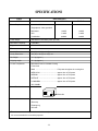
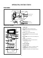
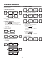
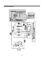
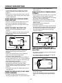
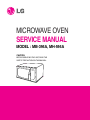
MICROWAVE OVEN
SERVICE MANUAL
MODEL : MB-394A, MH-594A
CAUTION
BEFORE SERVICING THE UNIT, READ THE
SAFETY PRECAUTIONS IN THIS MANUAL.
SPECIFICATIONS
ITEM
DESCRIPTION
MODEL
Power Requirement
MB-394A
MH-594A
Microwave
1,200W
1,200W
Grill
1,100W
1,100W
Combination
2,250W
1,200W
230 Volts AC 50 Hz
Single phase, 3 wire grounded
Power Output
800 Watts full microwave power (IEC705)
Microwave Frequency
2,450 MHz
Magnetron
2M214 - 39F
Timer
90 min.
Outside Dimensions
483 (W) x 285 (H) x 360 (D) mm
Cavity Dimensions
312 (W) x 198 (H) x 316 (D) mm
Net Weight
13.7 kg (approx.)
Shipping weight
15.1 kg (approx.)
Control Complement
Microwave Power for Variable Cooking
Power level
MAX .................................................. Full power throughout the cooking time
MED.-HIGH ........................................ approx. 80% of Full power
MEDIUM ............................................ approx. 60% of Full power
DEFROST .......................................... approx. 40% of Full power
LOW/WARM ...................................... approx. 20% of Full power
Grill, COMBI
Name Plate Location
Back side
Accessories
Owner's manual
Glass tray
Rotating ring
Grill rack
This microwave oven is designed for household use only.
It is not recommended for commercial purposes.
1-1
OPERATING INSTRUCTIONS
FEATURES
Oven Front Plate
Window Door Screen
Door Seal
Display Window
Control Panel
Safety Door Lock System
Glass Tray
Grill Rack
Rotating Ring
CONTROL PANEL
1. INDICATORS
2. SET CLOCK: Used to set the time of day.
3. MICRO: Used to select the desired power level
1
for microwave cooking.
9
4. GRILL: Used to select the grill cooking.
2
10
3
4
11
5. AUTO DEFROST: Used to select the auto weight
defrost.
6. AUTO COOK: Used to cook the foods listed by one
touch.
12
7. TIME: To set cooking times.
8. STOP/CLEAR: Used to stop oven and clear all
entries except time of day.
5
- CHILD LOCK
6
9. DISPLAY WINDOW
10. KITCHEN TIMER
11. COMBI: Used to select the combination cooking.
7
8
12. MORE/LESS: Used to change cooking time.
13
13. START: One tap allows oven to begin functioning.
4-1
OPERATING SEQUENCE
6. GRILL COOKING
The following is a description of component functions
during oven operation.
1. SETTING THE CLOCK
Stop
Set
clock
Stop
Set the
correct hour
Set the
correct minute
Touch
start
Stop
Touch
start
2. CANCEL FUNCTION
Touch the STOP pad whenever you need to
cancel an entry or a function currently in use.
The display will either return to the last item entered
or to the clock.
Desired
combi
category
Desired
cooking Time
Start
Desired
defrost
category
Desired
cooking
Weight
Start
9. CHILD LOCK
This oven has a CHILD LOCK feature
¥ TO SET CHILD LOCK
¥ Touch the
pad
Stop
¥ Touch STOP pad
L appear in
the display.
3. QUICK START
Start
¥TO CANCEL CHILD LOCK
¥ Touch the
pad
Stop
¥ Touch STOP pad
L disappears.
4. MICROWAVE COOKING
Desired
power level
Desired
cooking time
10. AUTO COOK
Start
5. MULTI-STAGE MICROWAVE
COOKING
Stop
STAGE 1
Stop
Start
8. AUTO WEIGHT DEFROST
Stop
Stop
Desired
cooking Time
7. COMBINATION COOKING
NOTE: You can set 12 hour clock or 24 hour clock
optionally.
Stop
Grill
Desired
power level
Desired
cooking time
STAGE 2
Desired
power level
Desired
cooking time
Grill
or Combi
Desired
cooking time
Start
4-2
Desired
auto cook
category
Desired
cooking
Weight
Start
SCHEMATIC DIAGRAM
FOR MODEL MB-394A
4-3
FOR MODEL MB-394AA
4-4
CIRCUIT DESCRIPTION
power of microwave oven as POWER LEVEL.
(refer to page 1-1)
GENERAL DETAILS
¥ The low voltage transformer supplies the necessary
voltage to the micom controller when power cord is
plugged in.
¥ When the door is closed, the primary switch is ON, the
secondary switch is ON, and the monitor switch opens
(contact COM and NO).
WHEN THE DOOR IS OPENED DURING
COOKING
¥ Both the primary switch and relay 2 are cut off primary
winding voltage of the high voltage transformer.
¥ ON-OFF of relay 2 is coupled electrically with opening
and closing of the secondary switch.
¥ When the door is opened, the secondary switch is
opened and when the door is closed, the secondary
switch is closed.
¥ The cooking time stops counting down.
¥ Relay stops functioning.
¥ As the door is opened, if the contact of primary switch
and relay 2 and/or secondary switch fails to open, the
fuse opens due to the large current surge caused by
the monitor switch activation, which in turn stops
magnetron oscillation.
WHEN SELECTING COOKING POWER
LEVEL AND TIME
¥ The micom controller memorizes the function you set.
¥ The time you set appears in the display window.
¥ Each indicator light turns on to indicate that the stage
has been set.
WHEN TOUCHING THE START PAD
¥ The coil of the relay is energized by the micom
controller.
¥ Power input is supplied to the high voltage transformer
through the fuse to the primary switch and relay 2.
¥ Turntable rotates.
FUSE
FUSE
PRIMARY
SWITCH
L
PRIMARY
SWITCH
H.V.
TRANSFORMER
MONITOR
SWITCH
L
N
MONITOR
SWITCH
H.V.
TRANSFORMER
N
RELAY 2
SECONDARY
SWITCH
MICOM CONTROLLER
RELAY 2
SECONDARY
SWITCH
MICOM CONTROLLER
WHEN TOUCHING THE START KEY
WITH THE GRILL COOKING FUNCTION
SELECTED
¥ The fan motor rotates and cools the magnetron by
blowing the air (coming from the intake on the
baseplate).
¥ The air is also directed into the oven to exhaust the
vapor in the oven through the upper plate.
¥ Cooking time starts counting down.
¥ 3.2 volts AC is generated from the filament winding of
the high voltage transformer. This 3.2 volts is applied to
the magnetron to heat the magnetron filament through
two noise-preventing choke coils.
¥ A high voltage of approximately 2100 volts AC is
generated in the secondary of the high voltage
transformer which is increased by the action of the high
voltage diode and charging of the high voltage
capacitor.
¥ The negative 4,000 Volts DC is applied to the filament
of the magnetron.
¥ The contacts of the primary switch and the secondary
switch close the circuit.
¥ A.C. voltage is applied to the grill heater through grill
thermostat as shown by the solid line.
GRILL
THERMOSTAT
L
L
G -Y
N
GRILL
HEATER
E
N
RELAY 3
¥ Turntable rotates.
¥ The fan motor rotates.
¥ The air is also directed into the oven to exhaust the
vapor in the oven through the base plate and upper
plate.
WHEN THE OVEN IS SET AT ANY LEVEL
EXCEPT MAXIMUM.
¥ The micom controller controls the ON-OFF time of
relay 2 by the applied signal to vary the average output
4-5