1
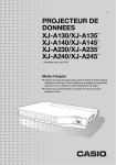
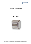
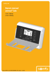
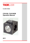
Original Installation and Operating Manual 1 - 17 Tube motor A 10/40, A 10/60, A 20/60, A 30/60, A 40/60, A 50/60, A 60/70, A 80/70 (NHK), A 100/70 (NHK), A 140/70 (NHK), A 230/92 (NHK) 46677V001-312012-0-OCE-Rev.GB Table of contents General Information.....................................................................................2 Safety instructions....................................................................................2 Personal safety equipment.......................................................................3 Intended use.............................................................................................4 Tube motor application table....................................................................4 Technical data..........................................................................................5 Explanation of terms....................................................................................6 Installation.....................................................................................................7 Adapter change........................................................................................7 Installation of tube motor..........................................................................8 Initial operation.............................................................................................10 Setting the end positions with the end switches.......................................10 Emergency release.......................................................................................11 Emergency release of the tube motor with the emergency hand crank................................................................................................11 Electrical connection...................................................................................12 Connection examples...............................................................................13 Troubleshooting...........................................................................................15 Warranty and after-sales service................................................................16 –1 General Information Safety instructions • These installation and operating instructions must be read, understood and complied with by persons who install, use or perform maintenance on the drive. • The manufacturer assumes no liability for injuries, damage or break-downs that occur due to noncompliance with the installation and operating instructions. • Always ensure compliance with accident prevention regulations and current standards in each respective country. • Observe and comply with the Employer’s Liability Rules “Power-operated windows, doors and gates – BGR 232", applicable in Germany. • Installation, connection and initial commissioning of the tube motor may only be carried out by technically knowledgeable persons. • Fasten the tube motor in such a way that it is not a hazard for persons. • Never operate a damaged drive. • Only use OEM (Original Equipment Manufacturer) spare parts, accessories and mounting material. • Before any work on the tube motor disconnect it from the power supply at all poles and lock it to prevent reconnection. • Do not carry the tube motor by the connector cable. • Never reach into moving parts. • If the tube motor is controlled by a controller, a switch or buttons, mount them in a suitable, accessible position. Minimum height above the ground: 1.6 meters. • Moving parts of the tube motor below a height of 2.5 meters must be shielded. • Keep remote controls away from children or animals. Additional instructions for use with roller shutters • Roller shutter cover must be accessible and removable as specified by DIN 18073. • Do not remove the stoppers of the last roller shutter slat. Additional instructions for use with awnings • When the awning is fully extended it must be at least 0.4 meters away from any adjacent objects. • The lowest point of the awning must be less than 1.8 meters high. Additional instructions for use with gates • Do not allow children or persons who have not been instructed to operate the gate control unit. • Open and close the gate only if there are no children, persons, animals or objects within its range of motion. • Actuate the gate wirelessly only if you have an unobstructed view. • Never put your hand near the gate when it is moving or near moving parts. • Drive through the gate only when it has opened completely. • Gates automated with an operator must comply with the valid standards and directives. –2 General Information Personal safety equipment Declaration of Conformity EC Declaration of Installation for the installation of an incomplete machine in accordance with the Machinery Directive 2006/42/EC, Appendix II, Section 1 B SOMMER Antriebs- und Funktechnik GmbH Hans - Böckler - Straße 21 - 27 73230 Kirchheim unter Teck Germany hereby declares that the following products Product identification: Type identification: Tube motor A 10/40, A 10/60, A 20/60, A 30/60, A 40/60, A 50/60, A 60/70, 80/70 (NHK), A 100/70 (NHK), A 140/70 (NHK), A 230/92 (NHK) complieswiththeMachineryDirective2006/42/ECandisspecifiedforinstallationinarollershutter,awning,orgate system. • The following fundamental and relevant safety requirements have been applied and observed in accordance with Appendix I: • Compliant with the regulations of the EC Building Products Guideline 89/106/EC. For the operating forces part, the respective initial testing has been carried out in consultation with recognized inspecting authorities. In doing so, the harmonized standards EN 13241-1, EN 12453 and EN 12445 have been applied. For the tested combinations, refer to the "Reference list" table in the Internet under www.sommer.eu. • Compliant with the Low Voltage Directive 2006/95/EC. • Compliant with the Directive on Electromagnetic Compatibility 2004/1 08/EC. • The technical documentation was drawn up in accordance with Appendix VII B. The product may only be put into operation after it has been established that the door system complies with the regulations of the Machinery Directive. Kirchheim, April 24, 2012 Jochen Lude Responsible for documents –3 Intended use General Information • The drive is intended exclusively for opening and closing roller shutters, awnings and gates up to the area and weight specified by the technical data. The manufacturer accepts no liability resulting from use other than intended use. The user bears the sole responsibility for any risk involved. • The tube motor may only be used if it is in perfect working order and is used as intended, in conscious observation of safety and hazards and in accordance with the installation and operating instructions. • Faults that may affect safety must be repaired without delay. • Only use the tube motor in dry, non-explosive areas. Tube motor application table Shaft diameter [mm] 60x oct. shaft Awning height [m] 2.5 70x oct. shaft 100x round shaft 3 5 3 5 Model Maximum allowable awning in kg A 10 / 40 15 14 13 12 A 10 / 60 18 17 16 15 A 20 / 60 38 35 32 30 A 30 / 60 56 52 48 44 A 40 / 60 75 70 64 58 A 50 / 60 A 60 / 70 94 89 80 70 80 70 A 80 / 70 110 95 A 100 / 70 140 120 A 80 / 70 (NHK) 110 95 A 100 / 70 (NHK) 140 120 A 140 / 70 (NHK) 200 170 330 270 3 4 5 A 230 / 92 (NHK) –4 General Information Technical data Model A 10 / 40 A 10 / 60 A 20 / 60 A 30 / 60 A 40 / 60 A 50 / 60 A 60 / 70 Maximum torque [Nm] 10 10 20 30 40 50 60 Speed [1 / min.] 17 15 15 15 15 12 15 Dimensions Diameter [mm] 35 45 45 45 45 45 59 Length of connector cable [m] 2 2 2 2 2 2 2 Connector cable [mm²] 4 x 0.75 4 x 0.75 4 x 0.75 4 x 0.75 4 x 0.75 4 x 0.75 4 x 0.75 Connected loads Operating voltage [V] 230 V AC 230 V AC 230 V AC 230 V AC 230 V AC 230 V AC 230 V AC Frequency [Hz] 50 50 50 50 50 50 50 Approved operating mode KB 4 min. 4 min. 4 min. 4 min. 4 min. 4 min. 4 min. Model A 80 / 70 A 100 / 70 A80 / 70 (NHK) A100 / 70 (NHK) A140 / 70 (NHK) A230 / 92 (NHK) Maximum torque [Nm] 80 100 80 100 140 230 Speed [1 / min.] 15 9 15 12 Diameter [mm] 59 59 59 59 59 92 Length of connector cable [m] 2 2 2 2 2 2 Connector cable [mm²] 4 x 0.75 4 x 0.75 4 x 0.75 4 x 0.75 4 x 0.75 4 x 0.75 12 Dimensions Connected loads Operating voltage [V] 230 V AC 230 V AC 230 V AC 230 V AC 230 V AC 230 V AC Frequency [Hz] 50 50 50 50 50 50 Approved operating mode KB 4 min. 4 min. 4 min. 4 min. 4 min. 4 min. –5 Explanation of terms 4 5 3 2 1 6 7 9 8 * Example illustration: The wall anchors for the drive can be ordered at any time from SOMMER Antriebs- und Funktechnik GmbH. 1. Wall anchor * 2. Connector line 3. Screw 4. Motor bearing 5. End switch catch ring 6. Tube motor 7. Motor clutch 8. Controller (accessory) 9. Retaining pin –6 Adapter change Installation Install the right adapter before installation of the winding shaft, precision tube, etc. Removing adapter 1 1 2 2 3 1. Remove retaining spring (use circlip pliers for the specific tube motor). 2. Slide the adapter from the tube motor axle. 3. Slide adapter down at the end of the tube motor (motor side). Install adapter. 1 2 2 3 3 1. Push adapter at the motor side to the end. Make sure that the slot on the adapter and the tube motor is correctly positioned. 2. Slide the adapter on to the tube motor axle. 3. Position retaining spring (use circlip pliers for the specific tube motor). –7 Installation Installation of tube motor 1 2 –8 Installation Risk of motor dropping if not correctly installed! ! If the tube motor is not correctly fastened to the wall, there is a risk that it will fall. This may cause serious injury. • Always screw the tube motor in position correctly and use the locking pin. Note ! Use only approved construction fasteners (e.g. anchor fittings, bolts). The fasteners must be suitable to the material of the ceilings and walls. Note ! Note the thermal expansion of the shaft! Allow 1-2 mm of space for expansion during installation 1. Insert tube motor in wall anchor and lock in wall anchor with locking pin or bolt tube motor directly to the wall. -- Note the position of the connector line - always down! Only tube motor A 230 / 92 (NHK): connector line up. -- Note the position of the end switch - easily accessible! -- Only NHK models: Note the position of the emergency hand crank - easily accessible! 2. Always install tube motor horizontally and check with a spirit level. Note ! All cables must be shielded and permanently installed. Always install connector cable with a slack loop to prevent penetration of condensation along the cable. Do not kink cables and install them where they cannot be damaged by moving parts. –9 Initial operation Note! The end shutoff only operates if the tube motor with the adapter set is installed in a winding shaft / precision tube. The tube motor has a run time of approx. 4 minutes, then the thermostat switches it off for safety. The tube motor can be operated again after approx. 15 minutes. Setting the end positions with the end switches All tube motors have mechanical end switches that are used to set the end positions. Set the end positions with the included setting tool. The arrows show the direction rotation of the motor. The arrows show the direction rotation of the motor. • Rotation in the (+) direction • Rotation in the (+) direction extends extends the travel distance. the travel distance. • Rotation in the (-) direction • Rotation in the (-) direction reduces reduces the travel distance. the travel distance. – 10 Emergency release Note ! The tube motor emergency release is only available in NHK models, such as the A 100 / 70 NHK tube motor. The emergency release is only suitable for opening or closing the roller shutter, awning or gate in case of an emergency, e.g. a power outage or failure of the tube motor. The emergency release is not designed for frequently opening or closing the roller shutter, awning or gate. This may damage the tube motor. Emergency release of the tube motor with the emergency hand crank Risk of crushing if tube motor starts unexpectedly! Hands, long hair and loose clothing may be trapped and crushed. • Disconnect the tube motor from the power supply before emergency release. 1. Fasten the emergency hand crank to the tube motor. 2. Open or close the roller shutter, awning or gate by turning the crank. – 11 Electrical connection Attention! In case of direct or indirect contact with live parts, current could flow through the body. Electrical shock, burns, or death may result. • Connection must be made by an electrician only. Tube motors must not be connected in parallel (note max. switching capacity of the terminal). Note ! All cables must be shielded and permanently installed. Always install connector cable with a slack loop to prevent penetration of condensation along the cable. Do not kink cables and install them where they cannot be damaged by moving parts. • Use only locked switches or buttons. • Request the documentation for installing controllers from the controller manufacturer. • Observe the regulations of the VDE and local power supply companies and also the regulations for wet and moist areas of VDE 0100 for connections. • Installations must include the option of disconnecting all poles from the power supply, e.g. two-pole switches with min. 3 mm contact opening width or all-pole main switches. Note! The motor actuators must be interlocked in the up and down direction. A switchover delay of at least 0.5 seconds must be guaranteed. – 12 Electrical connection Connection examples Single-drive controller M 4 x 0,75 mm 2 Power 230 V / 50 Hz Venetian blind switch Single drive via RDC 800 / RDC Vision M 4 x 0,75 mm 2 Power 230 V / 50 Hz RDC 800 / RDC Vision – 13 Electrical connection Single-drive time / light controller M 4 x 0,75 mm 2 Power 230 V / 50 Hz Light sensor ContRoll Astro also available with ContRoll Touch! Two (or more) drives via common time clock M M M M 4 x 0,75 mm Power 230 V / 50 Hz F (10A) Power 230 V / 50 Hz Isolating relay Light sensor ContRoll Astro also available with ContRoll Touch! – 14 2 Troubleshooting Fault Possible causes Corrective action Tube motor does not move. No supply voltage. Check electrical fuse. Connection fault. Connect tube motor correctly, see „Connection examples“ on page 13. Connector cable damaged. Check connector cable for any damage. Thermostat has tripped and switched off the tube motor for safety. Caution! Tube motor may be very hot! One direction of rotation is blocked. Run tube motor in the functional direction for at least one second, then in the required direction. An end switch has been reached. Correct end switch position, see „Setting the end positions with the end switches“ on page 10. Tube motor runs in the wrong direction. The wires of the motor actuators are reversed in the up and down direction. Reverse the wires of the motor actuators in the up and down direction. Tube motor switches off / remains stopped. Roller shutter, awning or winding shaft does not run smoothly. Check that the roller shutter, awning or winding shaft runs smoothly. Obstacle in the path of the roller shutter, awning or winding shaft. Remove obstacle. An end switch has been reached. Correct end switch position, see „Setting the end positions with the end switches“ on page 10. Shaft does no longer drives end switch catch ring. Check installation of tube motor. Tube motor only runs in one direction. Specified end position no longer applicable. – 15 Allow tube motor to cool for at least 15 minutes. Warranty and after-sales service The guarantee complies with the legal regulations. Contact your specialist dealer if there are any guarantee issues. The warranty is only valid in the country in which the product was purchased. Batteries, fuses and bulbs are excluded from the warranty. If you require after-sales service, spare parts or accessories, please contact your specialist retailer. We have tried to make the Installation and Operating Instructions as easy as possible to follow. If you have any suggestions as to how we could improve them or if you think more information is needed, please send your suggestions to us: Fax.: 0049 / 7021 / 8001-403 email:[email protected] Disassembly Observe safety information. The sequence is identical to that described in the “Installation” section, but in reverse order. Ignore the setting instructions. – 16 SOMMER Antriebs- und Funktechnik GmbH Hans-Böckler-Str. 21-27 D-73230 Kirchheim unter Teck