1
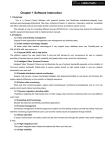
ANTARIS SOLAR
INSTALLATION & MAINTENANCE
MANUAL FOR PV MODULES
LIVING BY THE SUN!
Preface
This manual offers the general installation and maintenance information of the Photovoltaic Modules (hereinafter referred to
as the Modules) of ANTARIS SOLAR GmbH (hereinafter referred to as ANTARIS SOLAR). Before installation, handling or
application of maintenance, ensure yourself read and understand this manual and use the Photovoltaic Modules correctly &
safely. If you have any questions, please feel free to contact the sale’s manager of ANTARIS SOLAR or our Customer Service.
General use
1. The operators shall foresee the injury risk during the processes of installation, debugging and maintenance of the Modules; Therefore, these processes shall be accomplished by the professionals with appropriate qualifications.
2. Do not dismantle the Modules or tear up any labels.
3. Do not touch the exposed cables or connectors.
4. After open the packing, an opaque cloth or other materials shall be used to cover the frontage of the Modules for the reason that monolithic module may produce potentially fatal current or voltage in the direct sunlight.
5. System designers and installers shall design a reasonable bracket, Fix the module on the bracket according to the recommended method (Please refer the 9th point of the Installation part).
6. The installation, debugging and maintenance of the Modules etc must be complied with all the electrical engineer safety regulations.
7. In the standard test condition (the standard test condition is: irradiance of 1000 W/m2, battery tag temperature of 25°C and spectrum of AM1.5), the electrical performance parameters of the Modules, such as Isc, Voc and Pmax have a ±10% deviation with the nominal value.
8. Do not trample or strike on the Modules.
9. Do not spray the chemical non-validated or paints on the modules.
10.When operating the change of any module or in case of maintenance, please take necessity actions to avoid the possible electrical injuries.
MANUAL I 2
LIVING BY THE SUN!
Transport and Carry
1. Carry the Modules carefully and handle them on respecting of instruction.
2. Keep the Modules away from inflammable gas, hazardous chemicals or fire source.
3. Do not carry wet Modules.
4. It is highly recommended to transport with container and the unfilled space (the gap over 20cm) shall be filled with inflatable bag; As for the non-container transport, the Modules shall be single laid and wholly cared, and some effective measures shall be taken to prevent displacement.
5. The surface oxide layer of the border may be scratched by sharp objects, do not destroy or scratch the border of the Modules.
Installation
1. Installers must be qualified engineers and familiar with electrical and its applications.
2. Do not use damaged Modules. Damaged Modules may cause fire or electric shock; both the two results could cause the death of the user or installer.
3. Do not disconnect the cable under a load circumstance.
4.
Under normal conditions, a Photovoltaic Module may be able to produce voltage and current higher than in standard test condition. Accordingly, when determining component rated voltage, conductor ampacities, fuse current and size of controls connected to the PV output, the short circuit current and open circuit voltage value marked on this module shall be multiplied by a factor (safety factor) of 1.25.*
5. The Modules shall be installed in the position of the sun exposures fully and to ensure that not to be shaded by trees, buildings or something others surrounding, such as in the northern hemisphere installed towards the south and in the southern hemisphere installed towards the north.
6. Use the bracket structure that could withstand the pressure of high winds or heavy snow according to your practical installation condition. The bracket structure must be made of durable, corrosion resistant, UV resistant materials.
7. The installation structure must be designed by registered professional engineers, and installation design and procedures shall be consistent with the local relevant provisions.
8. You could choose either fixing method mentioned below per the actual condition: Screw-fixing system (Drawing 1-a), Fixture-fixing system (Drawing 1-b) or Inserting System.
SCREW BOLT
MODULE FRAME
FLAT GASKET
FLAT GASKET
SPRING WASHER
SCREW NUT
MOUNTING STRUCTURE
Drawing 1-a Installed by nut and bolt
Drawing 1-b Installed by fixture
* Note: The safety factor for component rated voltage, conductor ampacities, fuse current and size of controls connected to the PV output is subject to the meteorological conditions of project sites.
MANUAL I 3
LIVING BY THE SUN!
9. Installation method and location
A) Screw-fixing: fix the modules on the bracket on the bracket at 8 border prefabricated installation holes (Drawing 2).
Standard installing hole
installing hole for strong
wind and heavy snow
Drawing 2 Screw-fixing
B) Fixture-fixing: Fix the module safely and effectively on the brackets with special installation tools
a ) For a Series (156-72) modules, Six clamps must be used (Drawing 3)
L
L/8 ≤ e ≤ L/4, a ≥ 8 cm
Drawing 3-a on long frame
a
e
e
L/2
w
e
L
e
w/8 ≤ e ≤ w/4, a ≥ 8 cm
Drawing 3-b on short frame
L/2
MANUAL I 4
LIVING BY THE SUN!
a ) For other series module, fix the module with the long side (Drawing 4-a) or short side (Drawin 4-b) according to the bracket designation and mechanical load requirement.
L
L/8 ≤ e ≤ L/4, a ≥ 6 cm 2400 Pa
Drawing 4-a fixing on the long side
for the other module series
a
e
e
L
L/8 ≤ e ≤ L/4, a ≥ 6 cm 5400 Pa
Drawing 4-a fixing on the long side
for the other module series
a
L/2
e
e
a
w
e
e
w/8 ≤ e ≤ W/4, a ≥ 6 cm 2400 Pa
Drawing 4-b fixing on the Short side
for the other module series
MANUAL I 5
LIVING BY THE SUN!
w
e
L
e
a
w/8 ≤ e ≤ W/4, a ≥ 6 cm 5400 Pa
Drawing 4-b fixing on the long side
for the other module series
L/2
C) Inserting System: Fx the module with U type groove or flange beam
a ) All available installation method for A series modules (156-72) (Drawing 5)
Drawing 5 fixing with sideway
for A series modules
a≥8cm
L/2
Drawing 5 fixing with sideway
for A series modules
MANUAL I 6
LIVING BY THE SUN!
a ) For other series module, fix the module with the long side or short side according to the bracket designation and mechanical load requirement. (Drawing 6)
2400 Pa
Drawing 6 fixing with sideway for
the other module series
5400 Pa
Drawing 6 fixing with sideway for
the other module series
a≥6cm
L/2
5400 Pa
Drawing 6 fixing with sideway for
the other module series
Anyway fix eight installation holes simultaneously is recommended according to the Security Considerations. In the correct installation method, the Modules could maximumly bear snow pressure of 5400 Pa or wind pressure of 2400 Pa.
MANUAL I 7
LIVING BY THE SUN!
10.When installing the Modules on the roof, ensure there is an appropriate structure, and a suitable seal shall be made between the Modules and the bracket to prevent leaking.
11.Installing the Modules on the roof may affect the fire rating of the house which requires the construction organization to make more accurate assessment.
12.The grounding method shall be consistent with the local standard and regulations. The grounding wire shall be the bare copper wire with simple surface treatment and no insulation sleeve. Wire cable with cross-sectional area of 4~6 mm2 (10~12 AWG) and ground clamp (Tyco, identification of product: 1954381-2) are recommended (diagrammatic sketches are as follows).
Installation
2
1
4
5
3
Drawing 7 Grounded with Ground clamp
13.When the connecting wire of the Modules can not meet system design requirements, a proper commercial cable that could endure long-term outdoor use and assorted connector could be used to extend the connecting wire. The cross-sectional area shall be no less than 4 mm2, and the connection system shall reach IP65 protection rating.
14.The minimum separation between two Modules shall be more than 10 mm; when installing on the roof, the minimum separation between the Modules and the mounting surface shall be more than 150 mm, and when installing on the ground, more than 450 mm.
15.It had better to use the Modules with same configuration in a series connection system.
16.Artificially concentrated sunlight shall not be directed on the module.
17.Our modules have passed the salt mist and ammonia test (Please refer the test report for detailed information) and can be installed in some brutal environment, e.g. sea side.
18.The modules should not be installed at the place which is less than 100 meters from the seashore. If the distance of the seashore and the project site is 100~1000 meters, anti-corrosion application should be taken during the installation and grounding processes.
MANUAL I 8
LIVING BY THE SUN!
Product identification
Nameplate: describes the product model; rated power; rated current, rated voltage, open circuit voltage, and short circuit
current. All above parameters are measured in standard test conditions. Other information, such as weight, size, maximum
system voltage and maximum fuse current are marked on the nameplate as well. Barcode: the barcode is in the internal of
the Modules, which containing the relevant retrospect information of the Modules.
! Please do not remove any label, or ANTARIS SOLAR will not provide any warranty.
Maintenance
1. Do not touch the live part of the wire cable and the connector. When touching, use the safety equipment (insulating tool, insulating gloves etc).
2. When maintaining the Modules, use opaque cloth or other materials to cover the frontage of the Modules. Exposed in sunlight, the Photovoltaic Modules may produce high voltage, which is a potential danger.
3.
Cleaning instruction
Periodic cleaning is necessary for solar module, which could reduce the loss due to dust and is recommended by ANTARIS SOLAR. The cleaning processes should be accomplished by the professionals with appropriate qualifications. When cleaning the module surface,
a) Rules shown as below must be followed:
• Only at low irradiance, the cleaning process could be applied.
• Only soft cloth or sponge could be used to clean the glass surface.
• Only clean water could be used as the cleaning solvent.
• The discrepancy between water temperature and module temperature should be in the range of -5°C to +10°C.
• Water pressure should be less than 1000 Pa.
• Necessary electrical protection should be taken.
b) Following notes should be taken into account:
• No other chemical could be used in cleaning process.
• No aggressive tool or coarse material is permitted.
• Do not trample or strike on modules.
• In cleaning process, the modules must not be under a load circumstance.
• Do not touch exposed cables or connectors.
• Forbidden to remove dust in dry way.
• Forbidden to clean modules before cooling down.
MANUAL I 9
LIVING BY THE SUN!
Annual inspection
1. Check if nuts, bolts of mounting structure are secure and not loose. Tighten the loose component again, if required.
2. Check the water resistance of the connecting cables, grounding cables and connectors and the performance of the ground resistance.
3. Check all electrical and mechanical connections from freedom of corrosion.
4. Check the ground resistance of metal parts such as the module frames and the mounting structures.
Disclaimer of Liability
1. The use of this manual and installation, handling, maintenance and use of modules are beyond ANTARIS SOLAR’s control, and ANTARIS SOLAR does not assume any responsibility for loss, damage, injury or expense resulting from such installation, handling, use or maintenance.
2.
ANTARIS SOLAR assumes no responsibility for any infringement of intellectual property right (including without limitation patent, copyright and trademark) or other rights of third parties that may result from use of modules. No license in connection with intellectual property right (including without limitation patent, copyright and trademark) or other rights of ANTARIS SOLAR, whether expressly or impliedly, is granted to customer because of use of modules.
3.
All information stated in this manual is based on ANTARIS SOLAR’s knowledge and experience, but no warranty about such information (including modules specifications) is made by ANTARIS SOLAR, whether expressly or impliedly. ANTARIS SOLAR reserves the right to update this manual, modules specifications or relevant information without prior notice.
MANUAL I 10
LIVING BY THE SUN!
ANTARIS SOLAR GmbH & Co. KG
Head office
63735 Aschaffenburg, Germany
Phone:
Fax:
Email:
Internet:
+49 (0) 6095 950-441
+49 (0) 6095 950-544
[email protected]
www.antaris-solar.com
Member of: