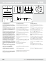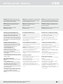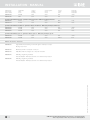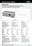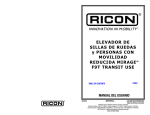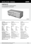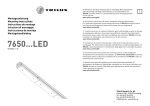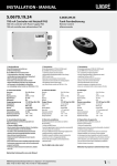
1
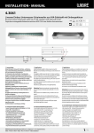
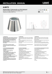
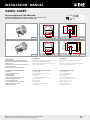
Installation · Manual 4.0302 · 4.0097 Aussenstrahler aus V4A-Edelstahl V4A IP67 EDELSTAHL Outdoor-Floodlight out of marine grade 316L stainless steel Projecteur d’illumination Extérieur en INOX 316L KABEL 152 152 232 265 180° 183 EXCL EXCL 180° 232 183 177 232 265 265 20 4.0302 60 4.0302 60 152 236 232 265 180° 183 180° 232 183 177 265 232 265 20 4.0097 60 4.0097 60 1. Anwendung Aussenstrahler besonders geeignet für die Beleuchtung von Bäumen, Architektur, Skulpturen im privaten, öffentlichen und industriellen Bereich. Verschiedene Zubehörteile (z.B. Farbscheiben, Anti-Blendraster, Betriebsgeräte) sind lieferbar. Sonderkonstruktionen-/anwendungen auf Anfrage. 1. Application Outdoor floodlight, especially appropriate for trees, arcitecture, sculptures and trees in private, commercial and industrial areas. Several accessories are available (colour panes, louver, control-gears.) Special constructions on demand! 1. Utilisation Projecteur d‘illumination pour l‘éclairage des architecture, sculptures et arbres. Plusieurs accessoires disponible (verres de couleur, grilles, alimentations). Constructions sur mesure sur demande possible! 2. Technische Daten/Konstruktion · Schutzart IP67 · komplett aus V4A-Edelstahl gefertigt · mit Aluminium-Reflektor · Leuchtmittel: für Halogen · Sonderverschraubung PG16/21, Messing vernickelt · temperaturbeständige Silikondichtung · gehärtetes Sicherheitsglas (ESG) · Vorschalt- und Zündgerät je nach Version eingebaut · mit Befestigungswinkel 180° verstellbar · Nur Silikonkabel verwenden 2. Technical Details/Construction · Protection system IP67 · Made entirely of marine grade 316L stainless steel · with aluminium reflector · b ulbs: for halogene · Special cable gland PG 16/21, nickel-plated brass · Temperature-resistant silicon seal · Toughened safety glass · Ballast and ignitor fitted · or mounting bracket adjustable through 180° · o nly use silicon cable 2. Technique/Construction · Indice de protection IP67 · Complet, en acier inoxydable V4A, 316L · avec réfl ecteur en aluminium · source: pour hologene · Presse-étoupe spécial PG16/21, laiton nickelé · Joint en silicone résistant aux températures élevées · Verre de sécurité trempé (monocouche) · Ballast et amorceur intégré · avec étrier de fixation 180° · utiliser uniquement câble en silicone WIBRE Elektrogeräte Edmund Breuninger GmbH & Co. KG · Liebigstrasse 9 · 74211 Leingarten/Germany Telefon: +49 (0) 7131 9053-0 · Telefax: +49 (0) 7131 9053-19 · E-Mail: [email protected] 1/4 Installation · Manual ø 6,5 ø 6,5 5,6 ø 8,5 A ø 6,5 F D 1 2 C G 3 H B 4 16 3.2 120 3.3 E 3.4 5 6 NL 7 8 9 10 3.1 3. Installation/Montage Zur Installation sind die nationalen Sicherheitsvorschriften zu beachten. Es wird keine Haftung für unsachgemäßen Einsatz oder Montage übernommen. Bei nachträglichen Änderungen wird keine Haftung übernommen. Befestigungsbügel bzw. Befestigungswinkel ist entsprechend der Zeichnung 3.2/3.3 fest am Untergrund zu verschrauben, hierfür sind ausschließlich entsprechende V4A Edelstahlschrauben zu verwenden, da sonst Korrosion an den Scheinwerferteilen entstehen kann. NUR Silikonkabel verwenden, falls nicht im Lieferumfang enthalten. Zum Anschluss des Kabels den Scheinwerfer laut Zeichnung 3.1. öffnen und Glas (4), Dichtung (5;6), Reflektoreinsatz entfernen. Kabelverschraubung am Scheinwerfer öffnen; Druckschraube, Silikondichteinsatz entfernen und über Silikonleitung führen, in Kabelverschraubung eindrücken und Druckschraube fest anziehen. Achtung: Nur Silikonleitung mit Außendurchmesser von 9–13 mm verwenden, andere Durchmesser durch Austausch des Silikondichteinsatzes möglich. Einzelanschlussader entsprechend der Vorschriften an Anschlussklemme elektrisch anschließen und Schutzleiterverbindung vornehmen. Reflektor-/ Leuchteneinsatz montieren und Leuchtmittel einsetzen (sofern nicht im Lieferumfang). Silikonflachdichtung (6), Silikonstufendichtung (5), Glasscheibe (4), Papierdichtung (3), Blendring(6), Schrauben (1) laut Zeichnung 3.1. auf Scheinwerfergehäuse auflegen und kreuzweise gleichmäßig verschrauben 3.5. (empfohlenes Anzugsdrehmoment 3,0 Nm). Es ist auf gleichmäßigen, festen Sitz der Schrauben zu achten. Diese sollten nach ca. 4 Wochen Betrieb der Leuchten kontrolliert und mit empfohlenen Drehmoment nachgezogen werden. Funktionsprobe des Scheinwerfers kurz durchführen. Befestigungsfuß am Scheinwerfergehäuse verschrauben und Scheinwerfer auf Objekt ausrichten. Befestigungsfuß am Schein werfergehäuse nach Ausrichtung erneut fest verschrauben. Achtung: Nur richtig eingelegte Dichtungen, Gläser, Abschlussblenden und richtig angezogene Schrauben sowie empfohlenes Kabel und fest angezogene Kabelverschraubungen gewährleisten den einwandfreien Scheinwerferbetrieb. 2/4 3.5 3. Installation/Mounting The national legislation with respect to safety must be observed for installation. We are not liable for any improper use or installation. In the event of any retrofit modifications, we shall not be held liable. Mounting brackets and mounting angles must be fixed solidly on the ground (see drawing 3.2/3.3), only stainless steel screws can be used, otherwise corrosion on parts of the floodlight could occur. Only use silicon cable, if not already supplied together with the floodlights. When connecting the cable to the floodlight, open the floodlight D as described on drawing 3.1 and remove glass (4), gaskets (5;6) and the reflector. Open the floodlight‘s cable gland, remove pressure screw, G and silicon gasket, pull everything along the connecting cable and press it into the cable gland, tighten the screw cable gland solidly. Precaution: Only use silicon cables with an exterior diameter of 9–13 mm, other diameters can only be used, when changingB the silicon gasket. E Make electrical connection with the single wires, as well as the earth conductor connection. Insert the reflector, and put the bulb into it, if not already supplied with the floodlight. Mount silicon flat gasket (6), rippled silicon gasket (5), glass pane (4), paper AFM gasket (3), cover frame ring (6), screws (1) as shown on drawing 3.1. onto the floodlight and tighten them firmly crosswise. (torque =3 Nm). Make sure that all screws are solidly and firmly placed! Make a quick operation test. Observe and screw the screws once again after one month of operation.(torque 3 Nm) Screw the mounting foot onto the floodlight and orientate it towards the object which needs to be illuminated. Observe and screw the screws once again after one month of operation. (torque 3 Nm) Screw the mounting foot once again solidly onto the floodlight, after orientation of the floodlight has been done. 3. Installation/Montage Respecter les prescriptions nationales applicables en matière de sécurité. Nous déclinons toute responsabilité pour l’utilisation ou le montage non conforme. En cas de modification a posteriori sur le projecteur, nous déclinons toute responsabilité. Fixer l‘étrier de montage ainsi que l‘angle de montage au fond du projecteur (voir dessin 3.2/3.3), pour cette installation utiliser que de vis Inox V4A, pour éviter le risque de corrosion.S‘assurer du bon serrage de l‘ensemble! Utiliser queFde câble silicone, si ne déjà encore livré avec. Pour le raccordement du câble au projecteur, ouvrir le projecteur (voir dessin 3.1), enlever le verre (4), le joint (5,6) et le réflecteur. Ouvrir le presse-étoupe C du projecteur, enlever la vis de pression, joint de pression, tirer l‘ensemble sur le câble en silicone, presser l‘ensemble dans le presse-étoupe et resserrer bien la vis de pression. Attention: Uniquement utiliser du câble en silicone avec un diamètre H9–13 mm, autres diamètres sont possibles si on change le joint extérieur du de pression. Enfiler les gaines de silicone et faire le raccordement électrique, mettre à la terre.Monter le réflecteur et insérer l‘ampoule, si elle n‘était déjà livrée avec. Poser joint en silicone (6), joint en silicone épaulé (5), verre (4), joint AFM en papier (3), anneau de l‘enjoliveur (2) et les vis (1) sur le projecteur, et serrer les vis en croix et fort.(moment de serrage=3 Nm) (voir dessin 3.1).S‘assurer d‘une pose de vis solide et équilibré. Contrôler et revisser les vis après un mois d‘utilisation selon le moment de serrage (3 Nm) Faire un court test de fonctionnement du projecteur hors de l‘eau. Visser le pied de fixation sur le projecteur et orienter le vers l‘objet à éclairer. Visser le pied de fixation encore une fois fortement après l‘orientation du projecteur a été fait. Attention: Seul les joints, vitres, enjoliveurs correctement mis en place et les vis correctement serrées ainsi que l’utilisation du câble recommandé et des presse-étoupes serrée garantissent le fonctionnement du projecteur. . Attention: Only properly inserted seals, glass panes, covers and properly tightened screws, as well as the recommended cable and securely tightened cable screw fixtures ensure proper light operation. WIBRE Elektrogeräte Edmund Breuninger GmbH & Co. KG · Liebigstrasse 9 · 74211 Leingarten/Germany Telefon: +49 (0) 7131 9053-0 · Telefax: +49 (0) 7131 9053-19 · E-Mail: [email protected] Installation · Manual Achtung: Anschluss der Netzteile muss stromlos erfolgen, da sonst Entladungen im Netzteil zur Schädigung der LED führen können. Es darf keine Primärspannung anliegen. Attention: The power supply must be connected without power, since otherwise discharges in the power supply unit may damage the LED. Primary voltage must not be present. Attention: Les blocs d‘alimentation doivent être raccordés hors tension, sinon des décharges dans le bloc d‘alimentation peuvent détériorer les LED. Aucune tension primaire ne doit être présente. Hinweis: Die Installation eines bauseitigen Überspannungsschutzes nach DIN VDE 0100-443, DIN VDE 0100-534 und EN 62305 wird empfohlen. Note: Installation of customised surge protection in accordance with DIN VDE 0100-443, DIN VDE 0100-534 and EN 62305 is recommended. Remarque: L‘installation d‘un système anti-surtension local conforme aux normes DIN VDE 0100-443, DIN VDE 0100-534 et EN 62305 est recommandée. Hinweis: Nur Edelstahlwerkzeug verwenden! Zur Vermeidung von Fremdrost! Note: Only use tools made of stainless steel! To avoid extraneous rust! Remarque: L‘utilisation d‘outils en acier inoxydable est obligatoire! Pour éviter que la corrosion se forme! 4. Wartung und Leuchtmittelwechsel Scheinwerfer spannungsfrei schalten und Gehäuse wie oben beschrieben öffnen. 3.1. Leuchtmittel durch identisches austauschen und Gehäuse laut Vorschrift wieder verschließen 3.4. Hierbei Dichtungen zwischen Glas und Gehäuse und in der Kabelverschraubung auf Abnutzung oder Beschädigung überprüfen und gegebenenfalls wechseln. Verunreinigungen und Ablagerungen auf Glas oder Edelstahlteilen sind mit handelsüblichen Reinigungsmitteln zu entfernen. 4. Relamping and Maintenance Always dismantle and assemble the floodlight and open it as described above 3.1.Change the lamp with an identical one and close as described above. 3.4 Make sure that the gaskets in between glass and housing and the ones in the cable gland are in a good condition, make sure that there is no dirt on the gaskets, if damaged change them immediately. Soiling on the floodlight should be removed frequently by using commercial stainless steel cleansers. 4. Maintenance et changement de lampe Mettre le projecteur hors circuit et ouvrir le boîtier comme expliqué ci-dessus (voir dessin 3.1) Changer l‘ampoule avec une ampoule identique et serrer le projecteur comme indiqué.(voir dessin 3.4) Observer soigneusement les joints entre le verre et le boîtier et ceux au presse-étoupe, changer les s‘ils sont abîmés ou pourris. Il est nécessaire de nettoyer régulièrement les parties en Inox et de les débarrasser des dépôts et souillures avec un produit courant d‘entretien de l‘Inox. 5. Allgemeine Wartungshinweise • Beim Reinigen darf die Leuchte nicht mit Metall angreifenden Reinigungsmitteln in Berührung kommen. Der Einsatz salzsäure haltiger Reinigungsmittel an und in der Nähe von Scheinwerfer teilen aus Edelstahl ist in jedem Fall zu unterlassen. • Scheinwerfer regelmäßig reinigen, um Fremdrostablagerungen zu vermeiden. • Achtung: Keine Hochdruckreiniger verwenden. • Strahler vor Einfrieren schützen, gegebenenfalls müssen diese demontiert oder speziell geschützt werden. • Verloren gegangene Schrauben dürfen nur durch Schrauben aus V4A ersetzt werden. • Je nach Beanspruchung (Höhe der Watttage) ist alle 5–8 Jahre ein Wechsel der Dichtungen (Glasscheibe, Verschraubung, O-Ring) und der Kabel zu empfehlen. 5. General Maintenance indications • A void all contact with metal corroding cleaning agents or acids. The use of acidic cleaning agents on or near spotlights constructed out of stainless steel must be avoided at all time. • C lean regularly spotlights to avoid the build of extraneous rust deposits. • A ttention: Do not use steam jets for cleaning. • F loodlights must be protected against freezing during winter time, should the occasion arise also be taken off and protected separately. • L ost screws may only be replaced by V4A screws. • D epending on the demands of the floodlight(wattage), every 5–8 years, gaskets(glass panes, cable glands, silicon rings) and the cables should be changed. 5. Indications d‘entretien générales • En nettoyant, le projecteur ne doit pas venir en contact avec l‘acide ou des produits de nettoyage qui rongent le métal. • L‘application de produits de nettoyage avec l‘acide chlorhydrique dessus et á proximité des projecteurs en Inox doit être omise dans tout cas. • Nettoyer régulièrement les projecteurs pour éviter des dépôts de rouille par le contact avec des matériaux étrangers. • Attention: Ne pas utiliser un émetteur de vapeur pour le nettoyage. • Protéger les projecteurs contre le gel, si nécessaire démonter et protéger séparément pendant l‘hiver. • Des vis perdues ne peuvent être remplacées que par des vis V4A. • Selon l’exigence (puissance du wattage), tous les 5–8 ans un changement des joints de vitre, de serrage et des câbles doit être prévu. 6. Garantiebestimmungen Folgende Garantiezeiten und Bestimmungen gelten vom Tage der Lieferung an: • 24 Monate auf WIBRE-Scheinwerfer. • Von den Garantieansprüchen ausgenommen sind Leuchtmittel • Unter die Garantie fallen nachweisbare Material-, Konstruktionsund Verarbeitungsfehler vonseiten des Herstellers. • Für Schäden, welche durch Nichtbeachtung dieser Betriebsanleitung, oder durch unsachgemäße Reparatur entstehen, können wir keine Garantie übernehmen. • Keine Garantie besteht, wenn die Installation nicht korrekt nach den Bestimmungen vorgenommen wurde oder bei Verwendung nicht geeigneter Leuchtmittel bzw. Anschlusskabel. • Änderungen, die dem technischen Fortschritt dienen, behalten wir uns vor. 6. Warranty conditions The following warranty conditions are valid on from the day of delivery: • 24 months on WIBRE underwater floodlights • lights bulbs are excluded from warranty • p roven faults appertaining to material, construction or processing fall under the warranty of the manufacturer •w e don‘t accept any liability for damages arising through negligence of these operating instructions or for improper repair work • n o liability is accepted for installation carried out contrary to these instructions or for the use of inappropriate bulbs or cables •w e reserve us the right to instigate any technical improvements without prior notice WIBRE Elektrogeräte Edmund Breuninger GmbH & Co. KG · Liebigstrasse 9 · 74211 Leingarten/Germany Telefon: +49 (0) 7131 9053-0 · Telefax: +49 (0) 7131 9053-19 · E-Mail: [email protected] 6. Dispositions de garantie Des périodes de garantie et dispositions suivantes sont en vigueur au jour de la livraison: • 24 mois pour les projecteurs WIBRE • les sources sont exclues des exigences de garantie • sous la garantie tombent les erreurs de construction démontrables, de matériel et de traitement de la part du fabricant • ne sont pas garantie le non-respect du manuel ou une réparation inadéquate, ainsi que les dommages d‘une fausse manipulation. • aucune garantie n‘existe si l‘installation n‘a pas été entreprise correctement ou pour l‘utilisation des sources et/ou des câbles non appropriés. • dans un but d‘amélioration technique, la société WIBRE se réserve le droit de modifier ces produits 3/4 Installation · Manual Artikelnummer Article number Numéro d’article Leuchtmittel Lamps Source Leistung Wattage Puissance Spannung/Strom Tension Tension Fassung Socket Culot Temperatur Temperature Température 4.0302.10.35 4.0302.10.50 HIT-CRI HME 35W 50W 230V 230V G12 E27 <75°C 90°C RX7s RX7s 110°C 110°C Symmetrischer Reflektor, flood 80° · Symmetric reflector, flood 80° · Réflecteur symétrique, flood 80° 4.0097.12.70 HIT-DE 70W 230V 4.0097.12.71 HST-DE 70W 230V Symmetrischer Reflektor, medium 35° · Symmetric reflector, medium 35° · Réflecteur symétrique, medium 35° 4.0097.16.35 HIT-CRI 35W 230V G12 4.0097.16.52 HST-CRI 50W 230V GX12-1 4.0097.16.70 HIT-CRI 70W 230V G12 <75°C 80°C 110°C Symmetrischer Reflektor, spot 12° · Symmetric reflector, spot 12° · Réflecteur symétrique, spot 12° 4.0097.13.35 HIT-CRI 35W 230V 4.0097.13.52 HST-CRI 50W 230V <75°C 80°C G12 GX12-1 Zubehör · Accessories · Accessoires doppelte Kabelverschraubung · double cable gland · double presse etoupe Messing · brass · laiton 4.0003.01.00 Blendraster, schwarz · louver, black · louver, noir 4.0230.01.00 matte Glasscheibe · frosted glass disc · disque de verre satiné 4.0009.00.20 Winkelring · angular ring · Collerette mit 2 Schutzstäben · with 2 protection bars · avec 2 barreaux de protection 4.0009.00.40 Winkelring · angular ring · Collerette mit 4 Schutzstäben · with 4 protection bars · avec 4 barreaux de protection W549i01 Stand 12.13 - Technische Änderungen vorbehalten - Für Druckfehler übernehmen wir keine Haftung 4.0004.00.00 4/4 WIBRE Elektrogeräte Edmund Breuninger GmbH & Co. KG · Liebigstrasse 9 · 74211 Leingarten/Germany Telefon: +49 (0) 7131 9053-0 · Telefax: +49 (0) 7131 9053-19 · E-Mail: [email protected]