1
CZ-P20BK12Q
CZ-P20BK12QA
CZ-P29BK12Q
CZ-P64BK12Q
CZ-P75BK12Q
CZ-P20BK32Q
CZ-P29BK32Q
CZ-P64BK32Q
CZ-P75BK32Q
Installation manual
Branches
IMPROPER INSTALLATION OR ATTACHMENT OF EQUIPMENT OR ACCESSORIES COULD RESULT IN ELECTRIC SHOCK, SHORT-CIRCUIT,
LEAKS, FIRE OR OTHER DAMAGE TO THE EQUIPMENT. BE SURE ONLY TO USE ACCESSORIES MADE BY PANASONIC WHICH ARE
SPECIFICALLY DESIGNED FOR USE WITH THE EQUIPMENT AND HAVE THEM INSTALLED BY A PROFESSIONAL.
IF UNSURE OF INSTALLATION PROCEDURES OR USE, ALWAYS CONTACT YOUR PANASONIC DEALER FOR ADVICE AND INFORMATION.
THIS
KIT INCLUDES THE FOLLOWING PARTS
model
liquid branch
discharge gas branch
suction gas branch
heat insulation material
CZ-P20BK12Q
✔
—
✔
2 sets
2 pipes
CZ-P20BK12QA
✔
—
✔
2 sets
4 pipes
CZ-P29BK12Q
✔
—
✔
2 sets
4 pipes
CZ-P64BK12Q
✔
—
✔
2 sets
6 pipes
CZ-P75BK12Q
✔
—
✔
2 sets
7 pipes
CZ-P20BK32Q
✔
✔
✔
3 sets
2 pipes
CZ-P29BK32Q
✔
✔
✔
3 sets
4 pipes
CZ-P64BK32Q
✔
✔
✔
3 sets
8 pipes
CZ-P75BK32Q
✔
✔
✔
3 sets
13 pipes
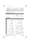
DIMENSIONS
reducer/expander pipe
OF THE PIPING
Branch dimensions
CZ-P20BK12Q
CZ-P20BK12QA
liquid branch
Ø12.70
Ø9.52
discharge gas branch
CZ-P29BK12Q
Ø19.10
Ø15.90
Ø12.70
—
Ø6.35
Ø9.52
Ø12.70
Ø9.52
Ø12.70
Ø15.90
Ø19.10
—
12Q reducer or expander pipe 1, 3
12QA reducer or expander pipe 12, 2x1, 3
Ø25.40
Ø22.20
Ø19.10
Ø9.52
Ø6.35
Ø19.10
Ø15.90
Ø12.70
—
Ø6.35
Ø9.52
reducer or expander pipe 11
CZ-P64BK12Q
Ø15.90
Ø19.10
Ø22.20
Ø9.52
Ø6.35
—
Ø12.70
Ø15.90
Ø9.52
Ø12.70
Ø15.90
—
reducer or expander pipe 6, 2x 7
Ø31.80
Ø28.60
Ø25.40
Ø15.90
Ø12.70
Ø9.52
Ø25.40
Ø19.10
Ø15.90
—
Ø6.35
Ø9.52
Ø12.70
reducer or expander pipe 2x 4
CZ-P20~75BK12+32Q(A)
Branches
4PW15565-1D
suction gas branch
Ø12.70
Ø15.90
Ø19.10
—
reducer or expander pipe 6, 5, 7, 8
Installation manual
1
liquid branch
CZ-P75BK12Q
Ø15.90
Ø19.10
Ø22.20
discharge gas branch
suction gas branch
Ø19.10
Ø15.90
Ø12.70
Ø31.80
Ø28.60
Ø25.40
Ø38.10
Ø31.80
—
Ø12.70
Ø15.90
Ø19.10
Ø15.90
Ø19.10
Ø25.40
CZ-P20BK32Q
reducer or expander pipe 2
Ø12.70
Ø9.52
—
reducer or expander pipe 3, 5, 8, 2x 9, 10
CZ-P29BK32Q
—
reducer or expander pipe 1, 3
Ø12.70
Ø15.90
Ø19.10
Ø19.10
Ø15.90
Ø12.70
Ø6.35
Ø9.52
CZ-P64BK32Q
Ø19.10
Ø15.90
Ø12.70
Ø9.52
Ø12.70
Ø15.90
—
reducer or expander pipe 6, 2x 7
Ø25.40
Ø22.20
Ø19.10
Ø15.90
Ø12.70
Ø9.52
Ø31.80
Ø28.60
Ø25.40
Ø19.10
Ø15.90
Ø12.70
Ø6.35
Ø9.52
Ø12.70
Ø25.40
Ø19.10
Ø15.90
Ø9.52
Ø12.70
Ø15.90
reducer or expander pipe 2x 4
CZ-P75BK32Q
Ø25.40
Ø22.20
Ø19.10
Ø9.52
Ø12.70
Ø15.90
reducer or expander pipe 11
Ø15.90
Ø19.10
Ø22.20
Ø12.70
Ø15.90
Ø19.10
—
Ø9.52
Ø6.35
Ø12.70
Ø15.90
Ø19.10
Ø15.90
Ø12.70
Ø6.35
Ø9.52
Ø12.70
Ø6.35
Ø9.52
Ø12.70
Ø9.52
Ø15.90
Ø19.10
Ø22.20
Ø15.90
Ø12.70
Ø9.52
Ø12.70
Ø15.90
Ø9.52
Ø6.35
Ø12.70
Ø15.90
Ø19.10
reducer or expander pipe 4, 6, 2x 7
Ø19.10
Ø15.90
Ø12.70
Ø31.80
Ø28.60
Ø25.40
reducer or expander pipe 5, 8
Ø25.40
Ø19.10
Ø15.90
Ø12.70
Ø15.90
Ø19.10
Ø31.80
Ø28.60
Ø25.40
Ø38.10
Ø31.80
Ø12.70
Ø15.90
Ø19.10
reducer or expander pipe 2
Ø15.90
Ø19.10
Ø25.40
reducer or expander pipe 1, 5, 6, 7, 8, 9
reducer or expander pipe 3, 5, 8, 2x 9, 10
Reducer/expander pipe dimensions
1
2
OD Ø12.70
ID Ø9.52
4
3
OD Ø12.70
7
ID Ø28.60
OD Ø31.80
ID Ø38.10
10
ID Ø22.20
ID Ø25.40
9
OD Ø25.40
ID Ø28.60
11
OD Ø31.80
ID Ø31.80
ID Ø34.95
ID Ø41.28
12
OD Ø9.52
Installation manual
OD Ø19.10
ID Ø22.20
8
OD Ø25.40
ID Ø12.70
6
OD Ø19.10
ID Ø19.10
OD Ø15.90
ID Ø6.35
5
OD Ø15.90
2
ID Ø9.52
ID Ø12.7
OD Ø9.52
ID Ø6.35
CZ-P20~75BK12+32Q(A)
Branches
4PW15565-1D
INSTALLATION
INSTALLATION
PROCEDURE
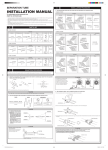
Use a pipe cutter to cut off the pipe at a position where the size of the
pipe fits the size of the connecting pipe selected according to the
pipe selection procedure.
pipe cutter (cut the center area of the piping)
field pipe
PRECAUTIONS
Make sure to flow nitrogen gas through the pipe when
brazing.
Installation orientation
Install the branches so that they are oriented vertically or horizontally.
horizontal viewpoint
Use the supplied reducer/expander pipes when necessary
pipe cutter
(cut the center area of the piping)
Within 30°
expander pipe (supplied)
(horizontal line)
horizontal
or vertical
Heat insulation
Be sure to insulate the branches against heat.
■
Example of connected branch.
field pipe
field pipe
■
branch (supplied)
field pipe
Use the supplied heat insulation material to insulate the
branches against heat.
heat insulation material
(supplied)
■
Apply the heat insulation material and seal all connections with
tape.
field piping
heat insulation material
CZ-P20~75BK12+32Q(A)
Branches
4PW15565-1D
tape
Installation manual
3
NOTES
Matsushita Electric Industrial Co., Ltd., Osaka, Japan
Made in Belgium
CZ-P20~75BK12+32Q(A)
4PW15565-1D