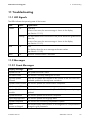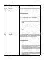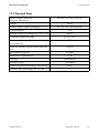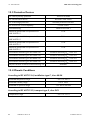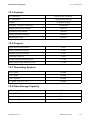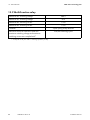
1
Wind Power Inverters
WINDY BOY 3000TL / 3600TL / 4000TL / 5000TL
Installation Manual
WB3-5TL-21-IA-en-10 | IMEN-WB3-5TL-21 | Version 1.0
EN
SMA Solar Technology AG
Table of Contents
Table of Contents
1 Information about this document . . . . . . . . . . . . . . . . . . . . . . . . 7
2 Safety . . . . . . . . . . . . . . . . . . . . . . . . . . . . . . . . . . . . . . . . . . . . . 10
2.1 Intended Use . . . . . . . . . . . . . . . . . . . . . . . . . . . . . . . . . . . . . . . . . . . 10
2.2 Skills of Qualified Persons . . . . . . . . . . . . . . . . . . . . . . . . . . . . . . . . . 11
2.3 Safety Precautions . . . . . . . . . . . . . . . . . . . . . . . . . . . . . . . . . . . . . . . 11
3 Scope of Delivery . . . . . . . . . . . . . . . . . . . . . . . . . . . . . . . . . . . . 12
4 Product Description . . . . . . . . . . . . . . . . . . . . . . . . . . . . . . . . . . 13
4.1
4.2
4.3
4.4
4.5
4.6
4.7
4.8
4.9
4.10
Windy Boy. . . . . . . . . . . . . . . . . . . . . . . . . . . . . . . . . . . . . . . . . . . . .
Type Label . . . . . . . . . . . . . . . . . . . . . . . . . . . . . . . . . . . . . . . . . . . . .
Display. . . . . . . . . . . . . . . . . . . . . . . . . . . . . . . . . . . . . . . . . . . . . . . .
Bluetooth. . . . . . . . . . . . . . . . . . . . . . . . . . . . . . . . . . . . . . . . . . . . .
Slot for Communication Interface . . . . . . . . . . . . . . . . . . . . . . . . . . .
Operating Parameters . . . . . . . . . . . . . . . . . . . . . . . . . . . . . . . . . . . .
Slot for Multi-Function Interface . . . . . . . . . . . . . . . . . . . . . . . . . . . . .
Grid Management. . . . . . . . . . . . . . . . . . . . . . . . . . . . . . . . . . . . . . .
Varistors . . . . . . . . . . . . . . . . . . . . . . . . . . . . . . . . . . . . . . . . . . . . . . .
SMA Grid Guard . . . . . . . . . . . . . . . . . . . . . . . . . . . . . . . . . . . . . . .
13
15
17
20
20
20
21
21
21
22
5 Mounting. . . . . . . . . . . . . . . . . . . . . . . . . . . . . . . . . . . . . . . . . . . 23
5.1 Selecting the Mounting Location . . . . . . . . . . . . . . . . . . . . . . . . . . . . 23
5.2 Mounting the Inverter . . . . . . . . . . . . . . . . . . . . . . . . . . . . . . . . . . . . 26
6 Electrical Connection . . . . . . . . . . . . . . . . . . . . . . . . . . . . . . . . . 28
6.1 Safety during Electrical Connection. . . . . . . . . . . . . . . . . . . . . . . . . . 28
6.2 Overview of the Connection Area . . . . . . . . . . . . . . . . . . . . . . . . . . . 28
6.2.1 View from Below . . . . . . . . . . . . . . . . . . . . . . . . . . . . . . . . . . . . . . . 28
6.2.2 Interior View. . . . . . . . . . . . . . . . . . . . . . . . . . . . . . . . . . . . . . . . . . . 29
Installation Manual
WB3-5TL-21-IA-en-10
3
Table of Contents
SMA Solar Technology AG
6.3 AC Connection . . . . . . . . . . . . . . . . . . . . . . . . . . . . . . . . . . . . . . . . . 29
6.3.1 Conditions for the AC Connection . . . . . . . . . . . . . . . . . . . . . . . . . . 29
6.3.2 Connecting the Inverter to the Power Distribution Grid . . . . . . . . . . 31
6.3.3 Additional Grounding of the Enclosure . . . . . . . . . . . . . . . . . . . . . . 34
6.4 DC Connection . . . . . . . . . . . . . . . . . . . . . . . . . . . . . . . . . . . . . . . . . 35
6.4.1 Connecting the Connection Cables to DC Connectors . . . . . . . . . . 35
6.4.2 Bridging the DC Inputs on the Inverter . . . . . . . . . . . . . . . . . . . . . . . 37
6.4.3 Connecting the Rectifier . . . . . . . . . . . . . . . . . . . . . . . . . . . . . . . . . . 38
7 Initial Start-Up. . . . . . . . . . . . . . . . . . . . . . . . . . . . . . . . . . . . . . . 42
7.1
7.2
7.3
7.4
7.5
Procedure . . . . . . . . . . . . . . . . . . . . . . . . . . . . . . . . . . . . . . . . . . . . .
Configuring the Country Data Set . . . . . . . . . . . . . . . . . . . . . . . . . . .
Setting the NetID . . . . . . . . . . . . . . . . . . . . . . . . . . . . . . . . . . . . . . . .
Commissioning the Inverter for the First Time . . . . . . . . . . . . . . . . . . .
For Italy Only: Starting the Self-Test. . . . . . . . . . . . . . . . . . . . . . . . . .
42
42
45
46
47
7.5.1 Abortion of the Self-Test . . . . . . . . . . . . . . . . . . . . . . . . . . . . . . . . . . 48
7.5.2 Restarting the Self-Test . . . . . . . . . . . . . . . . . . . . . . . . . . . . . . . . . . . 48
8 Configuration . . . . . . . . . . . . . . . . . . . . . . . . . . . . . . . . . . . . . . . 49
8.1
8.2
8.3
8.4
8.5
Changing the Display Language . . . . . . . . . . . . . . . . . . . . . . . . . . . .
Changing the Plant Password and Plant Time . . . . . . . . . . . . . . . . . .
Adapting the Polynomial Curve . . . . . . . . . . . . . . . . . . . . . . . . . . . . .
Setting the Deactivation Delay . . . . . . . . . . . . . . . . . . . . . . . . . . . . .
Changing the DC Critical Voltage for Feed-in to the
Power Distribution Grid . . . . . . . . . . . . . . . . . . . . . . . . . . . . . . . . . . .
8.6 Connecting the Inverter to Sunny Portal. . . . . . . . . . . . . . . . . . . . . . .
8.7 Setting the Operating Parameters . . . . . . . . . . . . . . . . . . . . . . . . . . .
49
50
50
51
52
53
53
9 Disconnecting the Inverter from Voltage Sources . . . . . . . . . . 54
10 Recommissioning the Inverter . . . . . . . . . . . . . . . . . . . . . . . . . . 57
4
WB3-5TL-21-IA-en-10
Installation Manual
SMA Solar Technology AG
Table of Contents
11 Troubleshooting . . . . . . . . . . . . . . . . . . . . . . . . . . . . . . . . . . . . . 59
11.1 LED Signals . . . . . . . . . . . . . . . . . . . . . . . . . . . . . . . . . . . . . . . . . . . . 59
11.2 Messages . . . . . . . . . . . . . . . . . . . . . . . . . . . . . . . . . . . . . . . . . . . . . 59
11.2.1 Event Messages . . . . . . . . . . . . . . . . . . . . . . . . . . . . . . . . . . . . . . . . 59
11.2.2 Error Messages . . . . . . . . . . . . . . . . . . . . . . . . . . . . . . . . . . . . . . . . 60
11.3
11.4
11.5
11.6
Cleaning the Inverter . . . . . . . . . . . . . . . . . . . . . . . . . . . . . . . . . . . . .
Checking the Small Wind Turbine System for Ground Faults . . . . . .
Checking the Function of the Varistors. . . . . . . . . . . . . . . . . . . . . . . .
Replacing the Varistors . . . . . . . . . . . . . . . . . . . . . . . . . . . . . . . . . . .
70
71
72
73
12 Decommissioning . . . . . . . . . . . . . . . . . . . . . . . . . . . . . . . . . . . . 75
12.1 Disassembling the Inverter . . . . . . . . . . . . . . . . . . . . . . . . . . . . . . . . . 75
12.2 Packing the Inverter . . . . . . . . . . . . . . . . . . . . . . . . . . . . . . . . . . . . . . 76
12.3 Disposing of the Inverter . . . . . . . . . . . . . . . . . . . . . . . . . . . . . . . . . . 76
13 Technical Data . . . . . . . . . . . . . . . . . . . . . . . . . . . . . . . . . . . . . . 77
13.1 DC/AC . . . . . . . . . . . . . . . . . . . . . . . . . . . . . . . . . . . . . . . . . . . . . . . 77
13.1.1 Windy Boy 3000TL . . . . . . . . . . . . . . . . . . . . . . . . . . . . . . . . . . . . . 77
13.1.2 Windy Boy 3600TL . . . . . . . . . . . . . . . . . . . . . . . . . . . . . . . . . . . . . 79
13.1.3 Windy Boy 4000TL . . . . . . . . . . . . . . . . . . . . . . . . . . . . . . . . . . . . . 81
13.1.4 Windy Boy 5000TL . . . . . . . . . . . . . . . . . . . . . . . . . . . . . . . . . . . . . 83
13.2
13.3
13.4
13.5
13.6
13.7
13.8
13.9
General Data. . . . . . . . . . . . . . . . . . . . . . . . . . . . . . . . . . . . . . . . . . .
Protective Devices . . . . . . . . . . . . . . . . . . . . . . . . . . . . . . . . . . . . . . .
Climatic Conditions . . . . . . . . . . . . . . . . . . . . . . . . . . . . . . . . . . . . . .
Features . . . . . . . . . . . . . . . . . . . . . . . . . . . . . . . . . . . . . . . . . . . . . . .
Torques . . . . . . . . . . . . . . . . . . . . . . . . . . . . . . . . . . . . . . . . . . . . . . .
Grounding Systems . . . . . . . . . . . . . . . . . . . . . . . . . . . . . . . . . . . . . .
Data Storage Capacity . . . . . . . . . . . . . . . . . . . . . . . . . . . . . . . . . . .
Multi-Function relay . . . . . . . . . . . . . . . . . . . . . . . . . . . . . . . . . . . . . .
85
86
86
87
87
87
87
88
14 Accessories . . . . . . . . . . . . . . . . . . . . . . . . . . . . . . . . . . . . . . . . . 89
15 Contact . . . . . . . . . . . . . . . . . . . . . . . . . . . . . . . . . . . . . . . . . . . . 90
Installation Manual
WB3-5TL-21-IA-en-10
5
Table of Contents
6
WB3-5TL-21-IA-en-10
SMA Solar Technology AG
Installation Manual
SMA Solar Technology AG
1 Information about this document
1 Information about this document
Validity
This document is valid for the following device types as of firmware version 2.10:
• WB 3000TL-21
• WB 3600TL-21
• WB 4000TL-21
• WB 5000TL-21
Target Group
This document is intended for qualified persons. Only qualified personnel with the appropriate skills
are allowed to perform the tasks described in this document (see Section 2.2 "Skills of Qualified
Persons", page 11).
Additional Information
Links to additional information can be found at www.SMA-Solar.com:
Document title
Document type
Miniature Circuit-Breaker
Technical information
Measured Values and Parameters
® Wireless Technology
Technical description
SMA Bluetooth ‒ SMA Bluetooth
in Practice
Technical information
SMA Bluetooth® Wireless Technology
Technical description
Installation Manual
WB3-5TL-21-IA-en-10
7
1 Information about this document
SMA Solar Technology AG
Symbols
Symbol
Explanation
Indicates a hazardous situation which, if not avoided, will result in death
or serious injury
Indicates a hazardous situation which, if not avoided, can result in death
or serious injury
Indicates a hazardous situation which, if not avoided, can result in minor
or moderate injury
Indicates a situation which, if not avoided, could result in property damage
Information that is important for a specific topic or goal, but is not
safety-relevant
☐
Indicates an essential requirement for achieving a specific goal
☑
Desired result
✖
A problem that could occur
Typographies
Typography
bold
Use
• Display messages
• Parameters
• Connections
• Elements on an interface
text
Example
• Select the Set country
standard parameter and
adjust the required
country data set.
• Elements to be selected
• Elements to be entered
[Button]
8
• Button on a user interface
WB3-5TL-21-IA-en-10
• Select
[Device selection].
Installation Manual
SMA Solar Technology AG
1 Information about this document
Nomenclature
Complete designation
Designation in this document
Torque
Torque
Electronic Solar Switch
ESS
Small wind turbine system
Small wind turbine system, plant
SMA Bluetooth® Wireless Technology
Bluetooth
Windy Boy
Inverter, product
Abbreviations
Abbreviations
Designation
Explanation
AC
Alternating Current
‒
DC
Direct Current
‒
EC
European Community
‒
EMC
Electromagnetic Compatibility
‒
LED
Light-Emitting Diode
‒
MSL
Mean Sea Level
‒
NetID
Network Identification
Identification number for
SMA Bluetooth network
PC
Personal Computer
‒
PE
Protective Earth
Protective conductor
SWTS
Small Wind Turbine System
‒
VDE
Verband der Elektrotechnik Elektronik
Informationstechnik e.V.
Association for Electrical, Electronic
and Information Technologies
Installation Manual
WB3-5TL-21-IA-en-10
9
2 Safety
SMA Solar Technology AG
2 Safety
2.1 Intended Use
The Windy Boy is a transformerless wind power inverter that converts the rectified alternating current
of a small wind turbine system or other energy converters based on permanent magnet electric
generators into alternating current suitable for the grid and feeds this energy into the power
distribution grid or stand-alone grid.
Load resistor
Small Wind
Turbine System
Figure 1:
Windy Boy Protection Box
Windy Boy
power
distribution grid
Principle of a small wind turbine system with Windy Boy
The Windy Boy is suitable for indoor and outdoor use.
The Windy Boy may only be used with small wind turbine systems or with energy converters based
on permanent magnet electric generators (e.g. water energy plants, CHP plants, diesel generators).
The small wind turbine system or energy converter must be suitable for use with the Windy Boy and
approved by the small wind turbine system or energy converter manufacturer. SMA Solar Technology
recommends operating Windy Boy together with a small wind turbine system without neutral
grounding.
The Windy Boy must not be connected to a direct current supply grid.
An overvoltage protection must be installed between the Windy Boy and the rectifier to limit the direct
voltage. Use only an overvoltage protection that is designed for the maximum power of the small wind
turbine system. SMA Solar Technology recommends using the Windy Boy Protection Box of type
500-11. If you are not using the Windy Boy Protection Box of type 500-11, you must install a capacity
of at least 120 μF between the Windy Boy and the rectifier. A low DC voltage ripple has a positive
effect on the electrical endurance of the inverter.
All components must remain within their permitted operating ranges at all times.
Alternative uses of the Windy Boy not expressly recommended by SMA Solar Technology AG are
not permitted.
The Windy Boy must not be connected in parallel with other inverters on the DC side.
10
WB3-5TL-21-IA-en-10
Installation Manual
SMA Solar Technology AG
2 Safety
For safety reasons, it is not permitted to modify the product or install components that are not explicitly
recommended or distributed by SMA Solar Technology AG for this product.
Before carrying out work on the inverter and before the ESS can be removed, the small wind turbine
system must always be stopped and secured against restart. Disconnecting the inverter and removing
the ESS while the small wind turbine system is running can cause damage to the small wind turbine
system and the inverter due to the resulting rapid discharge.
• Do not mount the Windy Boy on flammable construction materials.
• Do not mount the Windy Boy near areas containing highly flammable materials.
• Do not mount the Windy Boy in potentially explosive areas.
The enclosed documentation is an integral part of this product.
• Read and observe the documentation.
• Keep the documentation in a convenient place for future reference.
2.2 Skills of Qualified Persons
The tasks described in this document must be performed by qualified persons only. Qualified persons
must have the following skills:
• Knowledge of how an inverter works and is operated
• Training in how to deal with the dangers and risks associated with installing and using electrical
devices and plants
• Training in the installation and commissioning of electrical devices and plants
• Knowledge of all applicable standards and directives
• Knowledge of and adherence to this document and all safety precautions
2.3 Safety Precautions
Electric Shock
High voltages that can cause fatal electric shocks when touched are present in the live components
of the inverter.
• Prior to performing any work on the inverter, disconnect it from any voltage source as described
in this document (see Section 9).
Burn Hazards
Some parts of the enclosure can become hot during operation.
• Do not touch any parts other than the lower enclosure lid of the inverter during operation.
Electrostatic Discharge
By touching electronic components, you can damage or even destroy the inverter through electrostatic
discharge (ESD).
• Ground yourself before touching any components.
Installation Manual
WB3-5TL-21-IA-en-10
11
3 Scope of Delivery
SMA Solar Technology AG
3 Scope of Delivery
Check the scope of delivery for completeness and any externally visible damage. Contact your
specialty retailer if the scope of delivery is incomplete or damaged.
Figure 2:
Components included in the scope of delivery
Position
Quantity
Description
A
1
Inverter
B
1
Wall mounting bracket
C
4
Positive DC connector
D
4
Negative DC connector
E
8
Sealing plug
F
1
Installation manual, user manual, document set with explanations
and certificates, supplementary sheet with the default settings
12
WB3-5TL-21-IA-en-10
Installation Manual
SMA Solar Technology AG
4 Product Description
4 Product Description
4.1 Windy Boy
The Windy Boy is a transformerless wind power inverter that converts the alternating current of a small
wind turbine system into alternating current suitable for the grid and feeds this energy into the power
distribution grid or stand-alone grid.
A
B
G
F
C
E
D
Figure 3:
Design of the Windy Boy
Position
Description
A
Cooling fins
B
Type label
C
LEDs
D
Display
E
Electronic Solar Switch (ESS)
F
Lower enclosure lid
G
Upper enclosure lid
Installation Manual
WB3-5TL-21-IA-en-10
13
4 Product Description
SMA Solar Technology AG
Symbols on the inverter
Symbol
14
Description
Explanation
Inverter
This symbol defines the function of the
green LED. The green LED indicates the
operating state of the inverter.
Observe documentation
This symbol defines the function of the
red LED. The red LED indicates an error.
Read this document to remedy the error.
Bluetooth
This symbol defines the function of the
blue LED. The blue LED indicates that the
Bluetooth communication is enabled.
QR Code®
The QR Code® refers to the SMA bonus
program (for information on this, see
www.SMA-Bonus.com).
Danger
If a second protective conductor is
required, also ground the enclosure (see
Section 6.3.3).
Danger to life due to high
voltages in the inverter; observe
waiting time.
High voltages that can cause fatal
electric shocks are present in the live
components of the inverter. Disconnect
the inverter from any voltage sources
before performing any work on it
(see Section 9).
WB3-5TL-21-IA-en-10
Installation Manual
SMA Solar Technology AG
4 Product Description
4.2 Type Label
The type label provides a unique identification of the inverter. The type label is on the right-hand side
of the enclosure.
Figure 4:
Layout of the type label
Position
Description
Explanation
A
Model
Inverter device type
B
Date of manufacture
Inverter manufacture date
(year-month-day)
C
Additional information
Field for additional information, e.g.
standard information
D
Device-specific characteristics
‒
E
Serial No.
Inverter serial number
You will require the information on the type label to use the inverter safely and when seeking customer
support from the SMA Service Line. The type label must be permanently affixed to the inverter.
Installation Manual
WB3-5TL-21-IA-en-10
15
4 Product Description
SMA Solar Technology AG
Symbols on the type label
Symbol
16
Description
Explanation
Danger to life due to high
voltages.
The product operates at high voltages.
All work on the inverter must be carried out by
qualified persons only.
Risk of burns from hot
surfaces
The product can become hot during operation.
Avoid contact during operation. Allow the
product to cool down sufficiently before
carrying out any work. Wear personal
protective equipment such as safety gloves.
Observe documentation
Observe all documentation that is supplied
with the product.
DC
Direct current
Without transformer
The product does not have a transformer.
AC
Alternating current
WEEE designation
Do not dispose of the product together with the
household waste but in accordance with the
locally applicable disposal regulations for
electronic waste.
CE marking
The product complies with the requirements of
the applicable EC directives.
Device class ID
The product is equipped with a wireless
component and complies with device class 2.
Degree of protection
The product is protected against dust intrusion
and water jets from any angle.
Outdoor
The product is suitable for outdoor installation.
RAL quality mark for solar
products
The product complies with the requirements of
the German Institute for Quality Assurance
and Certification.
WB3-5TL-21-IA-en-10
Installation Manual
SMA Solar Technology AG
Symbol
4 Product Description
Description
Explanation
Certified safety
The product is VDE-tested and complies with
the requirements of the German Equipment
and Product Safety Act.
C-Tick
The product complies with the requirements of
the applicable Australian EMC standards.
4.3 Display
The display shows the current operating data of the inverter (e.g. current power, daily energy, total
energy) as well as events or errors. The power and energy are displayed as bars in the diagram.
There is a slot for an SD card on the left edge of the display enclosure. You can use the SD card to
carry out an inverter firmware update, for example (for information on firmware updates with an
SD card see the technical description "Firmware Update with SD Card" at www.SMA-Solar.com).
Figure 5:
Display layout (example)
Position
Description
Explanation
A
Power
Current power
B
Day
Daily energy
C
Total
Displays the total amount of energy fed in up until now
D
Active functions
The different symbols indicate which functions for
communication, grid management or temperature
derating are enabled or active.
Installation Manual
WB3-5TL-21-IA-en-10
17
4 Product Description
SMA Solar Technology AG
Position
Description
Explanation
E
Line conductor
Indicates which line conductor the displayed values are
assigned to.
F
Event number relating to the Event number of errors relating to the power distribution
power distribution grid
grid
G
Output voltage/
output current
H
Event number relating to the Event number of errors relating to the inverter
inverter
I
Input voltage/
input current
K
Event number relating to the Event number of errors relating to the small wind turbine
small wind turbine system system
L
Text line
Displays the event message or error message
M
Power and yield curve
Changes in power over the last 16 feed-in hours or the
energy yields over the last 16 days
Displays output voltage and output current of a line
conductor in alternation
Displays input voltage and input current of one input in
alternation
• In order to switch between the displays, tap once
on the enclosure lid
Symbols on the display
Symbol
Description
Explanation
Tapping
You can operate the display by tapping on the
enclosure lid:
• Tapping once: to activate the backlight,
to scroll to the next text line, to switch
between the power graphs of the last
16 feed-in hours and the energy yields of
the last 16 days.
• Tapping twice: the display shows, in
succession, the firmware version, the
serial number or designation of the
inverter, NetID, the configured country
data set and display language.
Telephone receiver
Indicates that an error cannot be rectified on
site
• Contact the SMA Service Line.
18
WB3-5TL-21-IA-en-10
Installation Manual
SMA Solar Technology AG
Symbol
4 Product Description
Description
Explanation
Wrench
Indicates that an error can be rectified on site
Bluetooth
Indicates that an active Bluetooth connection is
established
Bluetooth connection
quality
Indicates the quality of the Bluetooth
connection to other Bluetooth devices
Speedwire
If a Speedwire data module is installed in the
inverter, this symbol indicates that there is a
connection to a network.
Webconnect function
If a Webconnect data module is installed in the
inverter, this symbol indicates that it is possible
to connect to the Sunny Portal.
Multi-function relay
Indicates that the multi-function relay is active
Thermometer
Indicates that the power of the inverter is
limited due to excessive temperature
Power limitation
Indicates that the external active power
limitation via the plant control is active
Small wind turbine system
with rectifier
‒
Inverter
‒
Grid relay
A closed grid relay indicates that the inverter is
feeding into the power distribution grid.
An open grid relay shows that the inverter is
disconnected from the power distribution grid.
Power distribution grid
Installation Manual
‒
WB3-5TL-21-IA-en-10
19
4 Product Description
SMA Solar Technology AG
4.4 Bluetooth
The inverter is equipped as standard with a Bluetooth interface and can communicate with special
SMA communication products or other inverters (for information on supported products, see
www.SMA-Solar.com).
If you would like to communicate via Bluetooth, you can protect the inverter with one plant password
for the user and one plant password for the installer.
All inverters are delivered with a standard plant password for the user (0000) and a standard plant
password for the installer (1111). To protect the plant from unauthorized access, you must change
the plant passwords using Sunny Explorer (for information on changing the plant password, refer to
the Sunny Explorer help).
If you do not wish to communicate via Bluetooth, deactivate the Bluetooth communication
(see Section 7.3 "Setting the NetID", page 45).
4.5 Slot for Communication Interface
The inverter can optionally be fitted with an extra communication interface (e.g. RS485).
This communication interface enables the inverter to communicate with special SMA communication
products (for information on supported products, see www.SMA-Solar.com). The communication
interface can be retrofitted or installed by default with the respective order.
Depending on the type of communication, RS485, Bluetooth, or Speedwire, the parameters and
messages are displayed differently on the communication products.
Example: How the country data set parameter is displayed
• For communication with RS485: CntrySet parameter
• For communication with Bluetooth or Speedwire: Set country standard parameter
4.6 Operating Parameters
Various operating parameters control the functionality of the inverter. You can only adjust all
operating parameters of the inverter, excluding the country data set, using an SMA communication
product (see Section 8.7). You can adjust the country data set before commissioning or within the first
ten feed-in hours via two rotary switches in the inverter (see Section 7.2).
20
WB3-5TL-21-IA-en-10
Installation Manual
SMA Solar Technology AG
4 Product Description
4.7 Slot for Multi-Function Interface
The inverter has a slot for a multi-function interface. This slot is designed to connect a simple
multi-function relay, an SMA Power Control Module, or a fan retrofit kit. The multi-function interface
can be retrofitted or installed by default with the respective order.
Multi-Function Relay
You can configure the multi-function relay for various operating modes. The multi-function relay is
used, for example, to switch error indicators on or off (for information on installation and
configuration, see installation manual of the multi-function relay).
SMA Power Control Module
The SMA Power Control Module enables the inverter to implement grid management and is equipped
with an additional multi-function relay (for information on installation and configuration, see the
SMA Power Control Module installation manual).
Fan Retrofit Kit
The fan retrofit kit is used for additional inverter cooling at high ambient temperatures and also has a
multi-function relay (for information on installation and configuration, see the fan retrofit kit installation
manual). The fan retrofit kit and the SMA Power Control Module cannot be operated in parallel.
4.8 Grid Management
The inverter is equipped with grid management functions.
Depending on the requirements of the grid operator, you can activate and configure the functions
(e.g. provision of reactive power, active power limitation) via operating parameters (for information
on the functions and operating parameters, see the Technical Description "Measured Values and
Parameters" at www.SMA-Solar.com).
4.9 Varistors
Varistors are voltage-dependent resistors that protect the inverters against overvoltage. The inverter is
equipped with thermally monitored varistors.
Varistors can become worn and lose their protective function with age or repeated strain as a result
of overvoltage. The inverter detects if one of the varistors is defective and displays an error message.
The varistors are specially manufactured for use in the inverter and are not commercially available.
You must order new varistors directly from SMA Solar Technology AG.
Installation Manual
WB3-5TL-21-IA-en-10
21
4 Product Description
SMA Solar Technology AG
4.10 SMA Grid Guard
SMA Grid Guard acts as an automatic disconnection device between a grid-parallel generator
(e.g. a PV plant or small wind turbine system) and the power distribution grid.
Furthermore, SMA Grid Guard is a grid monitoring concept which detects errors by permanently
monitoring grid impedance, line voltage and power frequency. For example, SMA Grid Guard
detects when a stand-alone grid is formed and immediately disconnects the inverter from the power
distribution grid.
In some countries, the connection conditions require a device which protects grid-relevant operating
parameters against unpermitted changes. SMA Grid Guard assumes this function and protects the
setting of the country data set after the first 10 feed-in hours. After the first 10 feed-in hours the country
data set can only be changed using a communication product and after a personal access code has
been entered, the SMA Grid Guard code. You can obtain the SMA Grid Guard code from
SMA Solar Technology AG (for application for the SMA Grid Guard code, see certificate
"Application for SMA Grid Guard-Code" at www.SMA-Solar.com).
22
WB3-5TL-21-IA-en-10
Installation Manual
SMA Solar Technology AG
5 Mounting
5 Mounting
5.1 Selecting the Mounting Location
Requirements for the mounting location:
Danger to life due to fire or explosion
Despite careful construction, electrical devices can cause fires.
• Do not mount the inverter on flammable construction materials.
• Do not mount the inverter in areas where highly flammable materials are stored.
• Do not mount the inverter in a potentially explosive atmosphere.
☐ The mounting location must be inaccessible to children.
☐ A solid foundation must be available for mounting, e.g. concrete or masonry. When mounted
on plasterboard or similar materials in a living area, the inverter will develop audible vibrations
during operation, which could be considered disturbing.
☐ The mounting location must be suitable for the weight and dimensions of the inverter
(see Section 13 "Technical Data", page 77).
☐ The mounting location must be easily and safely accessible at all times without the use of
additional aids being necessary, e.g., scaffolding or lifting platforms. Non-fulfillment of these
criteria may restrict servicing.
☐ The mounting location must not be exposed to direct solar irradiation. Direct solar irradiation
can overheat the inverter. As a result, the inverter reduces its power output.
☐ Climatic conditions must be met (see Section 13 "Technical Data", page 77).
☐ The ambient temperature must be below 40°C to ensure the optimal operation of the inverter.
Installation Manual
WB3-5TL-21-IA-en-10
23
5 Mounting
SMA Solar Technology AG
Dimensions for wall mounting:
Figure 6:
24
Wall mounting bracket dimensioning
WB3-5TL-21-IA-en-10
Installation Manual
SMA Solar Technology AG
5 Mounting
Observe recommended clearances:
Figure 7:
Recommended clearances
• Observe minimum clearances to the walls as well as to other inverters or objects.
This ensures adequate heat dissipation and sufficient space to remove the ESS.
• If multiple inverters are mounted in areas with high ambient temperatures, increase the
clearances between the inverters and ensure sufficient fresh-air supply.
☑ This prevents a reduction in inverter power as a result of high temperatures (for details
on temperature derating, see the Technical Information "Temperature Derating"
at www.SMA-Solar.com).
Observe permitted mounting position:
Figure 8:
Permitted and prohibited mounting positions
Installation Manual
WB3-5TL-21-IA-en-10
25
5 Mounting
SMA Solar Technology AG
• Mount the inverter in a permitted mounting position. The display should be mounted at eye level.
☑ Mounting the inverter in a permissible position will ensure that no moisture can penetrate the
inverter.
☑ By mounting the device at eye level, display messages and LED signals can be read without
difficulty.
5.2 Mounting the Inverter
Anti-theft device:
You can protect the inverter from theft with a padlock. The padlock locks the inverter to the wall
mounting bracket.
The device must meet the following requirements:
☐ The material must be resistant to corrosion.
☐ The lock shackle must be hardened.
☐ The lock cylinder must be secured.
☐ If it is mounted outdoors, the padlock must be weather-proof.
☐ The function must be guaranteed for the electrical endurance of the inverter.
Figure 9:
Dimensions of the padlock for the anti-theft device
Additionally required mounting material (not included in the scope of delivery):
☐ 3 screws (minimum diameter 6 mm) that are suitable for the foundation
☐ 3 washers (minimum external diameter 18 mm) that are suitable for the screws
☐ 3 screw anchors that are suitable for the foundation
☐ If the inverter is to be protected against theft, 1 padlock
1. Ensure that there are no lines laid in the wall which could be damaged when drilling.
26
WB3-5TL-21-IA-en-10
Installation Manual
SMA Solar Technology AG
5 Mounting
2. Mark the position of the drill holes using the wall mounting bracket. Use at least two holes on
the left-hand and right-hand side and the lower hole in the wall mounting bracket.
Tip: When mounting on a post, use the upper and lower central holes.
3. Drill the holes and insert the screw anchors.
4. Secure the wall mounting bracket horizontally to
the wall using screws and washers.
5.
Risk of injury when hanging the inverter in the wall mounting bracket
• Keep in mind the weight of the inverter (see Section 13 "Technical Data", page 77).
• Hang the inverter in the wall mounting
bracket. Use the recessed grips at the side
and transport the inverter in a horizontal
position.
6. Ensure that the inverter is securely seated.
7. To protect the inverter from theft, attach a padlock:
• Place the shackle of the padlock through the
metal lug on the wall mounting bracket and
through the lug on the rear of the inverter.
As you do so, move the shackle outward from
the center of the inverter.
• Close the shackle.
Installation Manual
WB3-5TL-21-IA-en-10
27
6 Electrical Connection
SMA Solar Technology AG
6 Electrical Connection
6.1 Safety during Electrical Connection
Electric Shock
High voltages that can cause fatal electric shocks when touched are present in the live components
of the inverter.
• Prior to performing any work on the inverter, disconnect it from any voltage source as described
in this document (see Section 9).
Electrostatic Discharge
Touching electronic components can cause damage to or destroy the inverter through electrostatic
discharge.
• Ground yourself before touching any components.
6.2 Overview of the Connection Area
6.2.1 View from Below
A
B
C
D
Figure 10: Enclosure openings at the bottom of the inverter
Position
Description
A
Cable gland M20x1.5 for connection to the multi-function interface or connection
of the fan retrofit kit
B
Enclosure opening with filler-plug for connection to the communication interface
C
Enclosure opening with filler-plug for connection to the communication interface
D
Cable gland M32x1.5 for connection to the power distribution grid
28
WB3-5TL-21-IA-en-10
Installation Manual
SMA Solar Technology AG
6 Electrical Connection
6.2.2 Interior View
B
A
H
C
D
E
F
G
Figure 11: Connection areas in the interior of the inverter
Position
Description
A
2 positive and 2 negative DC connectors, input A
B
Jack for plugging in the ESS
C
2 positive and 2 negative DC connectors, input B
D
Jack for connecting the multi-function interface
E
Jack for connecting the communication interface
F
Connecting terminal plate for connecting the AC cable
G
Installation location for retrofitted fan
H
Ground terminal for additional grounding of the inverter
6.3 AC Connection
6.3.1 Conditions for the AC Connection
Cable requirements:
☐ External diameter: 12 mm to 21 mm
☐ Maximum wire size: maximal 10 mm²
☐ Stripping length: 12 mm
Installation Manual
WB3-5TL-21-IA-en-10
29
6 Electrical Connection
SMA Solar Technology AG
☐ The cable must be dimensioned in accordance with the local and national directives for the
dimensioning of cables. The requirements for the minimum wire size derive from these directives.
Influencing factors for cable dimensioning are, among others, the following: nominal AC
current, type of cable, routing method, cable bundling, ambient temperature, and maximum
desired line losses.
Switch-disconnector and cable protection:
Damage to the inverter due to the use of screw-type fuses as load disconnection units
Screw-type fuses (e.g. DIAZED fuses or NEOZED fuses) are not switch-disconnectors
• Do not use screw-type fuses as load disconnection units.
• Use a switch-disconnector or miniature circuit-breaker as a load disconnection unit
(for information and examples for designing, see the Technical Information "Miniature
Circuit-Breaker" at www.SMA-Solar.com).
• In plants with multiple inverters, protect every inverter with a separate miniature circuit-breaker.
Observe the maximum permissible fuse protection (see Section 13 "Technical Data", page 77).
That prevents residual voltage being present at the corresponding cable after disconnection.
• Loads installed between the inverter and the miniature circuit-breaker must be protected
separately.
Residual-current device:
• If an external residual-current device is prescribed, install a residual-current device that trips at
a residual current of 100 mA or higher (for information on choice of residual-current devices,
see the Technical Information "Criteria for Selecting a Residual-Current Device" at
www.SMA-Solar.com).
Protective conductor monitoring:
The inverter is equipped with protective conductor monitoring that detects if the protective conductor
is not connected and if this is the case, disconnects the inverter from the power distribution grid.
Depending on the installation site and grounding system, it may be advisable to deactivate the
protective conductor monitoring. Ask your grid operator or SMA Solar Technology AG to advise.
• To ensure safety according to IEC 62109 when the protective conductor monitoring is
deactivated, connect a protective conductor to the connecting terminal plate for the AC cable
(minimum cross-section: 10 mm², copper wire).
or
Connect a second protective conductor with the same wire size as the original protective
conductor (see Section 6.3.3 "Additional Grounding of the Enclosure", page 34). This prevents
touch current if the original protective conductor fails.
Connection of a second protective conductor
In some countries a second protective conductor is required as a matter of principle.
In each case, observe the local applicable regulations.
30
WB3-5TL-21-IA-en-10
Installation Manual
SMA Solar Technology AG
6 Electrical Connection
6.3.2 Connecting the Inverter to the Power Distribution Grid
Requirements:
☐ The connection requirements of the grid operator must be met.
☐ The line voltage must be within the permissible range. The exact operating range of the inverter
is specified in the operating parameters (see the Technical Description "Measured Values and
Parameters" at www.SMA-Solar.com).
1. Stop the small wind turbine system and secure against restart.
2. Disconnect the miniature circuit-breaker and secure against re-connection.
3. Remove the ESS.
4. Loosen all six screws of the lower enclosure lid
using an Allen key (AF 3) and remove the enclosure
lid.
5. Flip the display up to have more space to make the
connection. Loosen the screw on the display to do
this.
☑ The display clicks into place.
1
2
Installation Manual
WB3-5TL-21-IA-en-10
31
6 Electrical Connection
SMA Solar Technology AG
6. If the diameter of the AC cable is between 15 mm and 21 mm, remove the insert from the seal
in the AC cable gland:
• Unscrew the swivel nut of the AC cable gland.
• Remove the insert in the seal of the AC cable
gland.
• Screw the swivel nut a little way onto the AC cable gland. Do not fully tighten the swivel nut.
7. Strip the AC cable insulation.
8. Shorten L and N by 5 mm each.
9. Strip 12 mm of the L, N, and PE insulation each.
10. Route the AC cable into the inverter through the cable gland. If necessary, slightly loosen the
swivel nut of the cable gland.
11. Push the safety levers of the connecting terminal
plate for the AC cable right up to the stop.
12. Connect the AC cable to the connecting terminal plate for the AC cable:
• Connect PE to the
terminal.
• Connect N to the N terminal.
• Connect L to the L terminal.
32
WB3-5TL-21-IA-en-10
Installation Manual
SMA Solar Technology AG
6 Electrical Connection
13.
Danger of crushing when safety levers snap shut
The safety levers close by snapping down fast and hard.
• Only press the safety levers on the terminals
down with your thumb. Do not grasp the
entire connecting terminal plate for the AC
cable and do not place your fingers under
the safety levers.
14. If the display is still raised, lower it again.
15. Fasten the screw on the display hand-tight.
16. Retighten the swivel nut of the AC cable gland.
Installation Manual
WB3-5TL-21-IA-en-10
33
6 Electrical Connection
SMA Solar Technology AG
6.3.3 Additional Grounding of the Enclosure
If a second protective conductor or equipotential bonding is required locally, you can also ground
the enclosure. This prevents touch current if the original protective conductor fails.
Cable requirement:
☐ Maximum grounding cable cross-section: 10 mm²
1. Strip the grounding cable insulation.
2. Loosen the screws using an Allen key (AF 4), until
the grounding cable can be led under the clamping
bracket.
3. Feed the grounding cable under the clamping
bracket. Set the protective conductor to the left.
4. Tighten the clamping bracket with the screw and
conical spring washer (torque: 6 Nm). The teeth of
the conical spring washer must face the clamping
bracket.
34
WB3-5TL-21-IA-en-10
Installation Manual
SMA Solar Technology AG
6 Electrical Connection
6.4 DC Connection
6.4.1 Connecting the Connection Cables to DC Connectors
Figure 12: DC connectors
Position
Description
A
Negative DC connector
B
Positive DC connector
Required material (not included in the scope of delivery):
☐ 2 PV1-F cables for connecting the rectifier (maximum length: 30 m)
☐ 2 PV1-F cables for bridging the DC inputs on the inverter (length: 25 cm to 35 cm)
Cable requirements:
☐ External diameter: 5 mm to 8 mm
☐ Wire size: 2.5 mm² to 6 mm²
Assigning the PV1-F cables to the DC connectors:
• Connect one PV1-F cable for connecting the rectifier to a positive DC connector.
• Connect one PV1-F cable for connecting the rectifier to a negative DC connector.
• Connect each end of the PV1-F cable for bridging the DC inputs to a positive DC connector.
• Connect each end of the PV1-F cable for bridging the DC inputs to a negative DC connector.
Connect each connection cable to the appropriate DC connector according to the following
procedure.
1. Strip the insulation of the cable by 12 mm.
2. Lead the stripped cable all the way into the DC
connector. Ensure that the stripped cable and the
DC connector have the same polarity.
+
Installation Manual
WB3-5TL-21-IA-en-10
35
6 Electrical Connection
SMA Solar Technology AG
3. Press the clamping bracket down.
☑ The clamping bracket snaps audibly into place.
+
☑ The stranded wire can be seen inside the
clamping bracket chamber.
+
✖ The stranded wire cannot be seen in the chamber.
The cable is not positioned correctly.
• Loosen the clamping bracket. To do so, insert
a screwdriver (blade width: 3.5 mm) into the
clamping bracket and lever it out.
• Remove the cable and start again from step
2.
2
1
+
4. Push the swivel nut up to the thread and tighten
(torque: 2 Nm).
1
2
+
36
WB3-5TL-21-IA-en-10
Installation Manual
SMA Solar Technology AG
6 Electrical Connection
6.4.2 Bridging the DC Inputs on the Inverter
Requirements:
☐ A negative connection cable to bridge the DC inputs on the inverter must be equipped with
two negative DC connectors.
☐ A positive connection cable to bridge the DC inputs on the inverter must be equipped with
two positive DC connectors.
Bridge the two rear DC connectors of input A with the two rear DC connectors of input B according
to the following procedure.
1. Stop the small wind turbine system and secure against restart.
2. Disconnect the miniature circuit-breaker and secure against re-connection.
3. If the ESS is plugged in, remove the ESS.
4. Remove the filler-plugs from the rear DC connectors
of both inputs on the inverter.
5. Connect the positive DC connectors of input A with
the positive DC connectors of input B.
Installation Manual
WB3-5TL-21-IA-en-10
37
6 Electrical Connection
SMA Solar Technology AG
6. Connect the negative DC connectors of input A with
the negative DC connectors of input B.
6.4.3 Connecting the Rectifier
Requirements:
☐ The rear DC inputs on the inverter must be bridged.
☐ The positive connection cable of the rectifier must be fitted with a positive DC connector.
☐ The negative connection cable of the rectifier must be fitted with a negative DC connector.
Destruction of the inverter due to overvoltage
If the open-circuit voltage of the plant exceeds the maximum input voltage of the inverter, the inverter
can be destroyed by overvoltage.
• Install overvoltage protection between the inverter and the rectifier.
• If the open-circuit voltage of the plant exceeds the maximum input voltage of the inverter,
do not connect any DC cables to the inverter and check the design of the plant.
38
WB3-5TL-21-IA-en-10
Installation Manual
SMA Solar Technology AG
6 Electrical Connection
1. Remove the filler-plugs from the front DC connectors
of both inputs on the inverter.
2. Check the connection cables of the rectifier for ground faults (see Section 11.4).
3. Connect the rectifier to the inverter:
• Connect the positive connection cable to the
front positive DC connector of input A on the
inverter.
• Connect the negative connection cable to the
front negative DC connector of input A on the
inverter.
☑ The DC connectors click audibly into place.
Installation Manual
WB3-5TL-21-IA-en-10
39
6 Electrical Connection
SMA Solar Technology AG
4.
Damage to the inverter due to moisture penetration
The inverter is only properly sealed when all the unused DC inputs are sealed with DC
connectors and sealing plugs.
• Do NOT insert the sealing plugs DIRECTLY into the DC inputs on the inverter.
• For unused DC connectors, push down the
clamping bracket and push the swivel nut up
to the thread.
1
2
+
• Insert the sealing plug into the DC connector.
+
• Tighten the DC connector (torque: 2 Nm).
+
• Insert the DC connectors with sealing plugs
into the corresponding DC inputs on the
inverter.
☑ The DC connectors click audibly into
place.
5. Ensure that all DC connectors are securely in place.
40
WB3-5TL-21-IA-en-10
Installation Manual
SMA Solar Technology AG
6 Electrical Connection
6. Place the lower enclosure lid with the 6 screws on
the enclosure and secure with screw 6. Then tighten
all screws with an Allen key (AF 3) in the order
1 to 6 (torque: 2 Nm).
1
6
3
4
5
2
7. Securely plug in the ESS. The ESS must be aligned
parallel to and flush with the enclosure.
Installation Manual
WB3-5TL-21-IA-en-10
41
7 Initial Start-Up
SMA Solar Technology AG
7 Initial Start-Up
7.1 Procedure
Before you can commission the inverter, you must check various settings and if necessary make
changes. This section describes the procedure for initial start-up and provides an overview of the steps
that must always be performed in the given sequence.
Procedure
1. Check the country data set configuration of the inverter.
See
Type label or
supplementary sheet
with default settings
2. If the country data set is not correctly configured for your country or Section 7.2
purpose, adjust the desired country data set and the associated
display language.
3. If the inverter will communicate with several Bluetooth devices, or if Section 7.3
Bluetooth will not be used as a type of communication, configure
NetID.
4. Commission the inverter for the first time and start a self-test, if
required.
Section 7.4 and
Section 7.5
7.2 Configuring the Country Data Set
There is a display language assigned to each country data set. Configure the country data set with
the associated display language so it is appropriate for your country or purpose. If the display
language is not your desired language, you can change the display language after commissioning
(see Section 8.1).
Country data set must be correctly configured
If you configure a country data set that is not valid for your country or purpose, it can cause a
disturbance in the plant and lead to problems with the grid operator. When selecting the
country data set always observe the locally valid standards and directives, as well as the
characteristics of the plant (e.g. dimensions of the plant, grid-connection point, etc.).
• If you are not sure which country data set is valid for your country or purpose, contact
your grid operator and ask which country data set should be configured.
1. Ensure that the inverter is disconnected from voltage sources and the lower enclosure lid is open.
42
WB3-5TL-21-IA-en-10
Installation Manual
SMA Solar Technology AG
7 Initial Start-Up
2. Using a slotted screwdriver (blade width: 2.5 mm),
set rotary switches A and B to the country data set
that is valid for your country or purpose.
A
B
☑ The inverter will adopt the setting up to five minutes after commissioning.
Rotary switch positions
Rotary switch A
Rotary switch B
Country data set
Display language
0
0
Default setting
Default setting
1
0
VDE0126-1-1
German
1
2
VDE-AR-N4105*
German
1
4
VDE-AR-N4105-MP**
German
1
6
VDE-AR-N4105-HP***
German
1
8
VDE0126-1-1
French
1
9
VDE0126-1-177/UTE
French
2
0
VDE0126-1-1
Italian
2
8
AS4777.3
English
3
1
CEI 0-21 intern****
Italian
3
2
CEI 0-21 extern*****
Italian
4
0
RD1663-A
Spanish
4
1
RD1663/661-A
Spanish
4
8
PPC
Greek
4
9
PPC
English
5
1
KEMCO501/2009
English
5
2
KEMCO501/2009
Korean
5
8
G83/1-1
English
5
A
G 59/2
English
6
0
EN50438
German
6
1
EN50438
English
6
2
EN50438
French
6
3
EN50438
Italian
Installation Manual
WB3-5TL-21-IA-en-10
43
7 Initial Start-Up
SMA Solar Technology AG
Rotary switch A
Rotary switch B
Country data set
Display language
6
4
EN50438
Spanish
6
5
EN50438
Greek
6
6
EN50438
Czech
6
7
EN50438
Portuguese
6
8
EN50438
Bulgarian
6
9
EN50438
Polish
7
0
EN50438-CZ
Czech
7
1
EN50438-CZ
English
7
2
EN50438-CZ
German
7
4
PPDS
Czech
7
5
PPDS
English
7
6
PPDS
German
7
8
C10/11
French
7
9
C10/11
English
7
A
C10/11
German
7
B
C10/11
Dutch
A
C
SI4777-2
English
B
8
IEC61727/MEA
English
B
C
IEC61727/PEA
English
C
0
Other standard
English
C
1
Other standard
German
C
2
Other standard
French
C
3
Other standard
Spanish
C
4
Other standard
Italian
C
5
Other standard
Greek
C
6
Other standard
Czech
D
0
Island mode 60 Hz
English
D
1
Island mode 60 Hz
German
D
2
Island mode 60 Hz
French
D
3
Island mode 60 Hz
Spanish
D
4
Island mode 60 Hz
Italian
D
5
Island mode 60 Hz
Greek
44
WB3-5TL-21-IA-en-10
Installation Manual
SMA Solar Technology AG
7 Initial Start-Up
Rotary switch A
Rotary switch B
Country data set
Display language
D
6
Island mode 60 Hz
Czech
E
0
Island mode 50 Hz
English
E
1
Island mode 50 Hz
German
E
2
Island mode 50 Hz
French
E
3
Island mode 50 Hz
Spanish
E
4
Island mode 50 Hz
Italian
* setting in accordance with VDE-AR-N 4105 for plants ≤ 3.68 kVA (Germany)
** setting in accordance with VDE-AR-N 4105 for plants from 3.68 kVA to 13.8 kVA (Germany)
*** setting in accordance with VDE-AR-N 4105 for plants > 13.8 kVA (Germany)
**** planned setting in accordance with CEI 0-21 for plants ≤ 6 kVA (Italy)
***** planned setting according to CEI 0-21 for plants with external grid and plant protection > 6 kVA (Italy)
7.3 Setting the NetID
By default, the NetID is set to 1 for all SMA inverters and SMA communication products with
Bluetooth. If your plant consists of an inverter and a maximum of one further Bluetooth device
(e.g. computer with Bluetooth or SMA communication product), you can leave the NetID set to 1.
You must change the NetID in the following cases:
• If your plant consists of an inverter and two further Bluetooth devices (e.g. computer with
Bluetooth or SMA communication product) or of several inverters, you need to change the
NetID of your plant. This enables you to communicate with several Bluetooth devices.
• If another plant with Bluetooth is located within 500 m of your plant, you must change the NetID
of your plant. This will help to separate both plants from each other.
• If you do not want to communicate using Bluetooth, deactivate the Bluetooth communication on
your inverter. This protects your plant from unauthorized access.
All Bluetooth devices in a plant must have the same NetID. Before commissioning, you can set a new
NetID in the inverter by using rotary switch C. The setting will be adopted up to five minutes after
commissioning.
C
Figure 13: Positions of rotary switch C
Installation Manual
WB3-5TL-21-IA-en-10
45
7 Initial Start-Up
SMA Solar Technology AG
Position
Explanation
0
Communication via Bluetooth is disabled.
1
Communication via Bluetooth with a maximum of one other Bluetooth device
2 to F
NetID for communication via Bluetooth with several Bluetooth devices
1. Ensure that the inverter is disconnected from voltage sources and the lower enclosure lid is open.
2. Determine a free NetID using the Sunny Explorer software (see the documentation for the
Sunny Explorer software).
3. To configure a new NetID, set the rotary switch C to
the determined NetID using a slotted screwdriver
(blade width: 2.5 mm).
C
4. To deactivate the communication via Bluetooth, set
the rotary switch C to the position 0 using a slotted
screwdriver (blade width: 2.5 mm). This protects
your plant from unauthorized access.
C
☑ The inverter will adopt the setting up to five minutes after commissioning.
7.4 Commissioning the Inverter for the First Time
When commissioning the inverter for the first time, proceed as follows.
Requirements:
☐ The AC miniature circuit-breaker must be correctly rated.
☐ Overvoltage protection must be installed between the inverter and the rectifier.
☐ The inverter must be correctly mounted and closed.
☐ All cables must be correctly connected.
☐ Unused DC inputs must be sealed using the corresponding DC connectors and sealing plugs.
☐ The country data set must be configured according to the country or purpose.
☐ The ESS must be securely plugged in.
46
WB3-5TL-21-IA-en-10
Installation Manual
SMA Solar Technology AG
7 Initial Start-Up
1. Switch on the miniature circuit-breaker.
2. If the multi-function relay is used, switch on the load supply voltage.
3. Start the small wind turbine system.
☑ The start phase begins.
☑ The green LED is lit and the display shows, in succession, the device type, the firmware
version, the serial number or designation of the inverter, the NetID, and the specified country
data set and display language.
✖ Green LED flashing?
Possible cause of error: The DC input voltage is still too low, or the inverter is monitoring the
power distribution grid.
• If the DC input voltage is sufficiently high and the grid start-up conditions are met, the
inverter starts to operate.
✖ The red LED is lit and an error message and event number appear in the display?
• Eliminate the fault (see Section 11 "Troubleshooting", page 59).
4. Configure the inverter (see Section 8).
7.5 For Italy Only: Starting the Self-Test
The self-test is only valid for inverters that are configured with the country data set
CEI0-21 Int/CEI 0-21 Intern and were commissioned in Italy.
The Italian standard requires that all inverters feeding into the power distribution grid are equipped
with a self-test function in accordance with CEI 0-21. During the self-test, the inverter will consecutively
check the reaction times for overvoltage, undervoltage, maximum frequency and minimum frequency.
The self-test changes the upper and lower trip-limit values for each protective function on a linear basis
for frequency monitoring and voltage monitoring. As soon as the measured value exceeds the
permitted trip-limit value, the inverter disconnects from the power distribution grid. In this way, the
inverter determines the reaction time up to disconnection and checks itself.
After the self-test has been completed, the inverter automatically switches back to the feed-in
operation, resets the original calibration values and connects to the power distribution grid.
Requirements:
☐ Configured country data set: CEI0-21Int/CEI 0-21 Intern or amended country data set
trimmed/Special setting based on one of the country data sets mentioned above.
☐ A report for entering the test results must be available.
☐ The inverter must be in operation and in the start phase.
Installation Manual
WB3-5TL-21-IA-en-10
47
7 Initial Start-Up
SMA Solar Technology AG
1. As soon as the configured country data set appears in the display, tap once on the display
within ten seconds.
☑ A message informing you that the self-test has started is shown in the display:
Avvio Autotest.
✖ The message Avvio Autotest is not shown in the display?
Ten seconds have passed and the self-test has not started.
• Restart the self-test (see Section 7.5.2).
2. Tap on the display within 20 seconds and enter the test results that follow into the test report.
☑ The self-test starts.
☑ The inverter displays the results of the individual tests for overvoltage, undervoltage,
maximum frequency and minimum frequency. The results are displayed three times in
succession for ten seconds each.
Example: Display messages for overvoltage test
• Test name: Autotest Vac Max
• Current line voltage: Vac Max 245,0 V
• Disconnection value: Valore di soglia 233,0 V
• Calibration value: Valore die taratura 276,0 V
• Reaction time: Tempo die intervento 0,08 s
7.5.1 Abortion of the Self-Test
If, during the self-test, an unexpected disconnection requirement occurs, the self-test is aborted.
The same applies if the DC voltage is so low that the feed-in cannot be continued.
• A message informing you that the self-test has been aborted is shown in the display for ten
seconds: Autotest interroto.
• Restart the self-test (see Section 7.5.2).
7.5.2 Restarting the Self-Test
1. Stop the small wind turbine system and secure against restart.
2. Disconnect the miniature circuit-breaker and secure against re-connection.
3. If the multi-function relay is used, switch off the load supply voltage, if necessary.
4. Remove the ESS from the inverter for five minutes and then plug it in again.
5. Commission the inverter again (see section 7.4).
☑ The inverter is once again in the start phase and you can start the self-test (see Section 7.5).
48
WB3-5TL-21-IA-en-10
Installation Manual
SMA Solar Technology AG
8 Configuration
8 Configuration
8.1 Changing the Display Language
If the language associated with the country data set is not your desired language, you can change
the display language according to the following procedure.
1. Disconnect the inverter and open the lower enclosure lid (see Section 9).
2. Set the rotary switch A to 0 using a slotted
screwdriver (blade width: 2.5 mm). This ensures
that the country data set remains unchanged.
3. Set the rotary switch B to the desired language
using a slotted screwdriver (blade width: 2.5 mm):
A
Position
Display language
0
Default setting
1
English
2
German
3
French
4
Spanish
5
Italian
6
Greek
7
Czech
8
Korean
9
Portuguese
A
Dutch
B
Slovenian
C
Bulgarian
D
Polish
B
4. Re-commission the inverter (see Section 10).
☑ The inverter will adopt the setting up to five minutes after commissioning.
Installation Manual
WB3-5TL-21-IA-en-10
49
8 Configuration
SMA Solar Technology AG
8.2 Changing the Plant Password and Plant Time
Requirements:
☐ A computer with Bluetooth interface must be available.
☐ Sunny Explorer must be installed on the PC or laptop.
☐ The plant must be logged in to Sunny Explorer.
• Change the standard plant password (see Sunny Explorer help). This protects your plant from
unauthorized access.
• Change the plant time (see Sunny Explorer help).
8.3 Adapting the Polynomial Curve
The polynomial curve is a programmable power curve depending on the DC input voltage.
By adapting the polynomial curve of the inverter to the plant being used, you can optimize the energy
yield of the plant. To do so, you need the power-voltage characteristic curve for the plant being used.
Request the characteristic curve from the manufacturer of the plant.
To set the polynomial curve of the inverter, you must calculate the coefficients of the polynomial curve
using the Windy Boy Setup Tool. You can adjust the calculated coefficients with the Sunny Explorer
and transfer them to the inverter.
Requirements:
☐ A PC or laptop with Bluetooth interface must be available.
☐ Windy Boy Setup Tool, as of software version 1.05 and Sunny Explorer, as of software version
1.02, must be installed on the computer (for installation file see www.SMA-Solar.com).
☐ The plant must be logged in to Sunny Explorer.
☐ Power-voltage characteristic curve for the small wind turbine system must be available.
☐ AC line voltage or a DC voltage of at least 150 VDC must be present at the inverter.
Procedure:
• Calculate values for polynomial curve with Windy Boy Setup Tool
• Adjust calculated values for polynomial curve with Sunny Explorer
Calculating values for polynomial curve with Windy Boy Setup Tool
1. Open the Windy Boy Setup Tool.
2. Select [Device selection].
3. Select the inverter in the Device type list
4. If the default inverter parameters have been changed, manually enter the adjusted values of the
parameters in the appropriate fields (see the documentation for the Windy Boy Setup Tools).
5. Adjust the polynomial curve (power characteristic curve) (see the documentation for the Windy
Boy Setup Tool). In doing so, display the polynomial curve as monotonically increasing.
6. Note the values for the parameters Wind_a0, Wind_a1, Wind_a2, and Wind_a3.
50
WB3-5TL-21-IA-en-10
Installation Manual
SMA Solar Technology AG
8 Configuration
Adjusting calculated values for polynomial curve with Sunny Explorer
1. Log in to Sunny Explorer as Installer (see Sunny Explorer help).
2. Select the parameter Constant deviation of power calculation and set the noted values for
parameter Wind_a0.
3. Select the parameter Coefficient of power calculation based on Udc and set the noted
values for parameter Wind_a1.
4. Select the parameter Coefficient of power calculation based on Udc^2 and set the noted
values for the parameter Wind_a2.
5. Select the parameter Coefficient of power calculation based on Udc^3 and set the noted
values for the parameter Wind_a3.
6. Save setting.
8.4 Setting the Deactivation Delay
The deactivation delay is the amount of time that must pass from the moment the DC feed-in conditions
are no longer met until the moment the inverter disconnects itself from the power distribution grid.
Requirement:
☐ A communication product that is appropriate for the type of communication used must be
available.
1. Select the parameter Deactivation delay or T-Stop and set the desired value.
2. Save setting.
Installation Manual
WB3-5TL-21-IA-en-10
51
8 Configuration
SMA Solar Technology AG
8.5 Changing the DC Critical Voltage for Feed-in to the
Power Distribution Grid
It is possible to change the default setting for the critical voltage to end and/or start feed-in.
Requirement:
☐ A communication product that is appropriate for the type of communication used must be
available.
Changing the critical voltage to end feed-ing
If the default values for ending feed-in are not in the range of the set polynomial curve, you must adjust
the critical voltages to the zero-crossing of the power-voltage characteristic curve with the x axis. By
doing so, you achieve optimum start-up behavior for the plant.
Figure 14: Power-voltage characteristic curve of a small wind turbine system indicating the default value for
critical voltage to end feed-in and the zero-crossing of the curve with the x axis (example)
1. Select the parameter Critical voltage to end feed-in or Upv-Stop and se