1
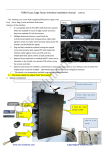
FV_PCM31_INT interface installation manual [Ver.121010] This interface can insert High definition RGB navigation video, AV and reverse camera video onto Porsche car screens[from 2011 and later]. The features are: Daughter board is used to insert video by switch the LVDS signal on ribbon cable. so the user can switch the video input in whatever mode.[navigation,DVD,car information etc]. CAN bus generated switch signal and reverse trigger signal. Guaranteed digital video quality on screen by full‐compatible oem LVDS encryption method. Plug and play connectors are used, the installer does not need to cut or modify any cable. Full digital circuit inside also guarantees the reliability. 1.System operations Input Switch: the user can press this CALL‐OFF key or the NAVI key to switch from car RGB AV1AV2 Car. 2. DIP switch setting: DIP =ON [DIP=Down side.] =OFF 1 RGB enabled RGB disabled. 2, AV1 for DVD enabled AV1 disabled 3 AV2 for Tuner or extra video enabled AV2disabled 4 RGB=HD RGB [800X480 or VGA 640X480] RGB=Normal NTSC [480X240] 5 This is reverse camera trigger wire go to CAM when Green wire= 12V] go to car video when Green wire= 12V 6 IR programme when once to ON Touch calibration when get to ON >5 times. OFF for normal work. 7,8 DIP7 no function. DIP8 UP=full reverse camera display DIP8 DOWN=mixed reverse camera display, the OEM radar picture will be shown the right 25% of screen. the left picture=DIP8 up. the right picture=DIP8 down. 1 / 4 3.System installation and connections: This video ribbon[Yellow arrow showed] is delivering video from main board to LCD PCB, it should be replaced to insert video: PNL‐OUT’s ribbon should be wired to the LCD panel. PCB‐IN’s ribbon should be wired to the main board. The total daughter board should be fixed to main board by screw in the accessory. Daughter board can be fixed on main PCB with Video ribbon connected. Daughter board’s TOP side with 4P touch connectors. The 2 touch connector here: The PNL_OUT should be wired to touch panel’s 4P plug. [use the extension ribbon in accessory with 4P socket.] The PCB‐in should be wired to the LCD’s touch 4P socket. The OEM touch panel connector. 2 / 4 LVDS to AV1,AV2 3 keys Touch daughter audio for color output board. switch tuning. to navi. The connectors are: RGB‐NAVI, AV1,AV2, reverse‐CAM. And 6P‐Power input. The CAN wires connection: name Car wires in above picture CAN bus wire CAN + CAN ‐ GND BATTor ACC Violet/orange twisted orange twisted Brown Red Blue twisted Gray twisted Brown Red with fuse [CAN wire wrong connection will not damage anything, an LED will be blinking when user press CD keys if correctly connected] The signal definition of 6P on interface from CAN box: Yellow:constant power of 12V。 black:GND of chassis。 RED[ACC]:when the monitor works, this wire=12V,otherwise=0V。 Green:reverse signal wire[=12V when in reverse], it can be used: To give reverse signal to interface box,also giving power to camera[max.1A] White wire:switch signal wire, when =12V or 5V, this interface switches. Gray wire:CAN bus control data to interface, it is used to pop up the control icons. See note2 on the end of this wire. 4.Interface Settings The 3 side keys are : menu, +,‐ respectively. When menu is press, OSD strings will pop up on screen, and the installer may adjust the best video effect. The +/‐ will change the value. The Postion H,Position V: these 2 options can be used to adjust the picture location on screen. The Guide Line option: can be used to enable/disable the parking guidelines. The DVD/TUNER/NAVI is to set the IR code output to the installed device, so people use original knob to control When set to “none”,the control icons will not pop out When set to “Prog”,the installer can use DIP6=Down to program the IR code into the interface, so extra new devices can be controlled. 5.CTRL port To navi There is a 8‐pin extra CTRL port on the interface, which the installer does not need to use in normal situation. For experienced users, this port may be used to get extra functions. One dedicated daughter board can be used, so people just touch the screen, the installed devices can be controlled by the icons, because the interface can generate IR code based on touch screen operations. To touch panel the CTRL port can be connected to the left touch cable, so DVD and other devices can be touch controlled. The internal switch makes the navi use touch panel 3 / 4 To CTRL port when in RGB‐input, and DVD uses the touch panel when in AV1 input. Ctrl port signal definitions: Pin 1,2 +5V output voltage for sound‐switch‐relay, when AV1 is selected=5V, 0V when AV2 selected. Max 3A. 3: Constant +5V Max .2A 4,8 Ground 5: Dedicated control bus for camera。 Should not be connected to GND, otherwise CPU will halt. 6: 7 +5V output when in interface mode, 0V when in Car mode. Note2: There is a gray wire between the can box and interface box, which is used to deliver control data, so that multimedia icons will pop out and be executed. This wire can also deliver terminal‐mode control data. So a 3rd party computer can control this interface.[ terminal mode like: to directly go to RGB input, to AV1 input, AV2 input,reverse camera input], to get the full implementation of fosp interface terminal mode operations, please contact fosp sales people. The programming of IR code: There are >10 types of DVD, NAVI, and Tuners’ IR code are stored inside the interface. The installer just adjusts the options to select to wanted one, then it works. If the wanted type is not there, he may set the option to be “Prog” in the menu to program the interface to replace new remote controllers. 1) When programming, switch the input to AV1, and set DIP6 down once, then the control icons will be shown, and one of the them will be blinking, which means the interface is waiting for an IR code. Then input one wanted IR code by using the gray wire of the power connector. [connecting the gray wire inside the power connector to the DVD or TV’s signal wire inside the ir sensor. There are usually 3 wires inside the ir sensor: +5V, GND, IR signal.] 2) When one ir code is sent to the interface, the blinking icon will be moved to the next one. Which means one code is programmed. Repeat this step until all icons are programmed. 3) The programming of AV2 is the same as above. When in normal use, please disconnect the IR sensor’s signal wire from the gray wire in power connector, but reconnect it to the gray‐wire‐in RGB connector. The pin7 marked with IR‐AV1/2. This is the IR output wire. 6. Parameters 4 / 4 No. name parameter 1 RGB video amplitude 0.7Vpp with 75 ohm impedance NTSC resolution [400X240,480X240] of navigation is allowed. 2 sync amplitude in RGB‐navi port 3~5Vpp with 5K ohm impedance Sync should be NTSC composite with negative polarity. 3 Av1,Av2, cam video amplitude 0.7Vpp with 75 ohm impedance 4 Av1,Av2, cam standard NTSC/PAL/SECAM automatic switch 5 6 Normal work Power consumption 2.4W [0.2A @12V] 7 Standby current < 5mA 8 Standby start 10 seconds after the users switch off the CD unit. 9 Reverse trigger threshold >5V trigger 10 Work temperature ‐40 ~ +85C 11 dimensions 15.6 X 9.2 X 2.2 Cm