1
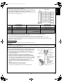
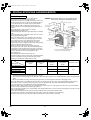
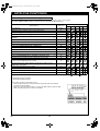
Outdoor Unit
Unité extérieure
Außengerät
Unità esterna
Unidad exterior
Εξωτερική µονάδα
Unidade exterior
Utomhusenhet
Наружный блок
RAS-4M23SAV-E
RAS-4M23SACV-E
RAS-3M26GAV-E
RAS-4M27GAV-E
RAS-4M27GACV-E
ESPAÑOL
For general public use
Pour utilisation grand public
Für allgemeine Verwendung
Per l’uso in generale
Para el uso público general
Για γενική δηµόσια χρήση
Para utilização geral
För allmän användning
Для общего бытового использования
ΕΛΛΗΝΙΚΑ
CLIMATISEUR (TYPE BLOCS MULTIPLES)
KLIMAGERÄT (MULTISYSTEM-SPLITGERÄT)
CONDIZIONATORE D’ARIA (TIPO MULTI-SPLIT)
ACONDICIONADOR DE AIRE (TIPO MÚLTI-SEPARADO)
ΚΛΙΜΑΤΙΣΤΙΚΗ ΜΟΝΑ∆Α (ΠΟΛΛΑΠΛΟΥ ΤΥΠΟΥ)
AR CONDICIONADO (TIPO MULTI-SPLIT)
LUFTKONDITIONERING (FLERSPLITTYP)
КОНДИЦИОНЕР (МУЛЬТИ-РАЗДЕЛИТЕЛЬНОГО
ТИПА)
ITALIANO
(MULTI-SPLIT TYPE)
PORTUGUÊS
AIR CONDITIONER
FRANÇAIS
MANUEL D’INSTALLATION DE L’UNITE
EXTERIEURE
EINBAUANLEITUNG FÜR DAS AUSSENGERÄT
MANUALE DI INSTALLAZIONE DELL’UNITÀ
ESTERNA
MANUAL DE INSTALACIÓN DE LA UNIDAD
EXTERIOR
ΕΓΧΕΙΡΙ∆ΙΟ ΕΓΚΑΤΑΣΤΑΣΗΣ ΕΞΩΤΕΡΙΚΗΣ
ΜΟΝΑ∆ΑΣ
MANUAL DE INSTALAÇÃO DA UNIDADE
EXTERIOR
INSTALLATIONSANVISNING FÖR
UTOMHUSENHETEN
ИНСТРУКЦИЯ ПО УСТАНОВКE НАРУЖНОГО
БЛОКА
DEUTSCH
OUTDOOR UNIT
INSTALLATION MANUAL
ENGLISH
OutdoorInstallation.book Page 0 Tuesday, February 13, 2007 5:58 PM
Lesen Sie diese Einbauanleitung sorgfältig durch, bevor Sie das Klimagerät installieren.
Prima di installare il condizionatore d’aria, si consiglia di leggere con attenzione il presente manuale di installazione.
Lea este manual de instalación atentamente antes de instalar el acondicionador de aire.
Παρακαλούµε διαβάστε αυτές τις οδηγίες εγκατάστασης προσεκτικά πριν εγκαταστήσετε την
κλιµατιστική µονάδα.
Leia atentamente este manual de instalação antes de instalar o ar condicionado.
Läs den här installationsanvisningen noga innan du installerar luftkonditioneringen.
Перед установкой кондиционера прочитайте, пожалуйста, внимательно эту инструкцию по
установке.
РУССКИЙ ЯЗЫК
Veuillez lire attentivement ce manuel avant d’installer le climatiseur.
SVENSKA
Please read this installation manual carefully before installing the air conditioner.
OutdoorInstallation.book Page i Tuesday, February 13, 2007 5:58 PM
CONTENTS/SOMMAIRE/INHALT/INDICE/ÍNDICE/ΠΕΡΙΕΧΟΜΕΝΑ/
ÍNDICE/INNEHÅLL/СОДЕРЖАНИЕ
ENGLISH
ΕΛΛΗΝΙΚΗ
1
2
3
4
5
6
7
1 ΠΡΟΦΥΛΑΞΕΙΣ ΑΣΦΑΛΕΙΑΣ ....................................... 1
2 ΠΡΟΑΙΡΕΤΙΚΑ ΑΝΤΑΛΛΑΚΤΙΚΑ, ΕΞΑΡΤΗΜΑΤΑ ΚΑΙ
ΕΡΓΑΛΕΙΑ ..................................................................... 3
3 ΠΟΙΑ ΜΟΝΤΕΛΑ ΜΠΟΡΟΥΝ ΝΑ ΣΥΝ∆ΥΑΣΤΟΥΝ ...... 5
4 ΕΓΚΑΤΑΣΤΑΣΗ ΕΞΩΤΕΡΙΚΗΣ ΜΟΝΑ∆ΑΣ ................... 6
5 ΓΕΙΩΣΗ ........................................................................ 12
6 ΕΛΕΓΧΟΣ ΚΑΙ ∆ΟΚΙΜΗ ΛΕΙΤΟΥΡΓΙΑΣ ...................... 12
7 ΧΡΗΣΙΜΕΣ ΛΕΙΤΟΥΡΓΙΕΣ .......................................... 14
SAFETY PRECAUTIONS ..............................................1
OPTIONAL PARTS, ACCESORIES AND TOOLS ........3
WHICH MODELS CAN BE COMBINED ........................5
INSTALLATION OF OUTDOOR UNIT ...........................6
GROUNDING ...............................................................12
CHECK AND TEST OPERATION ...............................12
USEFUL FUNCTIONS .................................................14
FRANÇAIS
PORTUGUÊS
1
2
3
4
MESURES DE SECURITE ............................................1
PIECES EN OPTION, ACCESSOIRES ET OUTILS .....3
QUELS MODELES PEUVENT ETRE COMBINES .......5
SYSTEME DE PRIORITES DE MODE DE
FONCTIONNEMENT .....................................................6
5 MISE A LA TERRE ......................................................12
6 CONTROLE ET OPERATION D’ESSAI ......................12
7 FONCTIONS UTILES ..................................................14
1 PRECAUÇÕES DE SEGURANÇA ................................ 1
2 PEÇAS OPCIONAIS, ACESSÓRIOS E
FERRAMENTAS ........................................................... 3
3 MODELOS QUE PODEM SER COMBINADOS ............ 5
4 INSTALAÇÃO DA UNIDADE EXTERIOR ..................... 6
5 LIGAÇÃO À TERRÀ .................................................... 12
6 VERIFICAÇÃO E TESTE DA OPERAÇÃO ................. 12
7 FUNÇÕES ÚTEIS ....................................................... 14
DEUTSCH
SVENSKA
1 SICHERHEITSVORKEHRUNGEN ................................1
2 SONDERTEILE, SONDERZUBEHÖR UND
WERKZEUGE ................................................................3
3 WELCHE MODELLE KÖNNEN KOMBINIERT
WERDEN .......................................................................5
4 INSTALLATION DES AUSSENGERÄTS ......................6
5 ERDUNG .....................................................................12
6 PRÜFUNG UND TESTBETRIEB .................................12
7 NÜTZLICHE FUNKTIONEN ........................................14
1 SÄKERHETSFÖRESKRIFTER ..................................... 1
2 TILLVALSUTRUSTNING, TILLBEHÖR OCH
VERKTYG ..................................................................... 3
3 VILKA MODELLER SOM GÅR ATT KOMBINERA ....... 5
4 INSTALLATION AV UTOMHUSENHETEN ................... 6
5 JORDNING .................................................................. 12
6 KONTROLL OCH TESTKÖRNING ............................. 12
7 PRAKTISKA FUNKTIONER ........................................ 14
ITALIANO
РУССКИЙ ЯЗЫК
1 PRECAUZIONI PER LA SICUREZZA ...........................1
2 COMPONENTI OPZIONALI, ACCESSORI E
STRUMENTI ..................................................................3
3 QUALI MODELLI É POSSIBILE COMBINARE .............5
4 INSTALLAZIONE DELL’UNIT À ESTERNA ..................6
5 MESSA A TERRA ........................................................12
6 CONTROLLI E FUNZIONAMENTO DI PROVA ..........12
7 FUNZIONI UTILI ..........................................................14
1 МЕРЫ ПРЕДОСТОРОЖНОСТИ ................................. 1
2 ДОПОЛНИТЕЛЬНЫЕ ЧАСТИ,
ПРИНАДЛЕЖНОСТИ И ИНСТРУМЕНТЫ .................. 3
3 КОМБИНАЦИЯ КАКИХ МОДЕЛЕЙ ВОЗМОЖНА ...... 5
4 УСТАНОВКА НАРУЖНОГО БЛОКА ........................... 6
5 ЗАЗЕМЛЕНИЕ ............................................................ 12
6 ПРОВЕРКА И ТЕСТОВАЯ ЭКСПЛУАТАЦИЯ .......... 12
7 УДОБНАЯ ФУНКЦИЯ ................................................ 14
ESPAÑOL
1 PRECAUCIONES SOBRE SEGURIDAD ......................1
2 PARTES OPCIONALES, ACCESORIOS Y
HERRAMIENTAS ..........................................................3
3 QUÉ MODELOS PUEDEN COMBINARSE ...................5
4 INSTALLATION DE LA UNIDAD EXTERIOR ................6
5 CONEXIÓN A TIERRA ................................................12
6 COMPROBACIÓN Y OPERACIÓN DE PRUEBA .......12
7 FUNCIÓN PRÁCTICA .................................................14
i
01_OutdoorInstallation_EN.fm Page 1 Friday, March 23, 2007 4:23 PM
ENGLISH
IMPORTANT NOTICE
• For details on how to install the indoor units, refer to the installation manual accompanying the indoor units.
1 SAFETY PRECAUTIONS
For general public use
• RAS-4M23SAV-E, RAS-4M23SACV-E
Power supply cord of outdoor unit shall be 1.5 mm2 (H07RN–F or 60245IEC66) polychloroprene sheathed flexible cord.
• RAS-3M26GAV-E, RAS-4M27GAV-E, RAS-4M27GACV-E
Power supply cord of outdoor unit shall be 2.5 mm2 (H07RN–F or 60245IEC66) polychloroprene sheathed flexible cord.
CAUTION
New Refrigerant Air Conditioner Installation
• THIS AIR CONDITIONER ADOPTS THE NEW HFC REFRIGERANT (R410A) WHICH DOES NOT DESTROY OZONE
LAYER.
R410A refrigerant is apt to be affected by impurities such as water, oxidizing membrane, and oils because the working pressure of
R410A refrigerant is approx. 1.6 times as that of refrigerant R22. Accompanied with the adoption of the new refrigerant, the
refrigeration machine oil has also been changed. Therefore, during installation work, be sure that water, dust, former refrigerant,
or refrigeration machine oil does not enter the new type refrigerant R410A air conditioner circuit.
To prevent mixing of refrigerant or refrigerating machine oil, the sizes of connecting sections of charging port on main unit and
installation tools are different from those of the conventional refrigerant units. Accordingly, special tools are required for the new
refrigerant (R410A) units as shown on page 4. For connecting pipes, use new and clean piping materials with high pressure
fittings made for R410A only, so that water and/or dust does not enter. Moreover, do not use the existing piping because there are
some problems with pressure fittings and possible impurities in existing piping.
CAUTION
TO DISCONNECT THE APPLIANCE FROM THE MAIN POWER SUPPLY
Disconnection from the supply mains:
The means for disconnection must be incorporated in the fixed wiring in accordance with the wiring rules.
1
EN
OutdoorInstallation.book Page 2 Tuesday, February 13, 2007 5:58 PM
DANGER
• FOR USE BY QUALIFIED PERSONS ONLY.
• TURN OFF MAIN POWER SUPPLY BEFORE ATTEMPTING ANY ELECTRICAL WORK. MAKE SURE ALL POWER
SWITCHES ARE OFF. FAILURE TO DO SO MAY CAUSE ELECTRIC SHOCK.
• CORRECTLY CONNECT THE CONNECTING CABLE. IF THE CONNECTING CABLE IS INCORRECTLY CONNECTED,
ELECTRIC PARTS MAY BE DAMAGED.
• CHECK THAT THE EARTH WIRE IS NOT BROKEN OR DISCONNECTED BEFORE INSTALLATION. FAILURE TO DO SO
MAY CAUSE ELECTRIC SHOCK.
• DO NOT INSTALL THE UNIT IN A PLACE WHERE INFLAMMABLE GAS CAN LEAK. A FIRE CAN RESULT IF
INFLAMMABLE GAS ACCUMULATES AROUND THE UNIT.
• TO PREVENT THE INDOOR UNIT FROM OVERHEATING AND CAUSING A FIRE HAZARD, PLACE THE UNIT WELL
AWAY (MORE THAN 2 M) FROM HEAT SOURCES SUCH AS RADIATORS, HEAT REGISTORS, FURNACE, STOVES,
ETC.
• WHEN MOVING THE AIR-CONDITIONER FOR INSTALLATION TO ANOTHER PLACE, BE VERY CAREFUL NOT TO
ALLOW THE SPECIFIED REFRIGERANT (R410A) TO BECOME MIXED WITH ANY OTHER GASEOUS BODY INTO THE
REFRIGERATION CIRCUIT. IF AIR OR ANY OTHER GAS MIXES WITH THE REFRIGERANT, THE GAS PRESSURE IN
THE REFRIGERATION CIRCUIT WILL BECOME ABNORMALLY HIGH AND IT MAY RESULT IN THE PIPE BURSTING OR
PERSONNEL INJURIES.
• IN THE EVENT THAT THE REFRIGERANT GAS LEAKS OUT OF THE PIPE DURING THE INSTALLATION WORK,
IMMEDIATELY LET FRESH AIR INTO THE ROOM. IF THE REFRIGERANT GAS IS HEATED, POISONOUS GAS MAY
RESULT.
• WHEN INSTALLING THE AIR CONDITIONER UNIT, MAKE SURE THAT THE REFRIGERANT PIPE IS CONNECTED
SECURELY BEFORE THE COMPRESSOR IS OPERATED. IF THE COMPRESSOR IS OPERATED WITH THE
REFRIGERANT PIPE UNCONNECTED, WHICH MEANS THAT THE SERVICE VALVE WILL BE LEFT OPEN, AIR, ETC.
WILL BE SUCKED IN, CAUSING THE PRESSURE INSIDE THE REFRIGERATION CYCLE TO RISE TO AN
ABNORMALLY HIGH LEVEL, AND POSSIBLY RESULTING IN RUPTURE, INJURY, ETC.
• WHEN CARRYING OUT THE PUMP-DOWN WORK, SHUT DOWN THE COMPRESSOR BEFORE DISCONNECTING
THE REFRIGERANT PIPE. DISCONNECTING THE REFRIGERANT PIPE WITH THE SERVICE VALVE LEFT OPEN AND
WITH THE COMPRESSOR STILL OPERATING WILL CAUSE AIR, ETC. TO BE SUCKED IN, RAISING THE PRESSURE
INSIDE THE REFRIGERATION CYCLE TO AN ABNORMALLY HIGH LEVEL, AND POSSIBLY RESULTING IN
RUPTURING, INJURY, ETC.
WARNING
• Never modify this unit by removing any of the safety guards.
• The installation of the air conditioner must be positioned in a location that can sufficiently support its weight. Failure to do so
may result in unit damage and human injury.
• Appliance shall be installed in accordance with national wiring regulations.
• If you detect any damage, do not install the unit. Contact your Toshiba dealer immediately.
CAUTION
• Exposure of unit to water or other moisture before installation may result in an electrical short. Do not store in a wet
basement or expose to rain or water.
• After unpacking the unit, examine it carefully for any damage.
• Do not install in a place that can increase the vibration of the unit. Do not install in a place that can amplify the noise level of
the unit or where noise or discharged air might disturb neighbors.
• To avoid personal injury, be careful when handling parts with sharp edges.
• Please read this installation manual carefully before installing the unit. It contains further important instructions necessary for
proper installation.
• Wear work gloves when carrying out the installation work or repairs. Contact with parts, etc. may cause injury if the work or
repairs are conducted without wearing gloves.
EN
2
OutdoorInstallation.book Page 3 Tuesday, February 13, 2007 5:58 PM
ENGLISH
2 OPTIONAL PARTS, ACCESORIES AND TOOLS
Optional Installation Parts
Part name
Refrigerant piping*1
Indoor unit name
(Abbreviation)
10, 13
16
Specifications
Liquid side
(Outer diameter)
6.35 mm
6.35 mm
Q’ty
Gas side
(Outer diameter)
9.52 mm
12.7 mm
1 ea.
Putty, PVC tapes
1 ea.
*1 Refrigerant piping covered with insulating material (polyethylene form, 6 mm thick).
* In case the piping is installed above the ceiling, it shall be covered with thicker insulating material (polyethylene form, 10 mm
thick).
259
• Secure the outdoor unit with the attachment bolts and nuts if the unit
is likely to be exposed to a strong wind.
• Use φ8 mm or φ10 mm anchor bolts and nuts.
• If it is necessary to drain the defrost water, attach drain nipple to the
base plate of the outdoor unit before installing it.
Suction side
50
280
42.5
365
50
40
Attachment bolt arrangement of outdoor unit
Diffuser
Elongated drain
hole
(d)
600
Drain hole
(c)
Accessory and Installation Parts
Part No.
Part name (Q’ty)
Part No.
a
c
Drain nipple x 1
(Heat pump models only)
Outdoor unit installation manual x 1
b
d
Water-proof rubber cap x 1
(Heat pump models only)
Specifications x 1
Others
Part name (Q’ty)
Name
Important information and warning
B/W strips (Energy efficiency labels)
3
EN
OutdoorInstallation.book Page 4 Tuesday, February 13, 2007 5:58 PM
Installation/Service Tools
Changes in the product and components
In air conditioners using R410A, in order to prevent any other refrigerant from being accidentally charged, the service port diameter
size of the outdoor unit control valve (3 way valve) has been changed. (1/2 UNF 20 threads per inch)
• In order to increase the pressure resisting strength of the refrigerant piping, flare processing diameter and opposing flare nuts sizes
have been changed. (for copper pipes with nominal dimensions 1/2 and 5/8)
New tools for R410A
New tools for R410A
Gauge manifold
Applicable to R22 model
Charge hose
Changes
As the working pressure is high, it is impossible to measure
the working pressure using conventional gauges. In order to
prevent any other refrigerant from being charged, the port
diameters have been changed.
In order to increase pressure resisting strength, hose
materials and port sizes have been changed (to 1/2 UNF 20
threads per inch).
When purchasing a charge hose, be sure to confirm the
port size.
As working pressure is high and gasification speed is fast, it
is difficult to read the indicated value by means of charging
cylinder, as air bubbles occur.
Electronic balance for refrigerant
charging
Torque wrench
(nominal dia. 1/2, 5/8)
The size of opposing flare nuts have been increased.
Incidentally, a common wrench is used for nominal
diameters 1/4 and 3/8.
Flare tool (clutch type)
By increasing the clamp bar’s receiving hole size, strength
of spring in the tool has been improved.
Gauge for projection adjustment
Vacuum pump adapter
—
Used when flare is made by using conventional flare tool.
Connected to conventional vacuum pump. It is necessary to
use an adapter to prevent vacuum pump oil from flowing
back into the charge hose. The charge hose connecting
part has two ports — one is for conventional refrigerant (7/
16 UNF 20 threads per inch) and the other is for R410A. If
the vacuum pump oil (mineral) mixes with R410A a sludge
may occur and damage the equipment.
Exclusive for HFC refrigerant.
Gas leakage detector
• Incidentally, the “refrigerant cylinder” comes with the refrigerant designation (R410A) and protector coating in the U.S’s ARI
specified rose color (ARI color code: PMS 507).
• Also, the “charge port and packing for refrigerant cylinder” requires 1/2 UNF 20 threads per inch corresponding to the charge hose’s
port size.
EN
4
OutdoorInstallation.book Page 5 Tuesday, February 13, 2007 5:58 PM
Table of models that can be connected
: Can be connected.
: Cannot be connected.
Slim Duct
Type
High Wall Type
Indoor unit
specification
Heat
pump
16-class
13-class
10-class
Outdoor unit
for
combination
With air purifying unit
DAISEIKAI 2 DAISEIKAI 3
RASRASB16GKVP-E
B16SKVP-E
RASRASB13GKVP-E
B13SKVP-E
RASRASB10GKVP-E
B10SKVP-E
Without air purifying unit
RASM16GKV-E
RASM13GKV-E
RASM10GKV-E
RASM16SKV-E
RASM13SKV-E
RASM10SKV-E
Coolingonly
16-class
13-class
10-class
Outdoor unit
for
combination
RASM16GDV-E
RASM13GDV-E
RASM10GDV-E
RASM16SMUV-E
RASM13SMUV-E
RASM10SMUV-E
RAS4M23SAV-E
RAS3M26GAV-E
RAS4M27GAV-E
Slim Duct
Type
High Wall Type
Indoor unit
specification
4-way Air
Discharge
Cassette
Type
With air purifying unit
DAISEIKAI 2 DAISEIKAI 3
RASRASM16GKCVP-E M16SKCVP-E
RASRASM13GKCVP-E M13SKCVP-E
RASRASM10GKCVP-E M10SKCVP-E
4-way Air
Discharge
Cassette
Type
Without air purifying unit
RASM16GKCV-E
RASM13GKCV-E
RASM10GKCV-E
RASM16SKCV-E
RASM13SKCV-E
RASM10SKCV-E
RASM16GDCV-E
RASM13GDCV-E
RASM10GDCV-E
RASM16SMUCV-E
RASM13SMUCV-E
RASM10SMUCV-E
RAS4M23SACV-E
RAS4M27GACV-E
NOTES
A 1-room connection is not an option for the indoor units (you cannot connect only one indoor unit). A 2-room or more connection
must always be used for the indoor units (you must connect at least two indoor units).
5
EN
ENGLISH
3 WHICH MODELS CAN BE COMBINED
OutdoorInstallation.book Page 6 Tuesday, February 13, 2007 5:58 PM
4 INSTALLATION OF OUTDOOR UNIT
Installation Location
• A place which provides enough space around the outdoor
unit as shown in the diagram.
• A place which can bear the weight of the outdoor unit and
does not allow an increase in noise level and vibration.
• A place where the operation noise and discharged air do not
disturb neighbors.
• A place which is not exposed to a strong wind.
• A place free of combustible gases.
• A place which does not block a passageway.
• When the outdoor unit is to be installed in an elevated
position, be sure to secure its feet.
• Piping connections to the outdoor unit should be arranged in
the sequence A, then B, C, D, starting from the bottom. (For
each piping connection, the gas pipe is on the bottom and the
liquid pipe on top.)
• When multiple indoor units are to be connected to the
outdoor unit, make sure the ends of the pipes and wires from
each indoor unit are connected to the outdoor unit correctly.
(Problems caused by indoor units being connected to the
outdoor unit incorrectly are very common in multiple-unit
installations.)
• The length and height differences of the connecting pipes
between the indoor and outdoor units must be within the
ranges indicated below.
NOTE: For installation, at least 3 sides should be kept
away from obstacles (walls).
600 mm or more
100 mm or more
from wall
100 mm or more
from wall
600 mm or
more from wall
600 mm or more
As shown in the figure, hang power cord
and connecting cable downward.
Allowable piping length and height difference
Item
Outdoor unit
RAS-4M23SAV-E
RAS-4M23SACV-E
RAS-3M26GAV-E
RAS-4M27GAV-E
RAS-4M27GACV-E
Piping length
Maximum for
Minimum for 1 unit Maximum for 1 unit
total of 3 units
2m
25 m
Maximum for
total of 4 units
—
60 m*1
50 m
—
—
70 m*2
Height difference
15 m
* The outdoor unit should not be installed with one indoor unit only. Be sure the (outdoor) unit is installed with at least two indoor
units.
*1 If the total piping length for the 4M23 is 40 m or more, add an extra 20 g/m of refrigerant.
*2 If a 4-way air discharge cassette type is connected to the 4M27, the maximum piping length is 50 m.
• If the outdoor unit is to be mounted on a wall, make sure the platform supporting it is sturdy enough.
The platform should be designed and manufactured to maintain its strength over a long period of time, and sufficient consideration
should be given to ensuring that the outdoor unit will not fall.
• When the outdoor unit is to be mounted high on a wall, take particular care to ensure that parts do not fall, and that the installer is
protected.
• When doing installation work at ground level, it is usual to make wiring and pipe connections to the indoor units, first, and then to
make connections to the outdoor unit.
However, if outdoor work is difficult it is possible, instead, to make changes to the procedure.
For example, by making adjustments to the wiring and piping lengths on the inside (rather than the outside).
• A place where the drain water does not cause any problems.
EN
6
OutdoorInstallation.book Page 7 Tuesday, February 13, 2007 5:58 PM
3.
4.
ENGLISH
CAUTION
1.
2.
Install the outdoor unit in a location where there are no obstructions near its air intake or air outlet.
When the outdoor unit is installed in a place that is always exposed to strong winds like on the coast or on a high story of a
building, secure the normal fan operation using a duct or a wind shield.
Especially in windy areas, install the unit to prevent the admission of wind.
Installation in the following places may result in trouble. Do not install the unit in such places.
• A place full of machine oil.
• A saline-place such as the coast.
• A place full of sulfide gas.
Strong
• A place where high-frequency waves are likely to be generated, such
wind
as from audio equipment, welders, and medical equipment.
Draining the water (heat pump models only)
A hole is provided on the base plate of the outdoor unit to ensure that the defrost water produced during heating operations is drained
off efficiently.
When the outdoor unit is to be installed in an area with a moderate
climate
• Allow the water in the outdoor unit to drip onto the ground.
• If a centralized drain is required, which is the case when the unit is installed on a
balcony or against a wall, follow the steps below.
Tips when using a drain pan and elbow
• When using a drain pan, check its dimensions before deciding where the
outdoor unit is to be installed.
• When the elbow supplied is to be used, be advised that its dimensions are as
shown in the figure. Ensure that the foundation does not protrude beyond
where the elbow and the part of the hose connected to it are to be installed.
Drain port
Outline of
drain pan
Outdoor unit
Outline of outdoor
unit
Drain pan
Elbow (with a 40 mm
outside diameter)
30
Foundation
• When draining off the water using a drain nipple
When a drain hose is to be used to drain the water, install the drain nipple and
water-proofing rubber cap shown in the figure, and use a commercially available
drain hose (16 mm inside diameter). Tightly seal the knock-out holes and screw/
thread areas using a silicon adhesive, etc. to ensure that there is no water
drippage. Under some conditions, condensation may form on the base plate and
drip down. When all the defrost water is to be drained off using a centralized
drain, use the drain pan.
80
• When a drain pipe is to be used to drain the water
• Use a drain pan to catch the defrost water, and drain the pan.
• Use a pipe made of hard PVC with a nominal diameter of 25A (25 mm inside
diameter) for the drain pipe.
Direction of air
blown out
58
d Water-proofing
rubber cap
c Drain nipple
When the outdoor unit is to be installed in an area with a snowy or
cold climate
• Allow the water in the outdoor unit to drip onto the ground. (Do not use a hose to
drain off the water.)
• The drain water may freeze inside the base plate at below freezing outside air
temperatures so use a screwdriver or other tool to open the knock-out holes in
the base plate.
The water will drain more efficiently when the knock-out holes are opened. (Use
a screwdriver or other tool to pull out the knock-out pieces.)
Knock-out holes
7
EN
OutdoorInstallation.book Page 8 Tuesday, February 13, 2007 5:58 PM
Refrigerant Piping Connection
Flaring
1.
Cut the pipe with a pipe cutter.
2.
Warp
Roughness
Obliquity
Insert a flare nut into the pipe, and flare the pipe.
• Projection margin in flaring: A (Unit: mm)
Rigid (Clutch type)
Outer diameter of copper pipe
6.35
9.52
12.7
Die
3.
R410A tool used
0 to 0.5
0 to 0.5
0 to 0.5
Conventional tool used
1.0 to 1.5
1.0 to 1.5
1.0 to 1.5
Imperial (Wing nut type)
Outer diameter of copper pipe
6.35
9.52
12.7
Pipe
R410A
1.5 to 2.0
1.5 to 2.0
2.0 to 2.5
Flaring size: B (Unit: mm)
B
Outer diameter of copper pipe
R410A
9.1
13.2
16.6
6.35
9.52
12.7
+0
–0.4
R22
9.0
13.0
16.2
• In case of flaring for R410A with the conventional flare tool, pull it out approx. 0.5 mm more than that of R22 to adjust the
specified flare size. The copper pipe gauge is useful for adjusting projection margin size.
Tighten the connection
Align the centers of the connecting pipes and tighten the flare nut as much as possible with your fingers. Then tighten the nut with a
wrench and torque wrench as shown in the figure.
Flare nut
Half union
Internally threaded side
Externally threaded side
Use a wrench to secure.
Use a torque wrench to tighten.
CAUTION
• Do not apply excessive force. Otherwise, the nut may break.
Outer diameter of copper pipe
φ6.35 mm
φ9.52 mm
φ12.7 mm
(Unit: N·m)
Tightening torque
14 to 18 (1.4 to 1.8 kgf·m)
33 to 42 (3.3 to 4.2 kgf·m)
50 to 62 (5.0 to 6.2 kgf·m)
Flare at indoor
unit side
Flare at outdoor
unit side
EN
8
OutdoorInstallation.book Page 9 Tuesday, February 13, 2007 5:58 PM
• Tightening torque for connection of flare pipe
The pressure of R410A is higher than R22. (Approx. 1.6 times.) Therefore
securely tighten the flare pipes which connect the outdoor unit and the indoor
unit with the specified tightening torque using a torque wrench.
If any flare pipe is incorrectly connected, it may cause not only a gas leakage
but also trouble in the refrigeration cycle.
ENGLISH
4M23, 4M27
φ6.35
Unit D
φ9.52
φ6.35
Unit C
φ9.52
φ6.35
Unit B
φ9.52
φ6.35
Unit A
φ9.52 or φ12.7
Outdoor unit
RAS-4M23SAV-E,
RAS-4M23SACV-E
Indoor unit
RAS-4M27GAV-E,
RAS-4M27GACV-E
RAS-3M26GAV-E
A
1 unit: 16 or 13 or 10
1 unit: 16 or 13 or 10
1 unit: 16 or 13 or 10
B
1 unit: 13 or 10
1 unit: 16 or 13 or 10
1 unit: 16 or 13 or 10
C
1 unit: 13 or 10
1 unit: 13 or 10
D
10
Total
46
1 unit: 13 or 10
1 unit: 13 or 10
45
52
* The unit A connection port diameter is φ6.35 / φ9.52 for the 4M23 and φ6.35 / φ12.7 for the 3M26 and 4M27.
* Use a different-diameter joint if the diameters of the connection port and connection piping are different.
* Only one 16-class indoor unit can be connected to the 4M23.
A 1-room connection is not an option for the indoor units (you cannot connect only one indoor unit).
A 2-room or more connection must always be used for the indoor units (you must connect at least two indoor units).
All combinations that do not exceed the “Total” number can be installed. Note that expanders and reducers may be required
depending on the combination method.
Evacuating
After the piping has been connected to the indoor unit, perform the air purge.
AIR PURGE
Evacuate the air in the connecting pipes and in the indoor unit using a vacuum pump. Do not use the refrigerant in the outdoor unit.
For details, see the vacuum pump manual.
Use a vacuum pump
Be sure to use a vacuum pump with counter-flow prevention function so that
oil inside the pump does not flow back into the air conditioner pipes when the
pump stops. (If oil inside the vacuum pump enters the air conditioner circuit
which uses R410A, trouble with the refrigeration system may develop.)
1. Connect the charge hose from the manifold valve to the service port of
the gas side packed valve.
2. Connect the charge hose to the port of the vacuum pump.
3. Open fully the low pressure side handle of the gauge manifold valve.
4. Operate the vacuum pump to begin evacuating. Perform evacuating for
about 35 minutes if the piping length is 70 meters (25 minutes for 50 total
meters) (assuming a pump capacity of 27 liters per minute). Confirm that
the compound pressure gauge reading is –101 kPa (–76 cmHg).
5. Close the low pressure valve handle of gauge manifold.
6. Open fully the valve stem of the packed valves (both sides of Gas and
Liquid).
7. Remove the charging hose from the service port.
8. Securely tighten the caps on the packed valves.
9. Perform steps 1 through 8 above on each connected indoor unit.
9
Compound pressure gauge
–101 kPa (–76 cmHg)
Handle Lo
Charge hose
(For R410A only)
Packed valve at
liquid side
Pressure gauge
Manifold valve
Handle Hi
(Keep full closed)
Charge hose
(For R410A only)
Vacuum pump adapter for
counter-flow prevention
(For R410A only)
Vacuum
pump
Service port
(Valve core (Setting pin))
Packed valve at gas side
EN
OutdoorInstallation.book Page 10 Tuesday, February 13, 2007 5:58 PM
CAUTION
• IMPORTANT POINTS FOR PIPING WORK
(1) Prevent dust and moisture from entering the pipes.
(2) Tighten connections carefully (between pipes and unit).
(3) Evacuate the air in the connecting pipes using a VACUUM PUMP.
(4) Check for gas leaks at all connections.
Packed valve handling precautions
• Open the valve stem until it touches the stopper. Once it is in contact with the stopper, refrain from applying any more force than is
necessary.
• Securely tighten the valve stem cap with torque in the following table:
Gas side
(φ12.7 mm)
50 to 62 N·m
(5.0 to 6.2 kgf·m)
Gas side
(φ9.52 mm)
33 to 42 N·m
(3.3 to 4.2 kgf·m)
Liquid side
(φ6.35 mm)
14 to 18 N·m
(1.4 to 1.8 kgf·m)
Service port
14 to 18 N·m
(1.4 to 1.8 kgf·m)
Hexagon wrench
is required.
4 mm
Wiring Connection
1.
2.
3.
4.
5.
6.
Remove the side panel and cord clamp from the outdoor unit.
Connect the connecting cable to the terminal as identified by the matching numbers on the terminal block of indoor and outdoor
unit.
Insert the power cord and the connecting cable fully into the terminal block and secure it tightly with screws.
Use vinyl tape, etc. to insulate the cords which are not going to be used. Locate them so that they do not touch any electrical or
metal parts.
Secure the power cord and the connecting cable with the cord clamp.
Attach the side panel on the outdoor unit.
Stripping length of connecting cable
1 2 3
L N
10
10
10
10
40
30
Earth line
40
30
Power cord
Connecting
cable
Earth line
4 unit (A + B + C + D) Multi
3 unit (A + B + C) Multi
Terminal block (Connecting cable)
Terminal block (Connecting cable)
Screw
Screw
Connecting cable
(B unit)
Connecting cable
(A unit)
EN
Connecting cable
(B unit)
Connecting cable
(D unit)
Connecting cable
(C unit)
Connecting cable
(A unit)
Power cord
10
Connecting cable
(C unit)
Power cord
01_OutdoorInstallation_EN.fm Page 11 Friday, March 23, 2007 4:23 PM
4 unit Multi
RASRAS4M23SAV-E
4M23SACV-E
Power source
Maximum running current
Installation fuse rating
Power cord
Connecting cable
13.8 A
13.8 A
16 A breaker or fuse
(all types can be used)
3 unit Multi
4 unit Multi
RASRASRAS3M26GAV-E
4M27GAV-E
4M27GACV-E
220–240V ~50Hz
220V ~60Hz
16.4 A
17.0 A
16.6 A
20 A breaker or fuse
(all types can be used)
H07RN–F or 60245IEC66 (1.5 mm2)
H07RN–F or 60245IEC66 (2.5 mm2)
mm2)
H07RN–F or 60245IEC66 (1.0 mm2)
H07RN–F or 60245IEC66 (1.0
ENGLISH
Model
CAUTION
• Incorrect wiring connection may cause electrical parts to burn out.
• Be sure to comply with local regulations/codes when running the wire from outdoor unit to indoor unit. (Size of wire and wiring
method etc.)
• Every wire must be securely connected.
• If incorrect or incomplete wiring is carried out, fire or smoke may result.
• Prepare the power supply for the exclusive use of the air conditioner.
11
EN
01_OutdoorInstallation_EN.fm Page 12 Friday, March 23, 2007 4:23 PM
5 GROUNDING
This air conditioner must be grounded without fail.
Grounding is necessary not only to safeguard against the possibility of receiving an electric shock but also to absorb both the static,
which is generated by high frequencies and held in the surface of the outdoor unit, and noise since the air conditioner incorporates a
frequency conversion device (called an inverter) in the outdoor unit. If the air conditioner is not grounded, users may receive an
electric shock if they touch the surface of the outdoor unit and that unit is charged with static.
6 CHECK AND TEST OPERATION
For R410A, use the leak detector exclusively manufactured for HFC refrigerant (R410A, R134a, etc.)
* The conventional leak detector for HCFC refrigerant (R22, etc.) cannot be used because its sensitivity for HFC refrigerant lowers to
approx. 1/40 of that manufactured exclusively for HFC refrigerant.
• Pressure of R410A becomes approx. 1.6 times that of R22. If
installation work has not completely finished, gas leaks may
occur in cases such as when pressure rises during operation.
• Check the flare nut connections, valve stem cap connections
and service port cap connections for gas leaks with a leak
detector or soap water.
Flare nut connections
(Indoor unit)
• Service port cap connection
• Valve stem cap connection
CAUTION
• Use a circuit breaker of a type that is not tripped by shock waves.
• Incorrect/incomplete wiring will cause electrical fires or smoke.
• Prepare the power source for exclusive use with the air conditioner.
Miswiring (Mis-piping) Check
Make sure that the wiring and piping for each room have the same alphabetical code (A, B, C, D).
Connect and secure the power cord.
Use the power cord/cables with thickness, type, and protective devices specified in this manual.
Insulate the unused cords (conductors) with PVC tape.
1.
2.
3.
4.
EN
Turn on the power breaker.
Open the side panel of the outdoor unit.
Set the indoor unit to COOL mode.
• It is unnecessary to set the temperature.
• Miswiring checks cannot be executed when the outdoor air temperature is 5°C or less.
Start the check.
• Disconnect the miswiring check connector (color: Red) from the inverter P.C. board.
12
Flare nut connections
(Outdoor unit)
5.
6.
7.
During checks (Check time 3 to 20 minutes).
• When an error described in the table below occurrs, check that operation stops and an error code is displayed on LED.
After checks, the check results are displayed on LED.
• The compressor stops when a miswiring (mis-pipng) error occurrs.
• Confirm the contents of the table below.
• Turn off the power breaker.
• Correct miswiring/mis-piping.
• Connect the miswiring check connector.
• Execute the check operation again.
• Automatically return to normal operation when conditions are normal.
Return to normal operation.
• To return to normal operation during check operation or after a miswiring (mis-piping) error has been determined, connect the
miswiring check connector.
Miswiring (mis-piping) check by LED Indication
• For this outdoor unit, self-miswiring (mis-piping) checks are possible using the five LEDs (1 Yellow + 4 Red).
* LEDs (D800 to D804) are provided on the inverter P.C. board.
LED
D800 D801 D802 D803 D804
Description
Normal operation (no error)
Checking A unit
Checking B unit
During check
Checking C unit
*1
Checking D unit
Crush/Clog of Pipe A
Crush/Clog of Pipe B
Crush/Clog of Pipe C
*1
Crush/Clog of Pipe D
Miswiring/Mis-piping or Crush/Clog of Pipe A, B
Miswiring/Mis-piping or Crush/Clog of Pipe A, C
*1
Check results
Miswiring/Mis-piping or Crush/Clog of Pipe A, D
Miswiring/Mis-piping or Crush/Clog of Pipe B, C
*1
Miswiring/Mis-piping or Crush/Clog of Pipe B, D
*1
Miswiring/Mis-piping or Crush/Clog of Pipe C, D
A, B, C Miswiring/Mis-piping
A, B, D Miswiring/Mis-piping
A, C, D Miswiring/Mis-piping
B, C, D Miswiring/Mis-piping
A, B, C, D Miswiring/Mis-piping
Packed valve stays closed
LED : Light Emitting Diode,
: LED ON,
: LED OFF,
: LED Flash
*1 4 unit Multi model only
Check mode
Normal operation
Short → Open
Short
Red
Yellow
Miswiring (mis-piping) check connector
(color: Red)
13
EN
ENGLISH
OutdoorInstallation.book Page 13 Tuesday, February 13, 2007 5:58 PM
OutdoorInstallation.book Page 14 Tuesday, February 13, 2007 5:58 PM
7 USEFUL FUNCTIONS
Self-Diagnosis by LED Indication
• For this outdoor unit, by referring to the 5 LED (1 Yellow + 4 Red) indicator lights, self-diagnosis is possible.
• LEDs (D800 to D804) are located on the sub-control board underneath the inverter.
Indoor alarm
code
Contents
Normal running
LED indication
D800 D801 D802 D803 D804
None
IGBT short circuit, Compressor motor rear short
14
Trouble on position detecting circuit
16
Trouble on current detecting circuit
17
OUTDOOR CONDENSOR PIPE TEMPERATURE SENSOR (TE) fault
*2
18
SUCTION PIPE TEMPERATURE SENSOR (TS) fault
*2
18
DISCHARGE PIPE TEMPERATURE SENSOR (TD) fault
19
Trouble on outdoor fan
1A
OUTDOOR TEMPERATURE SENSOR (TO) fault
1B
Trouble on compressor system
1C
GAS SIDE PIPE TEMPERATURE SENSOR a (TGa) fault
1C
GAS SIDE PIPE TEMPERATURE SENSOR b (TGb) fault
1C
GAS SIDE PIPE TEMPERATURE SENSOR c (TGc) fault
1C
GAS SIDE PIPE TEMPERATURE SENSOR d (TGd) fault
*1
1C
Gas leakage, TS sensor out of place, PMV fault, Sensor fault
1C
TE sensor out of place, INDOOR EVAPORATOR PIPE
SENSOR (TC) out of place, PMV fault, Sensor fault
1C
Indoor or outdoor miswiring, Gas leakage, TS/TC sensor out of place, PMV
fault, Sensor fault
1C
Communication trouble between MCU
1C
Compressor lock
1D
Trouble on discharge temperature, Gas leakage
1E
Compressor break down
1F
: LED ON,
*1 4 unit Multi model only
*2 Heat pump model only
• These LEDs do not normally light.
1. If trouble occurs, LED goes on according to the contents of trouble as shown in the table
above.
2. When two or more troubles occur, LEDs go on cyclically (alternately).
3. When the trouble is eliminated, LEDs go off.
Red
Yellow
EN
14
: LED OFF
03_OutdoorInstallation_GE.fm Page 1 Friday, March 23, 2007 4:25 PM
WICHTIGER HINWEIS
• Einzelheiten zur Installation der Innenraumgeräte finden Sie in deren Einbauanleitung.
1 SICHERHEITSVORKEHRUNGEN
Für allgemeine Verwendung
• RAS-4M23SAV-E, RAS-4M23SACV-E
Das Stromversorgungskabel für das Außengerät muss mit Polychloropren flexibel ummantelt sein und einen Leiterquerschnitt
von 1,5 mm2 (H07RN-F oder 60245IEC66) besitzen.
DEUTSCH
• RAS-3M26GAV-E, RAS-4M27GAV-E, RAS-4M27GACV-E
Das Stromversorgungskabel für das Außengerät muss mit Polychloropren flexibel ummantelt sein und einen Leiterquerschnitt
von 2,5 mm2 (H07RN-F oder 60245IEC66) besitzen.
VORSICHT
Installation eines Klimageräts mit neuartigem Kältemittel
• IN DIESEM KLIMAGERÄT WIRD DAS NEUARTIGE HFC-KÄLTEMITTEL (R410A) VERWENDET, DAS DIE OZONSCHICHT
NICHT SCHÄDIGT.
Das Kältemittel R410A ist anfällig für Verunreinigungen durch Wasser, Membranoxidation und Öle, da der Druck des Kältemittels
R410A etwa das 1,6-Fache des Drucks beim Kältemittel R22 beträgt. Zusammen mit dem neuen Kältemittel wird nun auch ein
anderes Kälteanlagenöl verwendet. Achten Sie daher bei der Installation darauf, dass kein Wasser, Staub, altes Kältemittel oder
altes Kälteanlagenöl in den Kühlkreislauf des Klimagerät mit dem neuen Kältemittel R410A gerät.
Damit es nicht zu einer Vermischung von Kältemittel und Kälteanlagenöl kommt, haben die Anschlüsse an den Einfüllöffnungen
des Hauptgeräts bzw. an den Installationswerkzeugen eine andere Größe als bei herkömmlichen Kältemitteln. Aus diesem Grund
sind für das neue Kältemittel (R410A) Spezialwerkzeuge erforderlich (siehe auf Seite 4). Verwenden Sie für die Rohrleitungen
neues, sauberes Rohrmaterial mit Hochdruckverschraubung speziell für R410A, so dass kein Wasser oder Staub eindringen
kann. Verwenden Sie auch nicht die vorhandenen Rohrleitungen, da die Verschraubungen nicht für den höheren Druck ausgelegt
sind und die Rohre verunreinigt sein können.
VORSICHT
ABTRENNEN DES GERÄTS VOM STROMNETZ
Abtrennen vom Stromnetz:
Das Trennelement muss entsprechend der Verdrahtungsregeln in die Festverdrahtung integriert sein.
1
DE
OutdoorInstallation.book Page 2 Tuesday, February 13, 2007 5:58 PM
GEFAHR
• NUR ZUR VERWENDUNG DURCH QUALIFIZIERTES FACHPERSONAL.
• VOR BEGINN DER ELEKTROARBEITEN IST UNBEDINGT DIE STROMZUFUHR ZU UNTERBRECHEN.
VERGEWISSERN SIE SICH, DASS ALLE SCHALTER UND SICHERUNGEN AUSGESCHALTET SIND. BEI
NICHTBEACHTUNG BESTEHT DIE GEFAHR VON STROMSCHLÄGEN.
• ACHTEN SIE DARAUF DASS ALLE ELEKTROKABEL ORDNUNGSGEMÄSS ANGESCHLOSSEN SIND. EIN
INKORREKTER ANSCHLUSS KANN BESCHÄDIGUNGEN DER ELEKTRISCHEN BAUTEILE ZUR FOLGE HABEN.
• VERGEWISSERN SIE SICH VOR DER MONTAGE, DASS DAS GERÄT EINWANDFREI GEERDET IST. BEI
NICHTBEACHTUNG BESTEHT DIE GEFAHR VON STROMSCHLÄGEN.
• INSTALLIEREN SIE DAS GERÄT NICHT AN EINEM ORT, AN DEM ENTZÜNDBARES GAS AUSTRETEN KÖNNTE.
WENN SICH ENTZÜNDBARES GAS UM DAS GERÄT HERUM ANSAMMELT, KANN EIN BRAND VERURSACHT
WERDEN.
• UM EINE ÜBERHITZUNG DES INNENRAUMGERÄTS UND DIE DAMIT VERBUNDENE BRANDGEFAHR ZU
VERHINDERN, IST DARAUF ZU ACHTEN, DASS DAS GERÄT IN AUSREICHENDEM ABSTAND (MINDESTENS 2 M)
VON WÄRMEQUELLEN WIE HEIZKÖRPERN UND STRAHLERN, ÖFEN USW. AUFGESTELLT WIRD.
• WENN DAS KLIMAGERÄT IN EINEN ANDEREN RAUM UMGESETZT WIRD, IST SORGFÄLTIG DARAUF ZU ACHTEN,
DASS DAS KÄLTEMITTEL (R410A) IM KÄLTEKREISLAUF NICHT MIT ANDEREN GASEN IN KONTAKT KOMMT. WENN
LUFT ODER ANDERE GASE MIT DEM KÄLTEMITTEL VERMISCHT WERDEN, KANN DIES ZUM ÜBERMÄSSIGEN
ANSTEIGEN DES BETRIEBSDRUCKS, ZUM PLATZEN VON ROHREN ODER ZU VERLETZUNGEN FÜHREN.
• WENN WÄHREND DER EINBAUARBEITEN KÄLTEMITTEL AUS DER ROHRLEITUNG ENTWEICHT, MUSS DER RAUM
SOFORT DURCHLÜFTET WERDEN. BEIM ERHITZEN DES KÄLTEMITTELS KÖNNEN SICH GIFTIGE GASE BILDEN.
• VERGEWISSERN SIE SICH BEIM INSTALLIEREN DES KLIMAGERÄTS, DASS DIE KÜHLMITTELLEITUNG VOR DEM
BETRIEB DES KOMPRESSORS ORDNUNGSGEMÄSS ANGESCHLOSSEN IST. WENN DER KOMPRESSOR OHNE
ANGESCHLOSSENE KÜHLMITTELLEITUNG BETRIEBEN WIRD, BLEIBT DAS SERVICEVENTIL GEÖFFNET, LUFT
WIRD ANGESAUGT, UND DER DRUCK IM KÄLTEKREISLAUF STEIGT ÜBERMÄSSIG AN. ES BESTEHT EXPLOSIONSUND VERLETZUNGSGEFAHR USW.
• ACHTEN SIE BEIM EVAKUIEREN DARAUF, DEN KOMPRESSOR ABZUSCHALTEN, BEVOR SIE DAS
KÄLTEMITTELROHR ABTRENNEN. FALLS DAS KÄLTEMITTELROHR BEI OFFENEM SERVICEVENTIL UND
WEITERHIN IN BETRIEB BEFINDLICHEM KOMPRESSOR ABGETRENNT, WIRD LUFT USW. EINGESAUGT, SO DASS
DER DRUCK IM KÄLTEKREISLAUF ÜBERMÄSSIG ANSTEIGT, WAS ZU PLATZEN, VERLETZUNGEN USW. FÜHREN
KANN.
WARNUNG
• Dieses Gerät darf niemals so verändert werden, dass die Sicherheitseinrichtungen entfernt werden.
• Das Klimagerät muss an einer Stelle installiert werden, die für das Gewicht des Geräts ausreichende Tragfestigkeit besitzt.
Anderenfalls besteht die Gefahr, dass das Gerät beschädigt wird und Personen verletzt werden.
• Der Einbau des Geräts muss in Übereinstimmung mit den geltenden Verdrahtungsvorschriften erfolgen.
• Wenn ein Defekt festgestellt wird, darf das Gerät nicht installiert werden. Wenden Sie sich in diesem Fall unverzüglich an
Ihren Toshiba-Händler.
VORSICHT
• Der Kontakt der Anlage mit Wasser oder Feuchtigkeit vor der Installation kann einen elektrischen Kurzschluss zur Folge
haben. Lagern Sie das Gerät nicht in einem feuchten Keller, und schützen Sie es unbedingt vor Regen und Wasser.
• Überprüfen Sie das Gerät nach dem Auspacken sorgfältig auf mögliche Schäden.
• Installieren Sie das Gerät nicht an Orten, an denen die Vibrationen des Geräts verstärkt werden. Installieren Sie das Gerät
nicht an Orten, an denen sich das Betriebsgeräusch verstärken kann bzw. an denen Nachbarn durch Geräusch und Abluft
belästigt werden könnten.
• Um Verletzungen zu vermeiden, sind scharfkantige Teile mit besonderer Vorsicht zu handhaben.
• Lesen Sie diese Einbauanleitung sorgfältig durch, bevor Sie das Gerät installieren. Die Anleitung enthält weitere wichtige
Hinweise, um eine korrekte Montage der Geräte zu gewährleisten.
• Führen Sie jegliche Art von Installationsarbeiten, einschließlich von Reparaturen, grundsätzlich mit Schutzhandschuhen aus.
Werden Arbeiten ohne Schutzhandschuhe ausgeführt, kann eine Berührung von Teilen usw. mit bloßen Händen
Verletzungen verursachen.
DE
2
OutdoorInstallation.book Page 3 Tuesday, February 13, 2007 5:58 PM
2 SONDERTEILE, SONDERZUBEHÖR UND WERKZEUGE
Zusätzlich erhältliche Installationsteile
Bauteilname
Kältemittelrohrleitung*1
Name des Innenraumgeräts
(Abkürzung)
10, 13
16
Spezifikationen
Flüssigkeitsseite
(Außendurchmesser)
6,35 mm
6,35 mm
Menge
Gasseite
(Außendurchmesser)
9,52 mm
12,7 mm
je 1
Dichtungsmasse,
PVC-Bänder
je 1
259
• Befestigen Sie das Außengerät mit den Befestigungsschrauben und
Muttern, falls es starkem Wind ausgesetzt sein könnte.
• Verwenden Sie Ankerschrauben und Muttern mit φ8 mm oder φ10 mm.
• Falls das Ablassen von Tauwasser erforderlich ist, bringen Sie vor der
Installation einen Ablaufnippel in die Grundplatte des Außengeräts an.
Ansaugseite
50
280
42,5
365
50
40
Anordnung der Befestigungsschrauben für das Außengerät
DEUTSCH
*1 Kältemittelrohrleitung mit Isolierung (Polyethylenschaum, 6 mm dick).
* Wenn die Leitung über der Decke installiert wird, muss sie mit einer dickeren Isolierung umhüllt werden (Polyethylenschaum,
10 mm dick).
Blasluftverteiler
Erweiterte
Ablauföffnung
(d)
600
Ablauföffnung
(c)
Zubehör und Installationsteile
Teile-Nr.
Bauteilname (Menge)
Teile-Nr.
a
c
Ablaufnippel x 1
(Nur bei Modellen mit Wärmepumpe)
Einbauanleitung für das Außengerät x 1
b
d
Wasserdichte Gummikappe x 1
(Nur bei Modellen mit Wärmepumpe)
Spezifikationen x 1
Sonstiges
Bauteilname (Menge)
Name
Wichtige Informationen und Warnung
Schwarzweiße Streifen
(Energieeffizienz-Aufkleber)
3
DE
OutdoorInstallation.book Page 4 Tuesday, February 13, 2007 5:58 PM
Installations- und Wartungswerkzeuge
Änderungen am Produkt und an den Komponenten
Für Klimageräte, die mit R410A arbeiten, wurde der Durchmesser des Serviceanschlusses am Steuerventil des Außengeräts
(3-Wege-Ventil) geändert, so dass nicht versehentlich ein anderes Kältemittel eingefüllt werden kann. (1/2 UNF-Feingewinde,
20 Gewindedrehungen pro Zoll)
• Um die Druckfestigkeit der Kältemittelleitungen zu erhöhen, wurden der Bördeldurchmesser und die Größe der Bördelmuttern
geändert. (für Kupferleitungen mit Nennabmessung von 1/2 und 5/8)
Neue Werkzeuge für R410A
Neue Werkzeuge für R410A
Manometerblock
Anwendbar für Modell R22
Einfüllschlauch
Änderungen
Wegen des hohen Drucks ist eine Messung mit einem
herkömmlichen Manometer nicht möglich. Damit kein
anderes Kältemittel eingefüllt werden kann, wurde der
Anschlussdurchmesser geändert.
Um die Druckfestigkeit zu erhöhen, wurden die
Schlauchmaterialien und die Anschlussgrößen geändert (in
1/2 UNF-Feingewinde, 20 Gewindedrehungen pro Zoll).
Überprüfen Sie beim Kauf eines Einfüllschlauchs unbedingt
den Anschlussdurchmesser.
Wegen des hohen Drucks und der schnellen Gasbildung
lässt sich der am Einfüllzylinder angezeigte Wert nur
schwer lesen, da es zur Blasenbildung kommt.
Elektronisches Dosiergerät zum
Befüllen des Kältemittels
Drehmomentschlüssel
(Nenndurchmesser 1/2, 5/8)
Der Durchmesser der Bördelmuttern wurde vergrößert. Für
Nenndurchmesser von 1/4 und 3/8 wird ein normaler
Schraubenschlüssel verwendet.
Bördelwerkzeug (Kuppeltyp)
Durch eine Vergrößerung der Aufnahmeöffnung des
Anpressstabs konnte die Stärke der Feder im Werkzeug
verbessert werden.
Messgerät für Überstandseinstellung
Wird beim Bördeln mit einem herkömmlichen
Bördelwerkzeug verwendet.
Verbunden mit herkömmlicher Vakuumpumpe. Ein Adapter
muss verwendet werden, damit kein Öl aus der
Vakuumpumpe zurück in den Einfüllschlauch fließt. Das
Anschlussstück des Einfüllschlauchs hat zwei Öffnungen,
eine für herkömmliches Kältemittel (7/16 UNF-Feingewinde,
20 Gewindedrehungen pro Zoll) und eine für R410A. Wenn
sich das Vakuumpumpenöl (Mineralöl) mit R410A
vermischt, kann es zu Schlammbildung kommen, die das
Gerät beschädigt.
Nur für HFC-Kältemittel.
—
Vakuumpumpenadapter
Gasleckdetektor
• Der „Kältemittelzylinder“ wird mit der Kältemittelbezeichnung R410A und einer rosafarbenen Schutzbeschichtung (amerikanischer
ARI-Farbcode: PMS 507) geliefert.
• Für die „Einfüllöffnung und das Abpacken des Kältemittelzylinders“ ist ein 1/2 UNF-Feingewinde mit 20 Gewindedrehungen pro Zoll
erforderlich, das der Öffnung am Einfüllschlauch entspricht.
DE
4
OutdoorInstallation.book Page 5 Tuesday, February 13, 2007 5:58 PM
3 WELCHE MODELLE KÖNNEN KOMBINIERT WERDEN
Tabelle mit den Modellen, die angeschlossen werden können
: Kann angeschlossen werden.
: Kann nicht angeschlossen werden.
Hochwandgerät
Klasse 16
Klasse 13
Wärmepumpe
Klasse 10
Außengerät
zum
Kombinieren
RASM16GKV-E
RASM13GKV-E
RASM10GKV-E
Nur Kühlbetrieb
Klasse 16
Klasse 13
Klasse 10
Außengerät
zum
Kombinieren
RASM16GDV-E
RASM13GDV-E
RASM10GDV-E
RASM16SMUV-E
RASM13SMUV-E
RASM10SMUV-E
RAS4M23SAV-E
RAS3M26GAV-E
RAS4M27GAV-E
Hochwandgerät
Spezifikation
Innenraumgerät
RASM16SKV-E
RASM13SKV-E
RASM10SKV-E
4-WegeKassettengerät
DEUTSCH
Spezifikation
Innenraumgerät
Mit Luftreinigungseinheit
DAISEIKAI 2 DAISEIKAI 3
RASRASB16GKVP-E
B16SKVP-E
RASRASB13GKVP-E
B13SKVP-E
RASRASB10GKVP-E
B10SKVP-E
Flaches
Kanalgerät
Ohne Luftreinigungseinheit
Mit Luftreinigungseinheit
DAISEIKAI 2 DAISEIKAI 3
RASRASM16GKCVP-E M16SKCVP-E
RASRASM13GKCVP-E M13SKCVP-E
RASRASM10GKCVP-E M10SKCVP-E
RASM16GKCV-E
RASM13GKCV-E
RASM10GKCV-E
Flaches
Kanalgerät
Ohne Luftreinigungseinheit
RASM16SKCV-E
RASM13SKCV-E
RASM10SKCV-E
RASM16GDCV-E
RASM13GDCV-E
RASM10GDCV-E
4-WegeKassettengerät
RASM16SMUCV-E
RASM13SMUCV-E
RASM10SMUCV-E
RAS4M23SACV-E
RAS4M27GACV-E
HINWEIS
Ein 1-Raum-Anschluss ist bei den Innenraumgeräten nicht möglich (Sie können kein einzelnes Innenraumgerät anschließen). Die
Innenraumgeräte müssen mindestens in 2 Räumen verwendet werden (Sie müssen mindestens zwei Innenraumgeräte
anschließen).
5
DE
OutdoorInstallation.book Page 6 Tuesday, February 13, 2007 5:58 PM
4 INSTALLATION DES AUSSENGERÄTS
Aufstellungsort
• Wählen Sie einen Ort mit ausreichen Platz um das
Außengerät, wie in der Zeichnung dargestellt.
• Stellen Sie das Gerät an einem Ort auf, der das Gewicht des
Geräts aufnehmen kann und an dem das Betriebsgeräusch
sowie die Vibrationen des Geräts nicht verstärkt werden.
• Wählen Sie einen Ort, an dem das Geräusch bzw. die
Auslassluft nicht zu einer Belästigung der Nachbarn führen
könnte.
• Der Aufstellungsort sollte möglichst vor starker
Windeinwirkung geschützt sein.
• Am Aufstellungsort dürfen keine brennbaren Gase vorhanden
sein.
• Das Gerät darf nicht so aufgestellt werden, dass es zu einer
Durchgangsbehinderung führt.
• Wenn das Außengerät in einer erhöhten Position montiert
werden soll, müssen die Füße unbedingt gesichert werden.
• Die Leitungsanschlüsse zum Außengerät sollten in der
Reihenfolge A, B, C, D angeordnet werden, von unten
beginnend. (Bei allen Leitungsanschlüssen ist die Gasleitung
unten und die Flüssigkeitsleitung oben.)
• Beim Anschließen mehrerer Innenraumgeräte an das
Außengerät achten Sie darauf, dass die Rohrleitungsenden
und Drähte korrekt am Außengerät angeschlossen werden.
(Bei Multisystem-Installationen treten häufig Probleme durch
falsches Anschließen der Innenraumgeräte an das
Außengerät auf.)
• Die Rohrlängen und Höhenunterschiede der
Anschlussleitungen zwischen Innenraum- und Außengeräten
müssen innerhalb der unten genannten Bereiche liegen.
HINWEIS: Beim Einbau dürfen sich an mindestens drei
Seiten keine Hindernisse (Wände) befinden.
600 mm oder mehr
100 mm oder mehr
von der Wand
100 mm oder mehr
von der Wand
600 mm
oder mehr
von der
Wand
600 mm oder mehr
Lassen Sie das Netz- und Anschlusskabel
nach unten hängen (siehe Abbildung).
Zulässige Leitungslänge und Höhenunterschied
Detail
Außengerät
RAS-4M23SAV-E
RAS-4M23SACV-E
RAS-3M26GAV-E
RAS-4M27GAV-E
RAS-4M27GACV-E
Minimum für 1
Gerät
2m
Leitungslänge
Maximum für
Maximum für 1
insgesamt 3
Gerät
Geräte
25 m
Maximum für
insgesamt 4
Geräte
—
60 m*1
50 m
—
—
70 m
Höhenunterschied
15 m
*2
*
Es ist nicht zulässig, am Außengerät nur ein einzelnes Innenraumgerät anzuschließen. Sorgen Sie dafür, dass mindestens zwei
Innenraumgeräte am Außengerät angeschlossen werden.
*1 Wenn die Gesamtleitungslänge für das 4M23 über 40 m hinausgeht, fügen Sie pro zusätzlichem Meter weitere 20 g Kältemittel
hinzu.
*2 Wenn an das 4M27 ein 4-Wege-Kassettengerät angeschlossen wird, beträgt die maximale Leitungslänge 50 m.
• Wenn das Außengerät an einer Wand montiert werden soll, vergewissern Sie sich, dass die tragende Plattform stabil genug ist.
Die Plattform sollte so konstruiert und gefertigt sein, dass ihre Festigkeit über lange Zeit erhalten bleibt. Außerdem muss
sichergestellt sein, dass das Außengerät nicht herunterfallen kann.
• Wenn das Außengerät hochliegend an einer Wand montiert werden soll, muss sichergestellt sein, dass keine Teile herunterfallen
können und dass der Monteur vor Unfällen geschützt ist.
• Bei einer Montage im Erdgeschoss werden Kabel und Leitungen üblicherweise zuerst an die Innenraumgeräte angeschlossen und
dann an das Außengerät.
Wenn die Außenarbeiten schwierig sind, kann dieser Ablauf jedoch nach Bedarf geändert werden.
Die Anpassung der Kabel- und Leitungslängen kann z.B. im Innenraum stattfinden (anstatt draußen).
• Stellen Sie das Gerät an einem Ort auf, an dem das Ablaufwasser keine Probleme verursacht.
DE
6
OutdoorInstallation.book Page 7 Tuesday, February 13, 2007 5:58 PM
VORSICHT
1.
2.
3.
4.
Montieren Sie das Außengerät an einer Stelle, an der sich in der Nähe von Lufteinlass und Luftauslass keine Hindernisse
befinden.
Wenn das Außengerät an einer Stelle montiert wird, die starken Windeinwirkungen ausgesetzt ist (z.B. in Meeresnähe
oder in den oberen Stockwerken eines Hochhauses), muss das Gebläse mit einem Mantel oder Windschutz ausgestattet
werden, damit ein normaler Betrieb gewährleistet ist.
In Gebieten mit starken Winden ist das Gerät an windgeschützten Stellen zu installieren.
Eine Installation an folgenden Orten kann zu Problemen führen. Installieren Sie das Gerät daher nicht an solchen Orten.
• Orte, die mit Maschinenöl verunreinigt sind.
• Salzreiche Umgebung, zum Beispiel an der Küste.
• Orte mit starker Schwefelgas-Belastung.
• Orte mit Hochfrequenzsignalen, die z.B. durch Audiogeräte,
Schweißgeräte und medizinische Geräte erzeugt werden.
DEUTSCH
Starker
Wind
Ablassen des Wassers (nur bei Modellen mit Wärmepumpe)
Um sicherzustellen, dass das Tauwasser, das sich während des Heizbetriebs bildet, gut ablaufen kann, befindet sich eine Öffnung in
der Bodenplatte des Außengeräts.
Wenn das Außengerät in einer Gegend mit mildem Klima installiert
wird
Richtung der
ausgeblasenen
Luft
• Lassen Sie das Wasser aus dem Außengerät auf den Boden abtropfen.
• Wenn ein zentraler Ablauf erforderlich ist (falls die Außeneinheit auf einem
Balkon oder an einer Wand installiert ist) führen Sie die folgenden Schritte aus.
• Wenn für das Ablaufen des Wassers eine Ablaufleitung erforderlich ist
• Verwenden Sie zum Auffangen des Tauwassers eine Ablaufwanne, und
leeren Sie die Wanne.
• Verwenden Sie als Ablaufleitung ein Rohr aus Hart-PVC mit einem
Innendurchmesser von 25 mm.
Außengerät
Ablaufwanne
Rohrbogen (mit 40 mm
Außendurchmesser)
30
Unterbau
• Wenn das Wasser über einen Ablaufnippel abfließt
Wenn zum Abfließen des Wassers ein Schlauch verwendet werden soll, bringen
Sie den abgebildeten Ablaufnippel und die wasserdichte Gummikappe an, und
verwenden Sie einen handelsüblichen Ablaufschlauch (16 mm
Innendurchmesser). Dichten Sie die vorgestanzten Löcher und die Bereiche um
Schrauben/Gewinde mit Silikondichtmasse ab, damit kein Wasser austreten
kann. Unter Umständen kann sich an der Grundplatte Kondenswasser bilden
und heruntertropfen. Wenn das gesamte Tauwasser über den zentralen Ablauf
abgelassen werden soll, verwenden Sie die Ablaufwanne.
Umriss des
Außengeräts
80
Tipps beim Verwenden von Ablaufwanne und Rohrbogen
• Wenn Sie eine Ablaufwanne verwenden, prüfen Sie die Maße, bevor Sie den
Installationsort des Außengeräts festlegen.
• Wenn Sie den mitgelieferten Rohrbogen verwenden, achten Sie auf dessen
Maße, die in der Abbildung angegeben sind. Achten Sie darauf, dass der
Unterbau nicht über die Stelle hinausragt, an der der Rohrbogen und das
daran angeschlossene Leitungsstück installiert werden.
Ablauföffnung
Umriss der
Ablaufwanne
58
d Wasserdichte
Gummikappe
c Ablaufnippel
Wenn das Außengerät in einer Gegend mit Schneefall bzw. kaltem
Klima installiert werden soll
• Lassen Sie das Wasser aus dem Außengerät auf den Boden abtropfen.
(Verwenden Sie zum Ablassen des Wassers keinen Schlauch.)
• Das Wasser kann bei Temperaturen unter dem Gefrierpunkt auf der Grundplatte
gefrieren. Öffnen Sie deshalb die vorgestanzten Löcher in der Grundplatte mit
einem Schraubendreher oder einem anderen Werkzeug.
* Das Wasser kann besser abfließen, wenn die vorgestanzten Löcher offen sind.
(Heben Sie die ausgestanzten Teile mit einem Schraubendreher oder einem
anderen Werkzeug heraus.)
7
Vorgestanzte Löcher
DE
OutdoorInstallation.book Page 8 Tuesday, February 13, 2007 5:58 PM
Anschließen der Kältemittelleitungen
Bördeln
1.
Schneiden Sie das Rohr mit einem Rohrschneider.
schief
2.
verformt
uneben
Setzen Sie eine Bördelmutter in das Rohr ein, und bördeln Sie das Rohr.
• Überstand beim Bördeln: A (Einheit: mm)
Rigid (Kupplungstyp)
Außendurchmesser Kupferrohr
Bei Verwendung von R410A-Werkzeug
6,35
9,52
12,7
0 bis 0,5
0 bis 0,5
0 bis 0,5
Pressring
3.
Bei Verwendung von herkömmlichem
Werkzeug
1,0 bis 1,5
1,0 bis 1,5
1,0 bis 1,5
Imperial (Typ Flügelmutter)
Außendurchmesser Kupferrohr
6,35
9,52
12,7
Rohr
R410A
1,5 bis 2,0
1,5 bis 2,0
2,0 bis 2,5
Bördelweite: B (Einheit: mm)
B
Außendurchmesser Kupferrohr
+0
–0,4
R410A
R22
6,35
9,1
9,0
9,52
13,2
13,0
12,7
16,6
16,2
• Falls das R410A-Rohr mit einem herkömmlichen Bördelwerkzeug aufgeweitet werden soll, ziehen Sie es ca. 0,5 mm weiter
heraus als das R22-Rohr, um es auf die angegebene Bördelweite anzupassen. Um die Größe des Überstands anzupassen, ist
eine Rohrlehre sinnvoll.
Festziehen der Verbindung
Richten Sie die anzuschließenden Rohre in Richtung der Anschlüsse aus, und drehen Sie dann die Bördelmutter so weit wie möglich
mit den Fingern fest. Ziehen Sie die Mutter mit Schlüssel und Drehmomentschlüssel fest (siehe Abbildung).
Bördelmutter
Verbindungsstutzen
Seite mit Innengewinde
Seite mit Außengewinde
Mit Schlüssel sichern.
Mit Drehmomentschlüssel festziehen.
VORSICHT
• Achten Sie darauf, das die Mutter nicht zu fest angezogen wird. Anderenfalls kann die Mutter zerbrechen.
Außendurchmesser Kupferrohr
φ6,35 mm
φ9,52 mm
φ12,7 mm
(Einheit: N·m)
Anzugsdrehmoment
14 bis 18 (1,4 bis 1,8 kgf·m)
33 bis 42 (3,3 bis 4,2 kgf·m)
50 bis 62 (5,0 bis 6,2 kgf·m)
Verschraubung an
Innenraumgerät
Verschraubung an
Außengerät
DE
8
OutdoorInstallation.book Page 9 Tuesday, February 13, 2007 5:58 PM
• Anzugsdrehmoment für die Rohrverschraubung
Der Druck von R410A ist höher als der von R22. (ca. 1,6-fach.) Sichern Sie
daher die verschraubten Rohre zwischen Innenraumgerät und Außengerät mit
einem Drehmomentschlüssel und dem angegebenen Anzugsdrehmoment.
Bei falsch verschraubten Rohrverbindungen tritt nicht nur Gasleck aus, es gibt
auch Probleme mit dem Kältekreislauf.
4M23, 4M27
φ6,35
Gerät D
φ9,52
φ6,35
Gerät C
φ9,52
φ6,35
Gerät B
φ9,52
φ6,35
Gerät A
φ9,52 oder φ12,7
Innenraumgerät
RAS-4M23SAV-E,
RAS-4M23SACV-E
RAS-3M26GAV-E
RAS-4M27GAV-E,
RAS-4M27GACV-E
A
1 Gerät: 16 oder 13 oder 10
1 Gerät: 16 oder 13 oder 10
1 Gerät: 16 oder 13 oder 10
B
1 Gerät: 13 oder 10
1 Gerät: 16 oder 13 oder 10
1 Gerät: 16 oder 13 oder 10
C
1 Gerät: 13 oder 10
1 Gerät: 13 oder 10
D
10
Insgesamt
46
DEUTSCH
Außengerät
1 Gerät: 13 oder 10
1 Gerät: 13 oder 10
45
52
* Der Anschlussdurchmesser von Gerät A beträgt φ6,35 / φ9,52 (Modell 4M23) und φ6,35 / φ12,7 (Modelle 3M26 und 4M27).
* Wenn sich die Durchmesser von Anschluss und Leitung unterscheiden, verwenden Sie ein Reduzierstück.
* An das 4M23 kann nur ein Innenraumgerät der Klasse 16 angeschlossen werden.
Ein 1-Raum-Anschluss ist bei den Innenraumgeräten nicht möglich (Sie können kein einzelnes Innenraumgerät anschließen).
Die Innenraumgeräte müssen mindestens in 2 Räumen verwendet werden (Sie müssen mindestens zwei Innenraumgeräte
anschließen).
Alle Kombinationen, die nicht die Zahl unter „Insgesamt“ überschreiten, können installiert werden. Beachten Sie, dass entsprechend
der Kombinationsmethode ggf. Erweiterungs- und Reduzierstücke erforderlich sind.
Evakuieren
Wenn die Rohrleitungen an das Innenraumgerät angeschlossen sind, führen Sie die Entlüftung durch.
ENTLÜFTEN
Saugen Sie die in den Leitungen und im Innenraumgerät enthaltene Luft mit einer Vakuumpumpe ab. Verwenden Sie im
Außengerät nicht das Kältemittel. Näheres dazu lesen Sie in der Bedienungsanleitung der Vakuumpumpe.
Verwendung der Vakuumpumpe
Verwenden Sie unbedingt eine Vakuumpumpe mit Rückflussverhinderung,
so dass Öl aus dem Inneren der Pumpe nicht zurück in die Leitungen des
Klimageräts fließt, sobald die Pumpe stoppt. (Wenn Öl aus dem Inneren der
Vakuumpumpe in ein Klimagerät mit R410A gerät, kann es zu Störungen im
Kältekreislauf kommen.)
1. Schließen Sie den Einfüllschlauch zwischen Manometerventil und
Serviceventil der Gasseite an.
2. Schließen Sie den Einfüllschlauch an die Vakuumpumpe an.
3. Öffnen Sie die Lo-Schraube am Manometerventil der Unterdruckseite
vollständig.
4. Starten Sie die Vakuumpumpe, um mit dem Evakuieren zu beginnen.
Evakuieren Sie bei einer Rohrlänge von 70 m etwa 35 Minuten lang
(25 Minuten für insgesamt 50 Meter) (bei einer angenommenen
Pumpleistung von 27 Litern pro Minute). Vergewissern Sie sich, dass
der abgelesene Wert bei –101 kPa (–76 cmHg) liegt.
5. Schließen Sie die Lo-Schraube am Manometerventil der Unterdruckseite.
6. Öffnen Sie den Schaft der Serviceventile vollständig (sowohl gas- als
auch flüssigkeitsseitig).
7. Entfernen Sie den Einfüllschlauch vom Serviceanschluss.
8. Setzen Sie die Kappen wieder auf die Serviceventile.
9. Führen Sie an allen angeschlossenen Innenraumgeräten die Schritte 1
bis 8 (siehe oben) aus.
9
Manometer der
Anschlussseite
–101 kPa (–76 cmHg)
Lo-Schraube
Einfüllschlauch
(Nur für R410A)
Serviceventil,
Flüssigkeitsseite
Manometer
Manometerventil
Hi-Schraube
(Vollständig
geschlossen halten)
Einfüllschlauch
(Nur für R410A)
Vakuumpumpenadapter
zur Rückflussverhinderung
(Nur für R410A)
Vakuumpumpe
Serviceanschluss
(Ventilkern (Einstellnadel))
Serviceventil, Gasseite
DE
OutdoorInstallation.book Page 10 Tuesday, February 13, 2007 5:58 PM
VORSICHT
• WICHTIGE HINWEISE FÜR DIE ROHRARBEITEN
(1) Staub und Feuchtigkeit dürfen nicht in die Rohre eindringen.
(2) Ziehen Sie die Rohrverschraubungen vorsichtig fest (zwischen Rohren und Gerät).
(3) Saugen Sie die Luft in den Verbindungsleitungen mit einer VAKUUMPUMPE ab.
(4) Prüfen Sie alle Verbindungen auf mögliche Gaslecks.
Sicherheitshinweise für Serviceventile
• Öffnen Sie den Ventilschaft bis zum Anschlag. Sobald er den Anschlag berührt, wenden Sie nicht mehr Kraft als erforderlich an.
• Ziehen Sie die Kappe auf dem Ventilschaft mit einem Drehmoment nach folgender Tabelle fest:
Gasseite
(φ12,7 mm)
50 bis 62 N·m
(5,0 bis 6,2 kgf·m)
Ein Sechskantschlüssel
ist erforderlich.
Gasseite
(φ9,52 mm)
33 bis 42 N·m
(3,3 bis 4,2 kgf·m)
4 mm
Flüssigkeitsseite
(φ6,35 mm)
14 bis 18 N·m
(1,4 bis 1,8 kgf·m)
Serviceanschluss
14 bis 18 N·m
(1,4 bis 1,8 kgf·m)
Kabelanschlüsse
1.
2.
Entfernen Sie die Seitenabdeckung und die Zugentlastung von dem Außengerät.
Schließen Sie die Adern des Anschlusskabels an die Klemmen an, so dass die Nummern auf dem Klemmenblock von
Innenraumgerät und Außengerät übereinstimmen.
Schieben Sie die Adern des Netzkabels und des Anschlusskabels vollständig in den Klemmenblock ein, und ziehen Sie die
Schrauben fest.
Isolieren Sie die nicht verwendeten Kabel mit Vinylband. Die Kabel sind so zu verlegen, dass sie keine stromführenden oder
metallenen Teile berühren.
Sichern Sie das Netzkabel und das Anschlusskabel mit der Zugsicherung.
Befestigen Sie die Seitenabdeckung am Außengerät.
3.
4.
5.
6.
Länge der zu entfernenden Kabelisolierung
1 2 3
L N
10
10
10
10
40
30
40
30
Netzkabel
Erdleiter
Erdleiter
Anschlusskabel
4 Geräte (A + B + C + D) Multi
3 Geräte (A + B + C) Multi
Klemmenblock (Anschlusskabel)
Klemmenblock (Anschlusskabel)
Schraube
Schraube
Anschlusskabel
(Gerät B)
Anschlusskabel
(Gerät A)
DE
Anschlusskabel
(Gerät B)
Anschlusskabel
(Gerät D)
Anschlusskabel
(Gerät C)
Anschlusskabel
(Gerät A)
Netzkabel
10
Anschlusskabel
(Gerät C)
Netzkabel
03_OutdoorInstallation_GE.fm Page 11 Monday, March 26, 2007 11:17 AM
Modell
RAS4M23SAV-E
4 Geräte Multi
RAS4M23SACV-E
3 Geräte Multi
RAS3M26GAV-E
220–240V ~50Hz
220V ~60Hz
Stromversorgung
Max. Betriebsstrom
Nennleistung der
Einbausicherung
Netzkabel
Anschlusskabel
13,8 A
13,8 A
16,4 A
RAS4M27GAV-E
4 Geräte Multi
RAS4M27GACV-E
17,0 A
16,6 A
16 A Hauptunterbrecherkreis oder
Einbausicherung
(alle Typen verwendbar)
20 A Hauptunterbrecherkreis oder Einbausicherung
(alle Typen verwendbar)
H07RN-F oder 60245IEC66 (1,5 mm2)
H07RN-F oder 60245IEC66 (2,5 mm2)
mm2)
H07RN-F oder 60245IEC66 (1,0 mm2)
H07RN-F oder 60245IEC66 (1,0
VORSICHT
11
DEUTSCH
• Eine falsche Verdrahtung kann zum Durchbrennen elektrischer Teile führen.
• Bei der Verdrahtung von Innenraum- und Außengerät sind unbedingt die örtlichen Vorschriften zu befolgen. (Kabelquerschnitt,
Kabelführung usw.)
• Jeder Leiter muss sicher angeschlossen sein.
• Bei falsch oder unvollständig ausgeführter Verdrahtung können Brände oder Rauchentwicklung verursacht werden.
• Sorgen Sie dafür, dass die Stromversorgung ausschließlich für das Klimagerät verwendet wird.
DE
03_OutdoorInstallation_GE.fm Page 12 Monday, March 26, 2007 11:17 AM
5 ERDUNG
Das Klimagerät muss ausfallsicher geerdet werden.
Die Erdung ist nicht nur als Schutz vor elektrischem Schlag erforderlich, sondern auch zum Ableiten der statischen Elektrizität (die
durch Hochfrequenzeinflüsse erzeugt wird und an der Oberfläche des Außengeräts anliegt) und der Rauscheinflüsse (die vom
Frequenzumformer bzw. Wechselrichter im Klimagerät erzeugt werden). Ein nicht geerdetes Klimagerät ist mit statischer Elektrizität
aufgeladen und kann bei Berührung der Oberfläche am Außengerät elektrische Schläge verursachen.
6 PRÜFUNG UND TESTBETRIEB
Für das Kältemittel R410A verwenden Sie den Leckdetektor, der ausschließlich für HFC-Kältemittel (R410A, R134a, usw.)
hergestellt ist.
* Der konventionelle Leckdetektor für HCFC-Kältemittel (R22, usw.) kann nicht verwendet werden, da die Empfindlichkeit für HFCKältemittel etwa nur 1/40 des Detektors für HFC-Kältemittel beträgt.
• Der Druck bei R410A ist etwa 1,6-mal so hoch wie bei R22.
Wenn die Montagearbeiten nicht vollständig abgeschlossen
werden, können Gaslecks auftreten (z.B. wenn der Druck
während des Betriebs ansteigt).
• Überprüfen Sie die Rohrverschraubungen, den Anschluss für
Ventilschaftkappe und den Serviceanschluss mit einem
Rohrverschraubungen
Gasleckdetektor oder mit Seifenwasser auf undichte Stellen.
(Innenraumgerät)
• Serviceanschluss
• Anschluss für
Ventilschaftkappe
Rohrverschraubungen
(Außengerät)
VORSICHT
• Verwenden Sie einen stoßsicheren Schutzschalter, der nicht bei Erschütterungen ausgelöst wird.
• Eine falsche oder unvollständige Verdrahtung kann zu Brand und Rauchentwicklung führen.
• Sorgen Sie dafür, dass die Stromversorgung ausschließlich für das Klimagerät verwendet wird.
Prüfen auf falsche Kabel- und Leitungsanschlüsse
Vergewissern Sie sich, dass die Verdrahtungen und Rohrleitungen für jeden Raum denselben alphabetischen Code besitzen (A, B,
C, D).
Schließen Sie das Netzkabel an und sichern Sie es.
Verwenden Sie nur Netzkabel, deren Querschnitt, Typ und Schutzvorrichtungen den Angaben in dieser Anleitung entsprechen.
Isolieren Sie nicht verwendete Kabel (Adern) mit PVC-klebeband.
1.
2.
3.
4.
DE
Schalten Sie den Schutzschalter ein.
Öffnen Sie die Seitenabdeckung des Außengeräts.
Schalten Sie das Innenraumgerät auf Kühlbetrieb (COOL).
• Es ist nicht erforderlich, die Temperatur einzustellen.
• Wenn die Außentemperatur unter 5°C liegt, kann die Überprüfung auf Anschlussfehler nicht stattfinden.
Beginnen Sie mit der Prüfung.
• Trennen Sie den Prüfstecker für Anschlussfehler (Farbe: rot) von der PC-Konsole des Inverters ab.
12
OutdoorInstallation.book Page 13 Tuesday, February 13, 2007 5:58 PM
5.
6.
7.
Während der Überprüfung (Prüfzeit 3 bis 20 Minuten).
• Wenn ein Fehler auftritt, der unten in der Tabelle beschrieben ist, überprüfen Sie, ob der Vorgang angehalten wird und ein
Fehlercode auf der LED-Anzeige erscheint.
Nach der Überprüfung zeigt die LED-Anzeige das Ergebnis an.
• Wenn ein Fehler bei den Kabel- oder Leitungsanschlüssen vorliegt, wird der Kompressor angehalten.
• Überprüfen Sie die Inhalte der folgenden Tabelle.
• Schalten Sie den Schutzschalter aus.
• Korrigieren Sie die Fehler der Kabel- und Leitungsanschlüsse.
• Schließen Sie den Prüfstecker an.
• Führen Sie die Überprüfung erneut aus.
• Wenn alles normal verläuft, wird der Normalbetrieb automatisch wieder aufgenommen.
Nehmen Sie den Normalbetrieb wieder auf.
• Um während der Überprüfung oder nach der Ermittlung von Kabel- oder Leitungsanschlussfehlern in den Normalbetrieb
zurückzukehren, schließen Sie den Prüfstecker an.
• Bei diesem Außengerät ist eine Selbstüberprüfung auf Kabel- oder Leitungsanschlussfehler anhand der fünf LEDs möglich (1 gelbe
+ 4 rote LEDs).
* Die LEDs (D800 bis D804) befinden sich an der PC-Konsole des Inverters.
LED
D800 D801 D802 D803 D804
Beschreibung
Normalbetrieb (kein Fehler)
Überprüfung Gerät A
Während
der Prüfung
*1
Überprüfung Gerät B
Überprüfung Gerät C
Überprüfung Gerät D
Quetschung/Verstopfung in Leitung A
Quetschung/Verstopfung in Leitung B
Quetschung/Verstopfung in Leitung C
*1
Quetschung/Verstopfung in Leitung D
Anschlussfehler am Kabel/Leitung oder Quetschung/Verstopfung in Leitung A, B
Anschlussfehler am Kabel/Leitung oder Quetschung/Verstopfung in Leitung A, C
Ergebnis *1
der
Prüfung *1
Anschlussfehler am Kabel/Leitung oder Quetschung/Verstopfung in Leitung A, D
*1
Anschlussfehler am Kabel/Leitung oder Quetschung/Verstopfung in Leitung C, D
Anschlussfehler am Kabel/Leitung oder Quetschung/Verstopfung in Leitung B, C
Anschlussfehler am Kabel/Leitung oder Quetschung/Verstopfung in Leitung B, D
A, B, C Anschlussfehler am Kabel/Leitung
A, B, D Anschlussfehler am Kabel/Leitung
A, C, D Anschlussfehler am Kabel/Leitung
B, C, D Anschlussfehler am Kabel/Leitung
A, B, C, D Anschlussfehler am Kabel/Leitung
Serviceventil bleibt geschlossen
LED : Leuchtdiode,
: LED EIN,
: LED AUS,
: LED blinkt
*1 Nur Multisystem mit 4 Geräten
Prüfmodus
Normalbetrieb
Kurz → Offen
Kurz
Rot
Gelb
Prüfstecker für Anschlussfehler am Kabel/
Leitung (Farbe: rot)
13
DE
DEUTSCH
Prüfen auf Kabel- oder Leitungsanschlussfehler über die LED-Anzeige
OutdoorInstallation.book Page 14 Tuesday, February 13, 2007 5:58 PM
7 NÜTZLICHE FUNKTIONEN
Selbstdiagnose durch LED-Anzeigen
• Bei diesem Außengerät ist eine Selbstdiagnose anhand der 5 LED-Anzeigen (1 gelb + 4 rot) möglich.
• Die LEDs (D800 bis D804) befinden sich auf der Konsole unterhalb des Wechselrichters.
InnenraumAlarmcode
Beschreibung
Normalbetrieb
LED-Anzeige
D800 D801 D802 D803 D804
Entfällt
IGBT-Kurzschluss, Kompressormotor hinten Kurzschluss
14
Problem in Lagegeberschaltung
16
Problem in Stromdetektorschaltung
17
Fehler am TEMPERATUR- SENSOR (TE) KONDENSATORLEITUNG
AUSSEN
*2
Fehler am SAUGROHR-TEMPERATUR- SENSOR (TS)
*2
18
18
Fehler am DRUCKROHR-TEMPERATUR- SENSOR (TD)
19
Problem am Außenventilator
1A
Fehler am AUSSENTEMPERATUR- SENSOR (TO)
1B
Problem im Kompressorsystem
1C
Fehler am ROHRTEMPERATUR- SENSOR a, GASSEITE (TGa)
1C
Fehler am ROHRTEMPERATUR- SENSOR b, GASSEITE (TGb)
1C
Fehler am ROHRTEMPERATUR- SENSOR c, GASSEITE (TGc)
1C
Fehler am ROHRTEMPERATUR.- SENSOR d, GASSEITE (TGd)
*1
1C
Gasleck, TS-Sensor nicht in Position, PMV-Fehler, Sensorfehler
1C
TE-Sensor nicht in Position, VERDAMPFERLEITUNG INNEN SENSOR (TC)
nicht in Position, PMV-Fehler, Sensorfehler
1C
Anschlussfehler innen/ außen, Gasleck, TS/TC-Sensor nicht in Position,
PMV-Fehler, Sensorfehler
1C
Kommunikationsproblem zwischen MCU
1C
Kompressor blockiert
1D
Temperaturproblem Druckseite, Gasleck
1E
Kompressorausfall
1F
: LED EIN,
*1 Nur Multisystem mit 4 Geräten
*2 Nur Modell mit Wärmepumpe
• Diese LEDs leuchten normalerweise nicht.
1. Wenn Probleme auftreten, leuchten die LEDs entsprechend der in der Tabelle
angegebenen Beschreibung.
2. Wenn zwei oder mehr Fehler auftreten, leuchten die LEDs zyklisch (abwechselnd).
3. Wenn der Fehler behoben ist, erlöschen die LEDs.
Rot
Gelb
DE
14
: LED AUS
00_OutdoorInstallation_BCO.fm Page 4 Friday, March 30, 2007 12:16 PM
EG21808801-a


![[シンプル&グリーン ネットワーク イノベーション]をテーマに最新](http://vs1.manualzilla.com/store/data/006659942_2-1d2d145332c96fb6d1b465f9b1f71405-150x150.png)