1
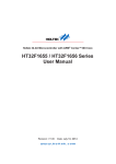
General Installation Manual General Installation Manual for SANYO HIT Photovoltaic Modules. Please read this manual completely before installation or use of SANYO modules. This manual applies to the following products: HIP-200BA3, HIP-195BA3, HIP-190BA3, HIP-186BA3, HIP-180BA3, HIP-175BA3 HIP-200BA5, HIP-195BA5, HIP-190BA5, HIP-186BA5, HIP-180BA5 INTRODUCTION Thank you for choosing SANYO HIT* Photovoltaic (PV) modules. With proper operation and maintenance, SANYO HIT PV modules will provide you with clean, renewable solar electricity for many years. This manual contains important installation, maintenance and safety information. The word “module” as used in this manual refers to one or more PV modules. Retain this manual for future reference. Disclaimer of Liability SANYO does not assume responsibility and expressly disclaims liability for loss, damage, or expense arising out of, or in any way connected with installation, operation, use, or maintenance by using this manual. SANYO assumes no responsibility for any infringement of patents or other rights of third parties which may result from use of modules. No license is granted by implication or under any patent or patent rights. The information in this manual is believed to be reliable, but does not constitute an expressed and/or implied warranty. SANYO reserves the right to make changes to the product, specifications, or manual without prior notice. General Information The installation of solar modules requires a great degree of skill and should only be performed by a qualified licensed professional, including, without limitation, licensed contractors and licensed electricians. ! ! ■ All WARNING instructions should be read and understood before attempting to install, wire, operate, and maintain the photovoltaic module. Contact with electrically active parts of the module such as terminals can result in burns, sparks, and lethal shock whether the module is connected or disconnected. ■ The installer assumes the risk of all injury that might occur during installation, including, without limitation, the risk of electric shock. ■ PV modules generate DC electrical energy when exposed to sunlight or other light sources. Although single modules produce only a low voltage and current, shocks and burns are still a potential hazard. ■ To avoid the hazard of electric shock and injury, cover all of the front surface of the PV modules with a dense, opaque material such as the cardboard box, during installation and handling of the modules. ■ The shock hazard increases as modules are connected in parallel producing higher current. The shock hazard increases as modules are connected in series producing higher voltages. ■ To avoid the hazard of electric shock, work only under dry conditions, with dry modules and tools. ■ Do not stand or step on a module to avoid the hazard of injury and damage to a module. ■ Do not puncture or damage the back-sheet of a module, to avoid the hazard of electric shock and fire. ■ To avoid the hazard of electric shock and injury, children and unauthorized persons should not be allowed near the installation of PV modules. ■ To avoid the hazard of electric shock and injury, be sure to completely ground all modules. ■ To avoid the hazard of electric shock, fire, and injury, do not disassemble the module, or remove any part installed by the manufacturer. ■ Unauthorized persons--except the qualified licensed professional-should not open the cover of the junction box to avoid the hazard of electric shock. Provide suitable guards to prevent yourself from direct contact with 30 VDC or greater to avoid the hazard of electric shock or injury. 1 ■ When carrying a module, two or more people should carry it by its frame and wear non-slip gloves (to avoid injury by a slipping module, to a foot, or cuts by the edge of a frame, and so on). ■ Do not carry a module by its wires or junction box, to avoid the hazard of electric shock, injury or damage to the module. ■ Do not drop anything on the surfaces of a module, to avoid the hazard of electric shock, injury, and damage. ■ To avoid the hazard of electric shock and fire, be sure that all other system components are compatible, and they do not subject the module to mechanical or electrical hazards. ■ Since sparks may occur, do not install the module where flammable gases or vapors are present. ■ Never leave a module unsupported or unsecured. ■ Do not drop a module. ■ Do not use or install broken modules to avoid the hazard of fire, electric shock, and injury. ■ Do not artificially concentrate sunlight on a module to avoid the hazard of fire or damage. ■ Do not touch the junction box terminals to avoid the hazard of electric shock and injury. ■ Do not change the wiring of bypass diodes to avoid the hazard of electric shock and injury. ! ! CAUTIONS ■ Use a module for its intended purpose only. ■ Do not treat the back sheet and front surface with paint or adhesives to avoid reducing its’ functionality, damage, inoperable conditions, and other unknown troubles. © December 2005 Sanyo Electric Co., Ltd. All Rights Reserved GENERAL SAFETY Follow all permission, installation and inspection requirements. Before installing modules, contact the appropriate authorities to determine permissions, installation, and inspection requirements which should be followed. ● Electrically ground modules for all systems of any voltage. If not otherwise specified, it is recommended that requirements of the latest National Electrical Code (USA) or Canadian Electric Code (Canada) or other national or international electrical standards be used. ● Be sure that the construction or structure (roof, façade, etc.) where the modules are being installed, has enough strength. For modules mounted on roofs, special construction or structures may be required to help provide proper installation. Both roof construction and module installation design have an effect on the fire resistance of a building. Improper installation may contribute to fire hazards. Additional devices such as ground fault, fuses, and disconnects may be required. ● Do not use modules of different · specifications in the same system. ● Follow all safety precautions of other system components used. ● UL Listing Information: To satisfy UL requirements, when installing the modules, be sure to: Use only stranded or solid copper single –conductor type UF cable or USE cable, rated sunlight resistant, for modules and interconnect wiring that is exposed to weather. 2) Observe the requirements described in sections labeled INSTALLTION and SPECIFICATIONS. 3) Grounding of the module frame is required. When ground wires greater than 6mm2 (No.10 AWG) are required, the installer will need to provide suitable terminal connectors. The appropriate material should be used for mounting hardware to prevent the module frame, mounting structure, and hardware itself from corrosion. ● Install modules where they are not shaded by obstacles like buildings and trees. Especially pay attention to avoid partially shading the modules by objects during the daytime. ● Please contact your SANYO authorized representative with questions regarding mounting profiles for modules. ● Notes on Installation Clearance between the module frame and the mounting surface is required to allow cooling air to circulate around the back of the module. This also allows any condensation or moisture to dissipate. The module should never be sealed to the mounting surface with sealant that prevents air from circulating under the module. ● To satisfy the UL fire class C rating for the modules, the recommended standoff height is 4 inches minimum. If other mounting methods are used, this may effect the fire class rating. ● Standard Operating Condition SANYO recommends that modules be operated under Standard Operating Conditions (SOC). An installation location with conditions beyond SOC or with other Special Conditions (see below) should be avoided. SOC of SANYO modules is as follows: 1. Standard Operating Conditions (1) The modules should be operated only in terrestrial applications. No space or other Special Conditions (see below). (2) The ambient temperature should be within –20℃ (-4°F) to 40℃ (104°F). (3) The relative humidity should be within 45% to 95%. (4)The installation place should be less than 1,000m (3,280ft) above sea level. Installations more than 1,000m (3,280ft) are allowed only if the wind pressure load for a module is less than 2,170N/m 2 (45PSF). 2. Special Conditions (1) The ambient temperature and installation place are different from SOC. (2) The salt damage is heavy at the installation place. (3) The hail and snow damage is heavy at the installation place. (4) The sand and dust damage is heavy at the installation place. (5) The air pollution, chemically active vapors, acid rain, and/or soot, etc. are heavy at the installation place. Installation (reference) 1) This referential figure is for HIP-xxxBA3 modules. Solar Module f8 14 27 27 Metal fitting (4 places) Mounting Structure Rail INSTALLATION Metal fitting Solar Module General ● Please read this guide completely before installation or use of the modules. This section contains electrical and mechanical specifications needed before using your SANYO PV modules. ● Modules should be firmly fixed in place in a manner suitable to withstand all expected loads, including wind and snow loads. ● Do not drill additional mounting holes in the module frames, as it will void the warranty. M6 Nut Spring washer Flat washer Metal fitting Mounting Structure Rail Module M6 Bolt/setscrew Mounting Structure Rail Between Modules End of Module Figure 1. Installation 2 SPECIFICATIONS WIRING Notes on Specification General (1) Rated electrical characteristics are within 10% of the values measured at Standard Test Conditions (STC). STC are: Irradiance of 1000W/m, 25℃ cell temperature, and solar spectral irradiance per IEC 60904-3. Earth Ground Wiring All wiring should be done in accordance with applicable electrical codes. Wiring methods should be in accordance with the NEC in USA or CEC in Canada. • All wiring should be done by a qualified, licensed professional. Grounding should be carried out by the securement to the module or array frame to avoid the hazards of electric shock or fire. The array frame shall be grounded in accordance with NEC Article 250 (USA) or CEC in Canada. Each framed module has a hole in the shorter side frame rail, to connect a grounding conductor to the module metal frame (see Figure 2). Mechanical / Electrical Specifications Electrical Specification Model Cell Number in Series Rated Pow er, Watts (Pmax) Maximum Pow er Voltage (Vpm) Maximum Pow er Current (Ipm) Open Circuit Voltage (Voc) Short Circuit Current (Isc) Cell Type Maximum System Voltage (Voc) Factory Installed Bypass Diodes Mechanical Specification Model Length, mm (inches) Width, mm (inches) Frame Depth , mm (inches) Weight, kg (pounds) HIP-200BA3 HIP-195BA3 HIP-190BA3 HIP-186BA3 HIP-180BA3 HIP-175BA3 HIP-200BA5 HIP-195BA5 HIP-190BA5 HIP-186BA5 HIP-180BA5 96 96 96 96 96 96 96 96 96 96 96 200 195 190 186 180 175 200 195 190 186 180 55.8 55.3 54.8 54.4 54.0 52.9 55.8 55.3 54.8 54.4 54 3.59 3.53 3.47 3.42 3.33 3.31 3.59 3.53 3.47 3.42 3.33 68.7 68.1 67.5 67.0 66.4 65.7 68.7 68.1 67.5 67.0 66.4 3.83 3.79 3.75 3.71 3.65 3.64 3.83 3.79 3.75 3.71 3.65 HIT* HIT* HIT* HIT* HIT* HIT* HIT* HIT* HIT* HIT* HIT* 600 600 600 600 600 600 600 600 600 600 600 4 4 4 4 4 4 4 4 4 4 4 HIP-200BA3 HIP-195BA3 HIP-190BA3 HIP-186BA3 HIP-180BA3 HIP-175BA3 HIP-200BA5 HIP-195BA5 HIP-190BA5 HIP-186BA5 HIP-180BA5 1319 (51.9) 894 (35.2) 60(2.4) 35 (1.4) 14 (30.9) *HIT = Hetero junction with Intrinsic Thin-layer Ground Location (1 place) (2) The current output for the modules shown in the Specifications is measured at Standard Test Conditions. These conditions may not be frequently observed in actual practice. (3) Under normal conditions, a photovoltaic module may experience conditions that produce more current and/or voltage than reported at standard component test conditions. Accordingly, the values of Isc and Voc marked on UL listed modules should be multiplied by a factor of 1.25 when determining voltage ratings, conductor capacities, fuse sizes, and size of controls connected to the module output. USA: Refer to Section 690-8 of the U.S. National Electrical Code for an additional multiplying factor of 1.25 which may be applicable. Mechanical Loading The modules should be mounted at the four quarter points by the means shown in Figure 3.1 and 3.2. This method offers a maximum loading of 2170N/m2 (45PSF, in a static state) on the module surface. Wiring should be protected to help ensure personal safety and to prevent its damage. All modules connected in series should be of the same model number and/or type. Ground hole Junction Box Label Do not connect modules in parallel without using a connection box. Module Wiring The maximum number of modules that can be wired in series is seven (7). The SANYO solar modules are not designed for “off-grid” or battery charging systems. It is not recommended to use them to charge batteries. These modules contain factory installed bypass diodes. If these modules are incorrectly connected to each other, the bypass diodes, cables, or junction box may be damaged. Array Wiring The term “array” is used to describe the assembly of several modules on a support structure with associated wiring. Use copper wire that is sunlight resistant and is insulated to withstand the maximum possible system open circuit voltage. Check your local codes for requirements. 3 Backside The ground hole is on the inside of the module frame. Figure 2. Module Ground Position Dimensions Models (Standard): HIP-200BA3, HIP-195BA3, HIP-190BA3, HIP-186BA3, HIP-180BA3, HIP-175BA3 Ground (1 place) Dimensions in mm Junction Box Label negative ( - ) positive ( + ) 78cm (30.7in) 63cm (24.8in) Cable Connector (MCTM Plug) Connector MC TM Plug negative ( - ) Mount Locations (4 places) Front Side Backside positive ( + ) Figure 4. Configuration of Junction Box Note:AAmodule module should is installed on a Note: be attached platform a mount with standard setting rangerail on(shaded) or support structure within the shaded range. Section A-A’ Figure 3.1 Standard Model Dimensions DIODES Module Terminations A junction box as a terminal enclosure is equipped for electrical connections on SANYO modules. Modules are equipped with MCTM plugs as a terminal enclosure. Use these MCTM plugs for electrical connections. Please contact your SANYO authorized representative with questions regarding other electrical connections for modules. Bypass Diodes When the modules in series strings are shaded partially, it may cause reverse voltage across cells or modules, because the current from other cells in the same series is forced to flow through the shaded area. This may cause undesirable heating to occur. The use of a diode to bypass the shaded area can minimize both heating and array current reduction. Junction Box and Terminals Modules equipped with one junction box contain terminals for both positive and negative polarity, and bypass diodes. One terminal is dedicated to each polarity (with the polarity symbols engraved onto the body of the junction box ) (see Figure 4). All SANYO modules are equipped with factory installed bypass diodes. The factory installed diodes provide proper circuit protection for the systems within the specified system voltage, so that you do not need any other additional bypass diodes. Contact your authorized SANYO representative for proper diode type, if it is necessary to add or change diodes due to system specifications. Conduit For applications where wire conduits are used, follow the applicable codes for outdoor installation of wires in conduits. Verify that all fittings are properly installed to protect wires against damage and prevent moisture intrusion. 4 Dimensions For More Information, Models (deep-frame): Please Contact HIP-200BA5, SANYO HIP-195BA5, HIP-190BA5, HIP-186BA5, HIP-180BA5 Authorized Representatives Ground (1 place) Dimensions in mm at: www.sanyo.com/industrial/sol ar/representatives.cfm Junction Box Label negative (-) positive ( + ) 78cm (30.7in) 63cm (24.8in) Connector (MCTM Plug) Backside Mount Locations Front Side Note: A module should be installed on a support structure in accordance with the following: Use four (4) symmetrical mounting points within set range A. Section A-A’ Figure 3.2 Deep-Frame Model Dimensions MAINTAINENCE Some maintenance is recommended to maintain optimal output performance of the solar modules. If the module surface becomes dirty, it may reduce output power. It is recommended to clean the surface of the module with water and a soft cloth or sponge. A mild non-abrasive detergent may be applied for persistent dirt. It is also recommended to inspect the module’s electrical and mechanical connections annually. The return of any modules will not be accepted by SANYO unless prior written authorization has been given by SANYO. As part of our policy of continuous improvement SANYO reserves the right to change product specifications at any time without prior notice. If you need electrical and mechanical inspection or maintenance, it is recommended to have an authorized professional carry out the inspection or maintenance to avoid the hazard of electric shock and/or injury. 5 For further information, please contact: