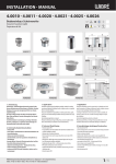
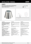
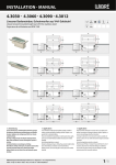
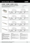
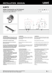
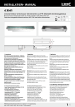
1
Installation · Manual 4.0071 Bodeneinbau-Scheinwerfer mit Einbaugehäuse 67 Ground mounted-Light with built-in pot Projecteur de Sol avec boîtier d‘encastrement V4A Gr. 316L Kabel Cable Câble 2,5 t 115 115 3 95 115 115 65 115 100 115 1. Anwendung Bodeneinbauscheinwerfer geeignet für Markierung, Akzentuierung und Beleuchtung von Gebäuden, Fassaden, Skulpturen, Terrassen oder als allgemeine Effekt- bzw. Orientierungsbeleuchtung. Der Einbau erfolgt im Boden oder Wand für befestigte Flächen, Wege, Plätze und Wände. Passendes Einbaugehäuse im Lieferumfang enthalten. 1. Application Floor ground installation spotlights, suitable for marking, accenting and lighting of buildings, facades, sculptures, patios or as general effect or orientation lighting. They can be installed in the ground/floor or wall for paved surfaces, paths, open spaces and walls. Matching installation housing included in the scope of delivery. 1. Application Projecteurs d‘orientation et pour le monter dans le sol, adaptés pour le balisage, l‘accentuation et l‘éclairage de bâtiments, façades, sculptures, terrasses ou encore en tant qu‘éclairage décoratif ou d‘orientation. Le montage se fait dans le sol ou le mur pour les surfaces consolidées, les chemins, les places et les murs. Le boîtier de montage adapté est compris dans la livraison. Sonderkonstruktionen-/anwendungen auf Anfrage. Special designs/applications on request. Constructions/applications spéciales sur demande. Überrollbar bis 2500 kg. In Fahrspuren, wo gebremst oder beschleunigt wird (horizontale Kräfte) ist der Einbau nicht möglich. Resistant to rolling loads of up to 2500 kg. They cannot be installed in drive lanes, where braking or acceleration occurs (horizontal forces). Résistant jusqu‘à 2500 kg. Le montage n‘est pas possible dans les voies de circulation subissant des forces horizontales (freinage et accélération). 2. Technische Daten/Konstruktion - Scheinwerfer komplett aus V4A-Edelstahl 1.4571 - Schutzart IP67 - Runde oder quadratische Aufsatzblende aus V4A-Edelstahl, H3 mm - mit POW-LED 3 x 1 W 350 mA kaltweiss (6000 K), neutralweiss (4500 K), warmweiss (3000 K), blau; POW-LED 3 x 1 W RGB 350 mA, Niedervolt-Halogen QR-CB51 ES 20 W/35 W/12 V-AC - kardansich schwenkbar - rotationsymmetrische Lichtverteilung bei POW LED weiß 10° und 30° und RGB 10° und 30° und bei Niedervolt-Halogen 36° - Kabelverschraubung PG11, V4A Edelstahl - inklusive Einbaugehäuse aus Kunststoff POM für den Wand- und Bodeneinbau - Lieferung inklusive Leuchtmittel und 3 m Silikonkabel - Konstantstromnetzteil/RGB Controler/Transformator extern - Gewicht: 1,0 kg 2. Technical data/design - Spotlight, entirely made of V4A stainless steel 1.4571 - Protection class IP67 - Round or square attachment cover, made of V4A stainless steel, H3 mm - with POW-LED 3 x 1 W 350 mA cold white (6000 K), neutral white (4500 K), warm white (3000 K), blue; POW-LED 3 x 1 W RGB 350 mA, low voltage halogen QR-CB51 ES 20 W/35 W/12 V-AC - Universally pivotable - Rotationally symmetric light distribution with POW LED white 10° and 30° and RGB 10° and 30° and for low-voltage halogen 36° - Cable screw fixture PG11, V4A stainless steel - including installation housing made of POM plastic for wall and floor installation - Supplied with lamp and 3 m of silicon cable - Constant-current power source/RGB controller/external transform - Weight: 1,0 kg 2. Caractéristiques techniques/Construction - Projecteur complet en acier inoxydable V4A 1.4571 - Indice de protection IP67 - Enjoliveur rond ou carré en acier inoxydable V4A, H 3 mm - avec POW-LED 3 x 1 W 350 mA blanc froid (6000K), blanc neutre (4500K), blanc chaud (3000K), bleu; POW-LED 3 x 1 W RVB 350 mA, halogène basse tension QR-CB51 ES 20 W/35 W/12 V CA - pivotant à Cardan - Diffusion de la lumière à symétrie de rotation de 10° et 30° pour POW LED blanche et RVB et de 36° pour halogène basse tension - Presse-étoupe PG11, acier inoxydable V4A - Boîtier d‘encastrement en matière plastique POM pour montage mural et au sol inclus - Ampoule et câbles silicone de 3 m inclus dans la livraison - Bloc d‘alimentation en courant continu/contrôleur RVB/ transformateur externe - Poids: 1,0 kg WIBRE Elektrogeräte Edmund Breuninger GmbH & Co. KG · Liebigstrasse 9 · 74211 Leingarten/Germany Telefon: +49 (0) 7131 9053-0 · Telefax: +49 (0) 7131 9053-19 · E-Mail: [email protected] 1/4 Installation · Manual ø 100 3.1 3.3 3.2 3.4 3. Installation/Montage Zur Installation sind die nationalen Sicherheitsvorschriften zu beachten. Es wird keine Haftung für unsachgemäßen Einsatz oder Montage übernommen. Bei nachträglichen Änderungen an den Leuchten wird keine Haftung übernommen. POW-LED Leuchten müssen immer in Reihenschaltung an entsprechenden Konstantstromnetzteilen (siehe Betriebsgeräte) betrieben werden (350 mA). Die Leuchtengehäuse sind nicht zu demontieren, da zum Schutz die Kabel und POW LED Platine vergossen ist. Montage des Scheinwerfers in Beton, Pflaster, Platten, Holzdielen, Erdreich, Kies, Rasenflächen oder Beete möglich. Da bei Projekten die Bodenverhältnisse und Einbausituation variieren ist keine allgemein gültige Montageanleitung möglich. Die Piktogramme verdeutlichen typische Montagebeispiele. 3.1./3.2. Einbau mittels Kunststoffeinbaugehäuse in Beton, Asphalt, Erde o.ä. 3.3. Einbau mittels Kunststoffeinbaugehäuse in dünnwandige Systeme o.ä. Montage Bei Einbau mit Kunststoffeinbaugehäuse in Beton, Asphalt oder Erde sollte für eine sichere Standfestigkeit der Einbauhülse gegebenenfalls ein Fundament vorgesehen werden und für ausreichende Drainage z.B. durch Kiesauffüllung/Sand gesorgt werden. Gegebenenfalls können die seitlichen Öffnungen am Boden des Einbaugehäuse zur Fixierung oder Ausrichtung eingesetzt werden. 3.2. Bei Einbau mit Kunststoffeinbaugehäuse in Wände oder dünn wandige Systeme sollte mit einem Schneidewerkzeug eine Öffnung von D100 mm vorgesehen werden und das Einbaugehäuse mittels den Haltewinkeln fixiert werden. 3.3. Achtung: Für spätere Montage des Scheinwerfers muss die Ober kante Einbaugehäuse mit der Oberkante Abschlussfläche (z.B. Boden, Fliese, Holz) bündig sein. 3.4. Für gewünschte horizontale bzw. vertikale Ausrichtung der Leuchte ist unbedingt auf eine korrekte Fixierung des Einbaugehäuses und Ausrichtung der Schraublöcher für den späteren Scheinwerfereinbau zu achten. 3.5./3.6. 2/4 3.5 3. Installation/mounting When installing, observe the national safety regulations. We are not liable for any improper use or installation. No liability will be accepted in case of subsequent modification to the lights. POW-LED lights must always be operated in series with appropriate constant-current power sources (see operating devices) (350 mA). The light housings must not be removed, since the cable and POW LED printed circuit board are covered with waterproofing for protection. Installation of the spotlight is possible in concrete, pavement, slabs, wooden floor boards, soil, gravel, lawn or garden beds. Since ground conditions and installation circumstances vary, no general installation instructions can be provided. The icons symbolise typical installation examples. 3.1./3.2. Installation using plastic installation housing in concrete, asphalt, soil, or the like. 3.3. Installation using plastic installation housing in thin-walled systems or the like. Installation For installation with plastic installation housing in concrete, asphalt or soil, a foundation as well as sufficient drainage, e.g. with gravel/sand filling, might be needed for secure stability of the installation sleeve. If necessary, the holes in the bottom of the built-in pot can be used to fix or adjust the spotlight. 3.2. For installation with plastic installation housing in walls or thin-walled systems, an hole d100 mm should be cut with a cutting tool and fixed with the brackets. 3.3. For tightness and later installation of the spotlight, the upper edge of the installation housing must be flush with the upper edge of the top layer surface (e.g. ground, tile, wood). 3.4. To be able to align the light horizontally or vertically, as desired, attention must always be paid to correct fixing of the installation housing and alignment of the screw holes for later spotlight installation. 3.5./3.6. 3.6 3. Installation/Montage Respecter les prescriptions nationales applicables en matière de sécurité. Nous déclinons toute responsabilité pour l’utilisation ou le montage non conforme. De même, nous réfutons toute responsabilité pour les modifi cations réalisées sur les luminaires. Pour leur exploitation, les projecteurs à POW-LED doivent toujours être reliés en série au bloc d‘alimentation en courant continu correspondant (voir blocs d‘alimentation) (350 mA). Ne pas démonter les boîtiers de projecteur, étant donné que les câbles et la platine POW LED sont scellés. Montage du projecteur dans le béton, les pavés, les plaques, les lames de bois, la terre, le gravier, les espaces verts ou les plates-bandes. Étant donné que dans les différents projets, les conditions du sol ainsi que la situation d’intégration varient, nous ne pouvons établir une notice de montage générale. Les pictogrammes expliquent les exemples de montage type. 3.1./3.2. Montage avec boîtier d‘encastrement en plastique dans le béton, l‘asphalte, la terre, entre autres. 3.3. Montage avec boîtier d‘encastrement en plastique dans des constructions à parois fines, entre autres. Montage Lors du montage avec boîtier d‘encastrement en plastique dans le béton, l‘asphalte ou la terre, il est recommandé de prévoir le cas échéant une fondation afin de garantir une bonne stabilité du tube de montage et d‘assurer un drainage suffisant, par ex. par un remplissage de gravier/sable. Le cas échéant, utiliser les trous du fond de pot d’encastrement pour la fixation ou le positionnement. 3.2. Lors du montage avec boîtier d‘encastrement en plastique dans les murs ou les constructions à parois fines prévoir avec des outils de coupe un trou de diamètre. 100 mm et monter le pot d’encastrement avec l’aide de l’étrier de fixation. 3.3 Pour l’étanchéité et le montage a posteriori du projecteur, le bord supérieur du boîtier d‘encastrement doit affleurer avec la surface de finition (p. ex. Le sol, les carreaux, le bois). 3.4. Afin d‘assurer l‘alignement horizontal et vertical souhaité du projecteur, veiller impérativement à une bonne fixation du boîtier d‘encastrement et à un alignement approprié des trous de vis pour le montage ultérieur du projecteur. 3.5./3.6. WIBRE Elektrogeräte Edmund Breuninger GmbH & Co. KG · Liebigstrasse 9 · 74211 Leingarten/Germany Telefon: +49 (0) 7131 9053-0 · Telefax: +49 (0) 7131 9053-19 · E-Mail: [email protected] Installation · Manual + braun – blau + sec – Netzteil Ballast Alimentation Hinweis: Reihenverschaltung bauseits Reference: Serial connection made on site Référence: connexion en série a fairre sur place 3.7 POW-LED 3 x 1 W 350 mA POW-LED 3 x 3 W 700 mA 1 2 MAX braun/brown/brun prim sec blau/blue/bleu max 100 m Achtung: Nur werkseitig angeschlossenes Kabel verwenden. Gewünschte Kabellänge bei Bestellung angeben. Wegen mechanischer Beanspruchung sollte das Kabel zusätzlich in einem Schutzrohr verlegt werden. Der Anschluss des Silikonkabels an das Hauptnetz sollte im Trockenen erfolgen bzw. bei Anschluss direkt im Erdreich sind spezielle Anschlusseinheiten mit Vergussmasse zu verwenden. (z.B. WIBRE Art.Nr. 9.9010.68.16) Einzelanschlussader entsprechend den Vorschriften an den Netz teilen elektrisch anschließen. 3.7. Die maximale Anzahl der Leuchten sind dem Manual des Netzteiles zu entnehmen. 3.8. Montage des Scheinwerfers Die Leuchte in die Einbauhülse einsetzen, ca. 0,5 m Kabel in das Gehäuse einlegen und bis auf Oberkante der Abschlussfläche einschrauben. 4. Anschluß an Netzteile/Anschlußmatrix Scheinwerfer mit POW-LED Einheiten sind nur in Reihe anzu schließen. 3.8. Gegebenenfalls Reihenanschluß in separater Verteilerbox vornehmen, die im Außenbereich zusätzlich mit Vergußmasse gegen Feuchtigkeit schützen. 5. Allgemeine Wartungshinweise - Beim Reinigen darf die Leuchte nicht mit Metall angreifenden Reinigungsmitteln in Berührung kommen. Der Einsatz salzsäurehaltiger Reinigungsmittel an und in der Nähe von Scheinwerfer teilen aus Edelstahl ist in jedem Fall zu unterlassen. - Scheinwerfer und Einbaugehäuse regelmäßig reinigen, um Fremdrostablagerungen zu vermeiden. - Achtung: Keine Hochdruckreiniger verwenden. - Achtung: Strahler vor Einfrieren schützen, gegebenenfalls müssen diese demontiert oder speziell geschützt werden. - Verloren gegangene Schrauben dürfen nur durch Schrauben aus V4A ersetzt werden. - Je nach Beanspruchung (Höhe der Watttage, äußere Umstände) ist alle 5–8 Jahre ein Wechsel der Dichtungen (Glasscheibe, Verschraubung, O-Ring) und der Kabel zu empfehlen. Attention: Use only cable connected at the factory. Specify desired cable length when ordering. Because of mechanical load, the cable should also be laid in a protective tube. The silicone cable should be connected to the mains supply under dry conditions, or special connection units with sealing compound are to be used if connected in the soil. (e.g. WIBRE article no. 9.9010.68.16) 3.8 Attention: utiliser uniquement les câbles raccordés en usine. Indiquer la longueur de câble souhaitée lors de la commande. En cas de sollicitation mécanique, le câble doit être posé dans une gaine de protection. Le raccordement du câble en silicone au secteur doit être réalisé en milieu sec et, dans le cas d‘un raccordement direct dans le sol, il convient d’utiliser des unités de raccordement spéciales à masse de scellement. (par ex. WIBRE Réf. 9.9010.68.16) Electrically connect individual wires to the power supply according to regulations. 3.7. The maximum number of lights can be taken from the power supply manual 3.8. Raccorder les différents conducteurs aux blocs d‘alimentation conformément aux prescriptions. 3.7. Le nombre maximal de projecteurs pouvant être reliés est indiqué dans le manuel du bloc d‘alimentation 3.8. Fixing of the Spotlight Place the light into the installation sleeve, insert approx. 0.5 m of cable into the housing, and tighten the screws until the housing is flush with the top edge of the final surface. Fixation du Projecteur Mettre le projecteur en place dans le tube de montage, placer env. 0,5 m de câble dans le boîtier et le visser jusqu‘à affleurement avec la surface de finition. 4. Connection to power units/ connection matrix Spotlights with POW-LED units may only be connected in series. 3.8. If necessary. make the serial connection in a separate distribution box, which outside must also be protected against moisture with sealing compound. 4. Raccordement aux blocs d‘alimentation/ Matrice de raccordement Les projecteurs à POW-LED doivent uniquement être raccordés en série. 3.8. Le cas échéant, procéder au raccordement en série dans des boîtiers répartiteurs séparés dont l‘extérieur doit en outre être protégé contre l‘humidité à l‘aide d‘une masse de scellement. 5. General service information - When cleaning, make sure that the lights do not come into contact with metal-corroding cleaning agents. The use of cleaning agents containing hydrochloric acid on and near spotlight parts made of stainless steel must always be avoided. - Clean spotlights and installation housing regularly to avoid extraneous rust deposits. - Attention: Do not use high-pressure cleaners. - Attention: Protect lightbulbs from freezing; they must be removed, if necessary, or specially protected. - Lost screws may only be replaced by screws made of V4A. - Depending on load (wattage, external conditions), we recommend changing the seals (on the glass pane, screws, O-ring) and cable every 5–8 years. 5. Instructions d‘entretien générales - Lors du nettoyage, le projecteur ne doit pas entrer en contact avec des détergents agressifs contre les métaux. L‘utilisation de détergent à base d‘acide chlorhydrique sur et à proximité des pièces du projecteur en acier inoxydable est totalement interdite. - Nettoyer régulièrement le projecteur et le boîtier de montage afin d‘éviter tout dépôt d‘oxydation. - Attention: ne pas utiliser de nettoyeur haute pression. - Attention: Protéger les projecteurs contre le gel ; le cas échéant, les démonter ou assurer une protection spéciale. - Les vis perdues ne doivent être remplacées que par des vis en acier inoxydable V4A. - Selon la sollicitation (puissance, circonstances environnementales), il est recommandé de procéder au changement des joints (sur les vitres, les raccords vissés et les joints toriques) et du câble tous les 5 à 8 ans. WIBRE Elektrogeräte Edmund Breuninger GmbH & Co. KG · Liebigstrasse 9 · 74211 Leingarten/Germany Telefon: +49 (0) 7131 9053-0 · Telefax: +49 (0) 7131 9053-19 · E-Mail: [email protected] 3/4 Installation · Manual 6. Garantiebestimmungen Folgende Garantiezeiten und Bestimmungen gelten vom Tage der Lieferung an: - 24 Monate auf WIBRE-Scheinwerfer. - Von den Garantieansprüchen ausgenommen sind Leuchtmittel - Unter die Garantie fallen nachweisbare Material-, Konstruktionsund Verarbeitungsfehler vonseiten des Herstellers. - Für Schäden, welche durch Nichtbeachtung dieser Betriebs anleitung, oder durch unsachgemäße Reparatur entstehen, können wir keine Garantie übernehmen. - Keine Garantie besteht, wenn die Installation nicht korrekt nach den Bestimmungen vorgenommen wurde oder bei Verwendung nicht geeigneter Leuchtmittel bzw. Anschlusskabel. - Änderungen, die dem technischen Fortschritt dienen, behalten wir uns vor. Artikelnummer Article Number Numéro d‘article runde Blende circular cover enjoliveur rond quadratische Blende squared cover enjoliveur carré 4.0071.20.01 4.0071.40.01 6. Warranty conditions The following warranty periods and conditions apply from the day of delivery: - 24 months on WIBRE spotlights. - Lamps are excluded from warranty claims. - The warranty covers verifiable material, design and work errors by the manufacturer. - We cannot accept liability for damages caused by failure to comply with this operating manual or through improper repair. - The warranty is void if the installation was not performed properly according to the instructions or unsuitable lamps or connecting cables are used. - We reserve the right to make changes for the purpose of technical progress. 6. Conditions de garantie Les délais et dispositions de garantie suivantes s‘appliquent à compter de la date de livraison : - 24 mois sur le projecteur WIBRE. - Sont exclus des conditions de garantie les ampoules. • La garantie couvre les défauts de matériaux, les vices de construction et de traitement dont la preuve est apportée qu‘ils sont imputables au fabricant. • Les dommages, résultant du non-respect de la présente notice d‘utilisation ou d‘une réparation non conforme, sont exclus de la garantie. • Nous déclinons toute garantie dans les cas où l‘installation n‘a pas été effectuée dans les règles de l‘art selon les instructions ou lors de l‘utilisation d‘ampoules ou de câbles de raccordement non appropriés. • Nous nous réservons le droit de réaliser toute modification répondant au progrès technique. Leuchtmittel Lamps Source Leistung Wattage Puissance Konstantstrom Constant current Courant Ausstrahlwinkel Radation Angle Angle de rayon POW-LED kaltweiß cold white blanc froid 6000 K 3 x 1 W (100lm/LED at 350mA) 350mA spot 10° 4.0071.20.02 4.0071.40.02 POW-LED warmweiß warm white blanc chaud 3000 K 3 x 1 W (80lm/LED at 350mA) 350mA spot 10° 4.0071.20.03 4.0071.40.03 POW-LED neutralweiß neutral white blanc neutre 4500 K 3 x 1 W (90lm/LED at 350mA) 350mA spot 10° 4.0071.20.06 4.0071.40.06 POW-LED blau blue bleu 3 x 1 W (400mW/LED at 350mA) 350mA spot 10° 4.0071.20.09 4.0071.40.09 POW-LED RGB RVB 3x1W 350mA 10° 4.0071.20.11 4.0071.40.11 POW-LED kaltweiß cold white blanc froid 6000 K 3 x 1 W (100lm/LED at 350mA) 350mA medium 30° 4.0071.20.12 4.0071.40.12 POW-LED warmweiß warm white blanc chaud 3000 K 3 x 1 W (80lm/LED at 350mA) 350mA medium 30° 4.0071.20.13 4.0071.40.13 POW-LED neutralweiß neutral white blanc neutre 4500 K 3 x 1 W (90lm/LED at 350mA) 350mA medium 30° 4.0071.20.16 4.0071.40.16 POW-LED blau blue bleu 3 x 1 W (400mW/LED at 350mA) 350mA medium 30° 4.0071.20.19 4.0071.40.19 POW-LED RGB RVB 3x1W 350mA 30° 4.0071.20.20 4.0071.40.20 QR-CB51 ES 20W (1000 cd) 12V-AC 36° 4.0071.20.35 4.0071.40.35 QR-CB51 ES 35W (2200 cd) 12V-AC 36° Netzteil · Power supply · Alimentation Beschreibung Description 5.0635.00.03 Netzteil Power Supply Alimentation für for pour 3 x POW-LED 1 W monochrom Input: 220–240 V; Output: 350 mA; 12 V-DC; IP20 0,1 kg 5.0635.00.10 Netzteil Power Supply Alimentation für for pour 6 x POW-LED 1 W monochrom Input: 220–240 V; Output: 350 mA; 24 V-DC; IP20 0,1 kg 5.0635.00.20 Netzteil Power Supply Alimentation für for pour 12 x POW-LED 1 W monochrom Input: 220–240 V; Output: 350 mA; 48 V-DC; IP20 0,1 kg 5.0635.09.16 Controler Commandes für for pour max. 12 POW LED 1 W RGB Input: 220–240 V; Output: 350 mA, max.12 V-DC, max. 12 W; IP65; 0,3 kg 5.0635.09.50 Controler Commandes für for pour max. 36 POW LED 1 W RGB Input: 220–240 V; Output: 350 mA, max.48 V-DC, max. 36 W; IP65; 0,5 kg 5.0098.00.00 Transformator Transformer Transformateur für for pour 1 x 50 W Input: 220–240 V; Output: 50 VA; 1 In/1 Out; 12 V-AC; IP65; 2,4 kg W267 Artikelnummer Article Number Numéro d‘article 4/4 WIBRE Elektrogeräte Edmund Breuninger GmbH & Co. KG · Liebigstrasse 9 · 74211 Leingarten/Germany Telefon: +49 (0) 7131 9053-0 · Telefax: +49 (0) 7131 9053-19 · E-Mail: [email protected]