1
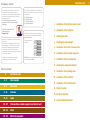
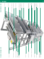
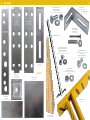
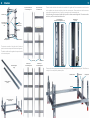
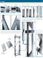
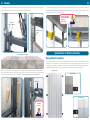
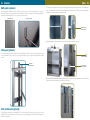
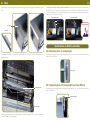
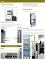
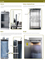
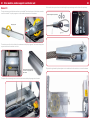
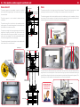
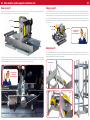
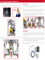
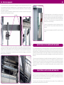
Installation manual
for SKG service lifts
Installation order
Preliminary remarks
The existing shaft dimensions need to be
checked for conformity with the layout
drawings. In case of deviations, please make
a technical clearification with us before the
installation process.
The installation must be made in
compliance with the relevant safety
standards.
Don‘t stand underneath the
unsecured cabin.
Danger of life!
This installation manual is a recommendation
based on our experience, it is not a working
instruction.
Please take the installation details from our
layout drawings. Front side, which is side X
on the layout drawings, always means the
side on which the machine room door is
positioned. Please install along the described
order in this manual.
Deviations to these photos are always
possible due to technical variations.
The controller is delivered in a separate box.
Next to this installation manual, you will also
find in the box:
A Wiring diagrams
B Capacity signs
C Operation manual
D Layout drawings
1.
Installation of the bottom structure part
2. Installation of the safety bar
All bolted connections need to be fastened
with the torques as mentioned in the table:
strength class 8.8
3. Inserting the cabin
Fastening torques of
all screws
4. Inserting the counterweight
M4
5 Nm
M5
7,1 Nm
M8
30 Nm
M6
M 10
M 12
12 Nm
60 Nm
105 Nm
Exception: the round-head screws M 8 need
to be fastened to 25 Nm.
5. Installation of the other structure parts
6. Installation of the machine supporter
7. Installation of the drive machine
8. Inserting the suspension elements
Table of contents
3
Installation order
4-5
View example
6-7
Accessories
8 - 14
Structure
15 - 21
Cabin
22 - 29
Drive machine, machine supporter and divertor unit
30 - 32
Doors
33 - 35
Electrical components
9. Installation of the landing doors
10. Installation of the controller
11. Installation of the shaft electrics
12. Check of overrun
13. Put lift in operation
14. Security-related final check
3
Safety bar
Structure diagonal
Bottom structure part
Guide rail
Trailing cable
Counterweight with weight inserts
Safety bolt on weight
Structure strap
Guide rail
Ropes
Top part of structure
Machine room lightning
Protective grid on sheave
Drive machine
Counterweight side
Structure strap
Bi-parting door
Safety bar
Emergency stop switch
Push button element
Structure strap
Cabin
Structure diagonal
Electrical bridge
Structure strap
Bi-parting door
Emergency release key
Push button element
Structure strap
Pulley supporter
Double hinged machine room door
Main switch
Controller
Installation side
4
View example
5
6
Accessories
7
Foot brackets
for structure fixing to ground
Hexagon bolts M 10x30
Contact washers A 10,2
Hexagon bolts M 10
for machine supporter and drive machine
Locking plate
for guide rail
160 x 48,5 x 2 mm
Wall anchors 90° folded
85 x 55 x 35 x 3 mm
Connection piece
for guide rail
160 x 45 x 3 mm
Woodscrews 8x70
PVC-dowels S 12
Washers A 8,4
for structure fixing
Structure bracket
215 x 35 x 3 mm
Emergency release key
Self-locking nuts M 8x16
Round-head screws M 8x16
Washers A 8,4 DIN 9021
for structure straps / brackets
diagonals / foot brackets / wall anchors
Hexagon screws M 8x20
for structure brackets / structure straps
and guide rails
Washers A 8,4 DIN 125
for structure brackets
Straight wall
anchor
135 x 35 x 3 mm
Clamp plates
for structure straps
50 x 50 x 3 mm
Hexagon nut M 8
Contact washers A 8,2
for structure brackets / structure straps
and guide rails
Scale 1:1
Balance plate
90 x 90 mm
Metal plate
for guide rail
100 x 40 x 1,25 mm
Safety bar GV 36
with chain
Wooden wedges
as installation support
8
Structure
9
Top part of structure part
on counterweight side
Top part of structure
on installation side
Structure straps
Left structure part
on counterweight
side
Please consider that the cabin needs to be inserted in the guide rails. We recommend to insert the cabin
with a suitable hoist after the installation of the first structure parts. Please make sure that the structure
parts with the elongated hole row (U-profile) is mounted on the counterweight side.
In the following, the structure side with the U-profile is called counterweight side. The structure side
with the L-profile is called installation side.
Counterweight side
(U-profile with elongated hole row)
Right
structure part on
installation side
Installation side
(L-profile)
Structure
diagonal
Bottom
structure part
Structure strap
The structure consists of the right and left structure
parts, the structure straps and the structure diagonals.
The cable conduits and the guide rails are pre-installed
on the structure parts.
Guide rails
Structure diagonal
(long)
Structure part
on counterweight side
Cable conduit
Structure part
on counterweight side
Please adjust the support points before positioning the bottom, red painted structure parts. The difference
in height is to be adjusted by balance plates.
Structure bracket
Structure diagonal
(short)
Guide rail
Bottom structure part
(red painted)
Metal plate
Locking plate
10
Structure
11
The structure straps are to be screwed together with the structure parts as shown on the photos.
Counterweight side
Installation side
Sliding brackets are pre-installed on top of the structure parts. These serve as additional structure brackets
for the further fixing of the structure parts.
Structure bracket
Pre-installed
sliding bracket
Misplaced
sliding bracket
Each structure part with 2 m length is to be reinfored with a structure diagonal.
The sliding bracket is to be inserted into the end of the guide rail. This facilitates the alignment of the guide
rails. The guide rail ends are to be screwed together with 2 connection pieces. These screws should be
tightened after the alignment of the guide rails.
Metal
sheet
The safety bars are to be installed with 2 pieces M 6 screws on the bottom structure part guide rails. This
kind of safety bar is available only when the cabin is not equipped with buffers. The narrow safety bar is to
be fixed on the counterweight side (U-profile), the wide safety bar on the installation side (L-profile).
Before the installation of the top
structure part, the counterweight
must be inserted in the U-profile.
Sliding bracket
(wide) safety bar
on the installation side
Counterweight
Guide rail
Structure
bracket
2 connection pieces
(narrow) safety bar
on the counterweight side
U-profile
12
Structure
13
The counterweight is adjustable between the guides. Unscrew the screws of the frame for inserting the
counterweight inserts. After inserting, the screws must be tightened again.
The safety bar (yellow) is to be fixed on the structure with the chain. On all works in the shaft, the safety
bar must be put in the structure between 5 to 25 mm next to the guide rail at a minimum height of 1,8 m
for blocking the cabin and the counterweight.
Put in the safety bar on
all shaft works correctly.
Otherwise:
Danger of life!
Adjustment
of the counterweight
Safety bolt weight
Special features on different constructions
Insert the weight inserts in a zigzag
Rear guard plates (optional)
When the complete structure is installed, it is to be plumb adjusted with the wooden wedges and then fixed
securely with the wall anchors, dowels and screws. The screw joint in the brickwood only serves for the
fixing of the spacers (wall anchor and foot bracket). The screws must not be loaded on strain.
The rear guard plates are to be screwed together with the structure straps on the opposite side of the
landing doors. On through-car lift cabins, they prevent that the goods projecting the shaft structure. The
rear guard plates need to be installed at the same time as the the structure straps. When installing the rear
guard plates retrospectively, the stucture straps must be removed from the rear guard plates.
Rear guard plates
Rear guard plates
Wall anchor
Counterweight side
You must load
the screws
on strain!
14
Structure
Cabin
Baffle plates (optional)
The baffle plates (optional) are to be installed on the structure to the full travel height. As a support, 2
brackets are bent, so the baffle plates can be hooked on the structure straps. Then the baffle plates are
screwed with the drilling bolts ø 4,2 x 16 onto the structure straps.
Baffle plate sheet
15
The cabin is pre-installed. It needs to be inserted with a suitable hoist into the guide rails. The cabin guide
shoes can be adjusted inside the holding brackets with the M 10 screws. The retiring cam for opening the
landing doors is positioned on the installation side.
Bending the bracket
Cam for opening
the landing doors
Only on 2 stops, a further control cam for the floor switches is installed at the side.
Safety gear (optional)
On lifts with safety gear, the guide rails are made of blank steel. On this construction, the alignment sheets
are not applicable. There is no need for the balance weight. A govenor tension weight will be installed
instead.
Guide rails
made of blank steel
Cam
for the floor switches
Cam for opening
the landing doors
Only on lifts with more than 2 stops, a holding metal sheet with adjustable magnets is used. The holding
metal sheet with the magnets replaces the floor switch cam.
Shaft partition wall (optional)
A shaft partition wall needs to be installed if 2 lift units are sharing a common shaft. Only then, a shaft
partition wall is delivered with the lift. You can see on the layout drawings to which lift unit the shaft partition
wall has been packed.
16
Cabin
17
The cabin apron is to be fixed with the round-head screws to the lower cabin stripe (not applicable on cabin
door).
The riding on the cabin ceiling is strictly forbidden! You are only allowed to step onto the cabin ceiling
(see EN81-3 0.3.12.1). Therefore, the safety rope on the cabin must be put around the guide rail and must
be secured with the shackle. The electrical bridge next to the emergency stop switch will be opened when
necessarily so the safety circuit is open.
Closed electrical bridge
Electrical
bidge
Opened electrical bridge
Safety rope
Shackle
Riding forbidden!
Cabin stripe
Cabin apron
Special features on different constructions
ISO-A (Bi-parting doors on serving height)
The trainling cable fixing is to be installed center the cabin and then to be fixed with clamp plates to the
stripes at the side.
The landing doors will be unlocked by a fixed type cam. There are 2 types of door locks without fail safety
device: TV90 and TV3074.
Fixed type cam
ISO-C (Bi-parting doors with serving height lower than 700 mm)
Trailing cable fixing
Clamp plates
The landing doors will be operated by an electrical retiring cam (EMT 15). The door lock with fail safety
device is called TV90a.
Electrical retiring cam
Trailing cable
A trailing cable is applicable only if safety switches or electrical retiring cams (EMT14 or 15) are installed on
the cabin. Please see wiring diagrams.
18
Cabin
19
ISO-D (Swing doors serving at floor level)
Heated cabin shelf, cabin floor or cabin ceiling
The landing doors will be operated by an electrical retiring cam (EMT 14).
Heated cabin shelves are screwed inside the cabin ceiling and can not be taken out. The switch / switches
for switching on or off the heater is / are located at the front of the cabin ceiling.
Special angles for cabin shelf
In this design, the cabin is equipped with several angles for trays.
Drive machine with chain wheel or rope drum
The cabin is equipped with an additional switch activation cam for the control current limit switch. The
additional safety switch is activated automatically if the floor limit switch fails. The position (left or right) of
the control current limit switch depends on the cabin depth.
Cabin roller shutter
The cabin roller shutter is pre-installed and its tension is pre-adjusted. During the installation of the roller
shutter, the proper closing and the function of the switch need to be checked. The roller shutter switch
is positioned underneath the cover of the tension device. The tension of the roller shutter spring can be
adjusted at the side. Hold the spring at first, then loose the tension screws.
Tension device
Switch activated
Activation cam
for control current limit switch
Activation cam
for floor switch
Activation cam
for control current
limit switch
Special features on different constructions
Cabin shelf
The cabin shelves need to be layed on the plastic rings in the cabin to prevent any
slipping.
Tension screws
Spring
20
Cabin
21
Cabin door
Fixed-type or hinged-type lattice gate
The cabin door is to be fixed with the M 6 x 16 screws to the cabin. During the installation of the cabin door,
the proper closing and the function of the switch needs to be checked. The car door switch is positioned on
top of the cabin.
The lattice gates are pre-installed and pre-adjusted. During the installation of the lattice gate, the proper
closing and the function of the switch need to be checked.
Car door switch
Lattice gate switch
Drop bar
Cabin light
The drop bar is pre-installed and pre-adjusted. During the installation of the drop bar, the proper closing and
the function of the switch needs to be checked. The drop bar switch is positioned at the outside of the cabin
behind the opening of the drop bar in closed position.
The lamp is mechanically pre-installed. For wiring, please see the wiring diagrams.
Drop bar switch
Drop bar
in closed position
22
Drive machine, machine supporter and divertor unit
23
On the cabin, the ropes are then to be led through the rope anchorages and be fixed with rope clamps.
Sheave 1:1
The top structure part with the drive machine is pre-installed. The advised torques of the bolted connection
need to be checked. The pulley supporter is to be installed in between the 2 crossbeams
Rope anchorages and rope clamps
Rope rocker
Pulley supporter
The machine room floor is to be fixed to the crossbeam and the pulley supporter. The needed clamp plates
are pre-installed on the machine room floor.
These pictures show the machine
room floor on a lift type with cabin
roller shutter.
The ropes of the counterweight are to be led over the sheave and the pulley supporter to the cabin.
The protective grid made of perforate plate is to be installed on the drive machine so to cover the sheave.
24
Drive machine, machine supporter and divertor unit
Sheave drive 2:1
25
Chain
Drive machine
The machine supporter is pre-installed. It needs to be installed
center on the buffer support angles. The sheave needs to be front,
the motor behind.
Rope anchorage
machine supporter
The machine room floor is to be layed on top of the crossbeam. There are 2 chain openings and 1 cable
opening in the machine room floor. The drillings on the crossbeam need to be made on site.
The machine supporter with the chain deflector need to be installed center on the crossbeam of the top
structure part. The drive machine is to be fixed on the machine supporter. The chains are to be led from the
balance weight over the small chain wheels and the drive machine to the cabin.
The pulley supporter is to be installed in between the two
crossbeams.
The machine room floor is to be fixed on the crossbeam and the
pulley supporter. The needed clamp plates for this installation are
pre-installed on the machine room floor.
Chain deflector
The ropes are running from the rope anchorages on the machine
supporter to the pulley on the cabin. The rope then runs to the
drive machine where the ropes are splitted, one rope on each
pulley on the counterweight. From the counterweight the ropes
run to the anchorages above the counterweight.
Drive machine
Pulley cabin
Machine supporter
The protective grid made of perforate plate is to be installed on the
drive machine so to cover the sheave.
Holding bracket
for chain cover
Protective grid
Rope anchorage above the counterweight
Drive machine
The chains are to be fixed with chain locks at their ends. The chain rocker on the cabin and the balance
weight must be in a horizontal position. If the chains are too long, they need to be shortened with an angle
grinder. Before cutting the chains, the rivet heads need to be grinded down (Wear protective glasses!). The
protective grid is to be installed on the drive machine so to cover the chain wheels.
Machine room from underneath
Optional:
overload contact
The chain rocker on the
cabin and the balance
weight must be in a
horizontal position.
Counterweight
Chain rocker
26
Drive machine, machine supporter and divertor unit
27
Drum on top 1:1
Drum on top 2:1
The machine supporter is pre-installed. It needs to be installed center on the buffer supporter angles. The
drive machine needs to be in front position, the motor in back position.
The machine supporter is pre-installed. It needs to be installed center on the buffer supporter angles.The
drive machine needs to be in front position, the motor in back position. The ropes are to be led from the
machine supporter on the cabin, then under the pulley and back to the machine supporter. The ropes are to
be led through the rope anchorages on the machine supporter and fixed with rope clamps. Please ensure
that the rope rocker is in a horizontal position because the slack rope switch must not be activated by the
switch cam.
Motor behind
Motor behind
Drum front
Rope rocker
Drum front
The rope rocker
must be in a
horizontal position!
Drum below 1:1
The ropes are to be led from the machine supporter to the cabin. Then the ropes are to be led through
the rope anchorages und fixed with the rope clamps. Please ensure that the rope rocker is in a horizontal
position because the slack rope switch must not be activated by the switch cam.
The pulley supporter is to be screwed together with the crossbeam. The aluminium rings Ø 30 mm x 20
mm are serving as spacers between the pulley supporter and the crossbeam. The drive machine is to be
screwed together with the machine supporter.
Pulley supporter
The rope rocker
must be in a
horizontal position!
Slack rope switch
Switch cam
Spacer
28
Drive machine, machine supporter and divertor unit
The ropes are to be held on the top over both pulleys to the cabin. On the cabin, they are to be led through
the rope anchorages and fixed with rope clamps. Please ensure that the rope rocker is in a horizontal
position because the slack rope switch must not be activated by the switch cam.
The rope rocker
must be in a
horizontal position!
29
Drum below 2:1
The pulley supporter is to be screwed together with the crossbeam. The aluminium rings Ø 30 mm x 20 mm
are serving as spacers between the pulley supporter and the crossbeam.
The drive machine with the drum is to be screwed together with the machine supporter. The ropes are to be
led upwards over both pulleys of the pulley supporter to the pulley on the cabin. From there, the ropes are
to be led to the rope rockeron the pulley supporter and are to be fixed with rope anchorages.
The cover for the machine room is to be layed on the L-profiles and fixed with the clamp platess. Under the
rope drum is a contact plate. If the rope is unwinding itself from the rope drum and touching this plate, the
lift will stop immediately. For wiring, please see the wiring diagrams.
The cover for the machine room is to be layed on the L-profiles and fixed with the clamp plates.
Spacer
Cover
Contact plate (SKT1)
Option overload
Under the rope drum is a contact plate. If the rope is unwinding itself from the rope drum and touching this
plate, the lift will stop immediately. For wiring, please see the wiring diagrams.
The overload device consists of a stretch measuring instrument (DMS) and the measurement amplifier. The
measurement amplifier is installed in a cable box. The cable box is to be clamped vertically on the structure.
The DMS is to be screwed on the described fixing points. The connection cables of DMS and measurement
amplifier are soldered up.
Adjustment: the operable lift unit is to be loadad with +25 kg. The potentiometer screw (in blue cuboid) on
the measurement amplifier needs to be turned clockwise slowly until the red diode next to the black cuboid
stops lightning (overload reached) The potentiometer screw can be turned several times until a soft fence.
Check if the overload device stops the lift unit with a load of +75 kg.
Note: By turning the potentiometer screw clockwise, the overload device reacts on small weights. The type
signs must be visible afterwards.
Contact plate (SKT1)
30
Doors
31
Bi-parting doors
Swing doors
The landing doors are to be clamped with the structure straps in the structure in the relevant heights resp.
screwed together with the structure. The emergency release holes are in the door frames on the installation
side. The are covered with plastic cover. The door locks are to be screwed together with the door frame on
the back sides of the doors. The counter parts of the door locks are to be screwed together with the door
leafs. The door locks are delivered in a separate box.
The landing doors may just open when the cabin is in the corresponding floor. The landing door must be
adjusted in that way so the door contact can not open when the landing door is closed and locked.
Otherwise, flattering contacts can effect the damage or misfunction of the controller.
The landing doors are fitted with the threshold angle towards the floor. The landing doors are fixed to the
installation side by clamp plates. The swing doors are to be screwed together with the structure on the
counterweight side.
Swing door front side
Screw joint installation side
Screw joint counterweight side
Checking the electrical door contact:
1. Parking the cabin between the floor
2. Close the landing door
3. Try to open the upper door leaf, the leaf can move approx. 1 - 2 mm
4. The indication in the push button board must not change (door contact must not open)
On the AS controller, the X must not appear. On the relay controller, the occupied light must not be
lightning.
Counterpart
of door lock
Bi-parting door
The door switch with door lock is pre-installed in the upper door frame.
When the door is open, the door lock and the door contact is visible. The clutch of the door contact is
positioned in the frame. The plug on the door contact is adjustable. The door contact bridge must be
installed on the door wing. The emergency release holes are in the upper frame. They are covered with
plastic covers. The holding plate of the door lock is to be clamped on the structure.
Screw joint
installation side
Door contact bridge
Screw joint
counterweight side
Door contact
Fixing screws
for door contact bridge
Swing door back side
32
Doors
Electrical components
Sheave
Machine room door
The machine room door is to be screwed together with the structure on the counterweight side by using
screws and nut stones. On the installation side, the machine room door is clamped on the L-profile.
Single hinged machine room door
Screw joint installation side
33
Double hinged machine room door
The installation
of the electrical
equipment must
be made by an
electrical specialist!
Screw joint counterweight side
Nut stone
The controller is mounted on a plate. The plate is to be fixed by clamp plates on the corner profiles. The
main switch and the machine room lightning is to be fixed on a proper position on the corner profiles also.
Main switch
Controller
The emergency stop button is to be fixed on the corner profiles in a good reachable position. It needs to be
installed to the structure in the height of the lower landing door. For reaching the emergency stop button
you must not grab over energized components.
Do not grab over energized components
for reaching the emergency stop button!
34
Electrical components
35
The floor switches are to be fixed inside the corresponding rails and can be adjusted vertically. The rails
are to be clamped on the profiles on the shaft structure. For a flush stopping of the cabin in the floor, please
adjust the floor switches accordingly. The switches are activated by the operators on the cabin so they need
to be installed in alignment.
On the photo, mechanical operated floor switches are shown. On lifts with more than two stops, magnet
switches are set. The procedure is the same.
Floor switch
Push button element
The push button element is to be inserted in the cut out in the
door frame. Tighten the screws on the clamp plates regularly. The
push button elements must be installed in the corresponding floors.
They are marked on the back side from bottom to top starting with
the number 1. This marking does not correspond with the floor
markings on the layout drawings.
If there are 2 loading stations in one floor (through car), the floor
switch is connected to the push button element with the index
marking A.
Please see the wiring diagrams and the AS 3 manual for the exact
cabling.
Special features on drive machine with chain wheels
The electrical components on the cabin are pre-installed. Just the trailing cable has to be installed. The
trailing cable is to be led through the conduit at the side of the cabin on the counterweight side and then
clamped on the fixing underneath the cabin. Let the trailing cable run in the cable conduit in the upper third
of the structure. The length needs to be adjusted to prevent that the cable is dragging on the shaft floor
when the cabin is in the lower floor.
On lift units with chain drives, a second trailing cable for the slack chain switch must be installed on the
balance weight. The trailing cable is to be fed through the conduit at the side on the cabin then fixed on the
trailing cable fixing. The trailing cable then lead underneath the bottom profile through the screw joint from
underneath in the balance weight. Fix the trailing cable along the bar and lead it through the pipe to the
chain rocker. Please ensure that the trailing cable is not dragging on the shaft floor when the cabin is in the
lower floor.
The control current limit switches are to be installed in the lowest and highest floor. The switches are to be
fixed in the rails and are vertically adjustable. The rails are to be clamped on the profiles at the structure.
The operator for the control current limit switches are at the side of the cabin. If the cabin depth is less than
800 mm, the operator is positioned on the counterweight side. The control current limit switches will be
activated after the floor switches. They are additional safety switches which are activated if the floor
switches fail.
Special features on drive machine with drum drive
The control current limit switches are to be installed in the lowest and highest floor. The switches are to be
fixed in the rails and are vertically adjustable. The rails are to be clamped on the profiles at the structure.
The operator for the control current limit switches are at the side of the cabin. If the cabin depth is less than
800 mm, the operator is positioned on the counterweight side.
The control current limit switches will be activated after the floor switches. They are additional safety
switches which are activated if the floor switches fail.
SKG-Dokumentennummer D-19-289E
11/2009
Layout: vielbauch.de
Done!