1
Operations Manual
PCCOM PCI 2 RS422/RS485 Isolator card
CHAPTER 1
INTRODUCTION
The PCCOM PCI bus 2 port RS422/RS485 with isolator adapter is
an 32 bits PCI bus board with Plug and Play (PnP) features, it
provides two asynchronous serial communication ports
(RS422/RS485), which link the computer and serial peripheral
devices such as terminals, modems, serial printers, plotters, ... etc.
The on board isolator can isolate voltage up to 2500V r.m.s..
The PCCOM PCI bus 2 port adapter is particularly suited to
facilitate the connection of terminals (VDUs) in multi-user
operating systems. The PCCOM board may be installed in any
Pentium or hardware compatible systems. The PnP features let
hardware configuration for IRQ and I/O address is detected by
BIOS automatically, you don’t need set switch and jumper.
Since most of the computer has its own COM1 and COM2, the
PCCOM PCI bus 2 port adapter can be configured from COM4.
On board 16550 chip provides two 16550 functions which contains
16 bytes FIFO buffer for each 16550 ports. There are two kinds of
mode can be choose, one is normal speed mode that its baud rate up
to 115200, another is high speed mode that its baud rate up to 460K.
DECISION Computer International
1
Operations Manual
PCCOM PCI 2 RS422/RS485 Isolator card
The features of the PCCOM PCI bus 2 port RS422/RS485
adapter are:
32 bit PCI bus with Plug and Play (PnP) features.
Two RS422/RS485 ports for asynchronous communications.
Provides isolator function, which can isolate voltage up to
2500V r.m.s.
Suitable for SCO UNIX, Linux, MS/DOS, WINDOWS
NT/2000/XP, WINDOWS 95/98/ME, OS/2... etc.
Pentium hardware compatibles.
Baud rate up to 115200 for normal speed mode and up to
460K for high-speed mode.
Provides 16550 port that contains 16 bytes FIFO for each
port.
Up to 4 boards be installed in one computer system.
Software compatible with PCCOM98/2000.
Operating temperature 0 to 60 ºC.
Storage temperature -20 to 70 degree °C.
Humidity 5% to 95% in non-condensing.
DECISION Computer International
2
Operations Manual
PCCOM PCI 2 RS422/RS485 Isolator card
CHAPTER 2
UNPACKING INFORMATION
Check that your PCCOM package includes the following
items:
PCCOM PCI bus 2 RS422/RS485 with isolator adapter.
User manual.
Decision Studio CD for PCCOM software.
Warranty form.
DECISION Computer International
3
Operations Manual
PCCOM PCI 2 RS422/RS485 Isolator card
CHAPTER 3
SYSTEM REQUIREMENTS
Before installing your PCCOM PCI bus 2 port adapter,
make sure that:
The host computer is a Pentium or its compatibles.
The switch and the jumpers are properly configured.
The operating system you intend to use is capable of driving
multiple serial ports.
DECISION Computer International
4
Operations Manual
PCCOM PCI 2 RS422/RS485 Isolator card
CHAPTER 4
HARDWARE INSTALLATION
Your PCCOM PCI bus 2 port adapter is designed to be inserted in
any available PCI slot in your Pentium or compatibles. You must
plug this board to your computer before installing PCCOM
software. In order to gain access to the expansion slots, follow the
steps listed below:
1. Turn off all power to your computer and all peripheral
devices before installing your PCCOM PCI bus 2 port
adapter.
2. Remove the cover of the computer.
3. Insert the PCCOM PCI bus 2 port adapter into any available
PCI slot. Make sure the adapter is firmly seated in the
chosen slot.
4. Replace the cover of the computer.
5. Connect cables to DB9 connectors as required.
6. Turn on the power of your computer.
DECISION Computer International
5
Operations Manual
PCCOM PCI 2 RS422/RS485 Isolator card
CHAPTER 5
SWITCH AND JUMPER SETTING
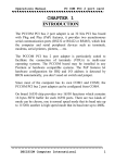
The Plug and Play features let hardware configuration for IRQ and
I/O address is detected by BIOS automatically, so that it need not
switch and jumper setting. However the on board switches can be
used to identify card number by the users (if you do not set the
switch, the PnP BIOS will assign card number automatically).
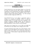
JP1 (Jumper 1)
Select RS422 or RS485 mode for port 1.
JP2 (Jumper 2)
Select receive mode for port 1.
JP3 (Jumper 3)
Select RS422 or RS485 mode for port 2.
JP4 (Jumper 4)
Select receive mode for port 1.
JP5 (Jumper 5)
Select high-speed mode or normal speed mode for port 1.
JP6 (Jumper 6)
Select high-speed mode or normal speed mode for port 1.
SW1 (Switch 1)
Identifies card number.
DECISION Computer International
6
Operations Manual
PCCOM PCI 2 RS422/RS485 Isolator card
DECISION Computer International
7
Operations Manual
PCCOM PCI 2 RS422/RS485 Isolator card
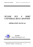
1. Select RS422 or RS485 Mode
JP1
JP3
The JP1 is used to select RS422 or RS485 for port 1 and the JP3 is
used to select RS422 or RS485 for port 2. To short pin 1,2 means
select RS422 mode, otherwise to short pin 2,3 means select RS485
mode.
Jumper
JP1 for port 1
JP3 for port 2
RS422
Short 1,2
Short 1,2
RS485
Short 2,3
Short 2,3
2. Select Receive Mode
JP2
JP4
The JP2 and JP4 are used to select receive mode. To short 1,2
means select receive always enable, and short 2,3 means select RTS
to enable receive. The JP2 is used to select receive mode for port 1
and the JP4 is used to select receive mode for port 2.
Jumper
JP2 for port 1
JP4 for port 2
Receive always enable
Short 1,2
Short 1,2
DECISION Computer International
Enable by RTS
Short 2,3
Short 2,3
8
Operations Manual
PCCOM PCI 2 RS422/RS485 Isolator card
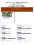
3. Select High Speed or Normal Speed Mode
JP5
JP6
The JP5 and JP6 are used to select high speed mode or normal speed
mode; the clock is 7.3728MHZ for high-speed mode, and
1.8432MHZ for normal speed mode. For high-speed mode, the baud
rate speed up to 460K. The JP5 is used to select speed for port 1 and
the JP6 is used to select speed for port 2.
Jumper
JP5 for port 1
JP6 for port 2
Pin
Short 1,2
Short 2,3
Normal Speed High Speed
Short 1,2
Short 2,3
Short 1,2
Short 2,3
Clock Rate
1.8432MHZ
7.3728MHZ
Mode
Normal Speed
High Speed
4. Card Identifier
The switch is used to identify card number, default setting is card 15.
There are two methods to set the card number:
DECISION Computer International
9
Operations Manual
PCCOM PCI 2 RS422/RS485 Isolator card
a. PnP mode
Just plug in PCCOM PCI bus 2 port adapter into PCI slot, the PCI
BIOS will allocate I/O address to each adapter automatically and
assign card number start from 0 to each adapter. You may set any
card number at PnP mode, and you need use software tools to
distinguish port id. Almost all of the operating systems run at PnP
mode.
b. manual mode
Set card number by card identifier switch, the PCI BIOS will
assign pre-allocated I/O address to each adapter. Please set
different card number to each adapter (do not duplicate card
number setting).
1
2
3
4
OFF
OFF
OFF
OFF
Card Number
15
ON
OFF
OFF
OFF
14
OFF
ON
OFF
OFF
13
ON
ON
OFF
OFF
12
OFF
OFF
ON
OFF
11
ON
OFF
ON
OFF
10
OFF
ON
ON
OFF
9
ON
ON
ON
OFF
8
OFF
OFF
OFF
ON
7
ON
OFF
OFF
ON
6
OFF
ON
OFF
ON
5
ON
ON
OFF
ON
4
DECISION Computer International
10
Operations Manual
PCCOM PCI 2 RS422/RS485 Isolator card
OFF
OFF
ON
ON
3
ON
OFF
ON
ON
2
OFF
ON
ON
ON
1
ON
ON
ON
ON
0
The card number starts from 0 to 15.
DECISION Computer International
11
Operations Manual
PCCOM PCI 2 RS422/RS485 Isolator card
CHAPTER 6
RS422/RS485 CABLING INFORMATION
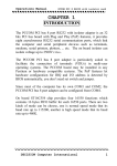
6.1 RS422 Cabling Information for DB9
The communication interface follows the EIA RS422 standard. The
signal assignments for a standard DB9 connector are shown below:
Pin
1
4
5
8
9
Description
Chassis Ground (GND)
Transmit Data+(TxD+)
Transmit Data-(TxD-)
Receive Data+(RxD+)
Receive Data-(RxD-)
To connect the RS422 to other DATA TERMINAL EQUIPMENT
(DTE) devices, the developers recommend using a DTE to DTE
connection as shown below.
HOST
Chassis Ground
Transmit Data(+)
Receive Data(+)
Transmit Data(-)
Receive Data(-)
REMOTE
Chassis Ground
Receive Data(+)
Transmit Data(+)
Receive Data(-)
Transmit Data(-)
DECISION Computer International
12
Operations Manual
PCCOM PCI 2 RS422/RS485 Isolator card
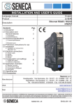
6.2 RS485 Cabling Information for DB9
The RS485 signal assignment is shown as follows.
Pin
1
4
5
8
9
Description
Signal Ground
Transmit Data+(TxD+)
Transmit Data-(TxD-)
Receive Data+(RxD+)
Receive Data-(RxD-)
The RS485 communication is based on cable sharing method, which
is connected as following:
Computer at site 1
TRD+
Computer at site 2
TRD+
TRD–
Ground
TRD–
Ground
Where TRD+ means short pin 4 and pin 8 at connector side, and
TRD- means short pin 5 and pin 9 at connector side. You must short
both pins by yourself.
DECISION Computer International
13
Operations Manual
PCCOM PCI 2 RS422/RS485 Isolator card
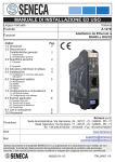
6.3 RS422 Cabling Information for DB25
The communication interface follows the EIA RS422 standard. The
signal assignments for a standard DB25 connector are shown below:
Pin
1
5
7
20
22
Description
Transmit Data-(TxD-)
Receive Data+(RxD+)
Chassis Ground (GND)
Transmit Data+(TxD+)
Receive Data-(RxD-)
DECISION Computer International
14
Operations Manual
PCCOM PCI 2 RS422/RS485 Isolator card
APPENDIX A
PC COM DIAGNOSTIC UNDER MS/DOS
The TESTCOM is a diagnostic program, provide routines to test
your PCCOM PCI 2 port serial adapter under MS-DOS. It has both
internal and external loop back tests. During external loop back test,
a loop back plug must be connected to each port being tested. You
can also select different hardware settings during testing from the
SETUP RS232/RS422 menu.
User can get TESTCOM program from Decision Studio CD.
To test your PCCOM 2 port adapter under MS/DOS, please type
TESTCOM
The TestCom menu will appear.
Setup RS232/RS422 – is used to setup the baud rate etc.
Internal loop test – is used to test the IC.
External loop test – is used to test the ports.
Auto – is used to test the IC and the ports of the card.
DECISION Computer International
15
Operations Manual
PCCOM PCI 2 RS422/RS485 Isolator card
APPENDIX B
PC COM DEVICE DRIVER FOR MS/DOS
B.1 PCCOM Software
The PCCOM software is a high performance, easy to use
RS232/RS422 device driver for PC/486, Pentium or compatibles.
Under MS/DOS environment, you can set up your serial ports by
PCCOM device driver, and these serial ports can be treated as
COM1: and COM2: devices. The setup procedure provides flexible
functions to specify the configuration of multi-serial card, that is,
the hardware configurations of I/O port number, I/O port address,
interrupt and interrupt vector are user selectable.
After the device driver is installed, It takes over communication
between CPU and multi-serial cards such as four port card, eight
port card, ... etc. For each I/O port, the service routine handles a ring
buffer to keep track of all I/O data. Moreover, the PCCOM software
provides library routines (C, PASCAL, BASIC, FoxPro) and DOS
communication interface (DOS device driver, BIOS call) for several
access levels.
For more details, please refer PCCOM manual.
DECISION Computer International
16
Operations Manual
PCCOM PCI 2 RS422/RS485 Isolator card
B.2 Software Installation
When the board is installed, please install software drivers as
follows:
STEP 1: Prepare PCI.OPT file
The PCI.OPT file contents are :
/B:4
/D:COM3
/P:[:2:(2k:9600:N-8-1:RTS+DTR:XON) * 2]
STEP 2: Prepare CONFIG.SYS file
Insert statement into CONFIG.SYS file
For normal speed
DEVICE = PCCOM.SYS @c:\pci.opt
For high speed
DEVICE = PCCOMH.SYS @c:\pci.opt
The syntax of PnP function is
/P:[Card_id:Portno:Port]
The Card_id field is defined as 1 or 2 or 3 or 4 or nil, if you use PnP
mode, just fill nil in card_id field that like step 1, otherwise you can
DECISION Computer International
17
Operations Manual
PCCOM PCI 2 RS422/RS485 Isolator card
specify card_id to match the card identifier switch. The Portno field
is used to specify number of ports in this adapter. The Port field is
defined as PCCOM V2.0.
If
more than one PCCOM board is installed, Please repeat
directive /P of the step 1.
DECISION Computer International
18
Operations Manual
PCCOM PCI 2 RS422/RS485 Isolator card
APPENDIX C
UNIX CONFIGURATION
The distribution CD contains SCO UNIX driver. Our drivers also
provide transparent printer features that let user to connect local
printer from auxiliary port of terminal. The PCI BIOS will assign
card number automatically when you use PnP method, otherwise
you can use card identifier switch to set your card number. The
software installation procedures are shown is the bellows.
C.1 Hardware Configuration
1. First adapter
Port
1
2
Device Name MODEM Name
/dev/ttyj11
/dev/ttyj12
/dev/ttyJ11
/dev/ttyJ12
Transparent
Printer Name
/dev/lpj11
/dev/lpj12
2. Second Adapter
Port
1
2
Device Name MODEM Name
/dev/ttyj21
/dev/ttyj22
/dev/ttyJ21
/dev/ttyJ22
DECISION Computer International
Transparent
Printer Name
/dev/lpj21
/dev/lpj22
19
Operations Manual
PCCOM PCI 2 RS422/RS485 Isolator card
3. Third Adapter
Port
1
2
Device Name MODEM Name
/dev/ttyj31
/dev/ttyj32
/dev/ttyJ31
/dev/ttyJ32
Transparent
Printer Name
/dev/lpj31
/dev/lpj32
4. Fourth Adapter
Port
1
2
Device Name MODEM Name
/dev/ttyj41
/dev/ttyj42
/dev/ttyJ41
/dev/ttyJ42
Transparent
Printer Name
/dev/lpj41
/dev/lpj42
C.2 Software Installation
The installation procedure for the device drivers is described as
follows:
Login as a root user.
Insert distribution CD (which contains device drivers) into
CD-ROM drive d:, then copy the files from the distribution
CD to a temporary directory.
#cd /
# doscp d:dc.tz ./dc.tar.Z
# zcat dc.tar / tar xvfp To install device drivers, please type:
DECISION Computer International
20
Operations Manual
PCCOM PCI 2 RS422/RS485 Isolator card
#cd /usr/sys/pccom/dc
# ./install
Reboot the system. Now, your new UNIX system that
includes device drivers is activated.
Enable each terminal by using the enable command.
# enable ttyj11
# enable ttyj12
.
.
Connect each terminal to connector.
NOTE:
If the new system fails to reboot, please boot the original
system. When system is boot, please press return key to halt
autoboot, then type
:unix.old
To remove device driver from UNIX, please type
a. login as a root user
b. # cd /usr/sys/pccom/dc
c. Remove PCCOM Driver from the kernel
#./ remove
DECISION Computer International
21
Operations Manual
PCCOM PCI 2 RS422/RS485 Isolator card
After installation, please enable each port by enable
command and disable port by disable command.
#disable ttyj11
To change baud rate, please update /etc/inittab and
/etc/conf/cf.d/init.base files.
C.3 Option for High Speed
The configuration of High-Speed Baud Rate card is change as
follows:
Original
50
75
110
134
150
200
300
600
1200
2400
4800
9600
EXTA
EXTB
Extensible
14.4 K
28.8 K
57.6 K
76.8 K
115.2 K
153.6 K
230.4 K
460.8 K
1200 (unchanged)
2400 (unchanged)
4800 (unchanged)
9600 (unchanged)
19200 (unchanged)
38400 (unchanged)
DECISION Computer International
22
Operations Manual
PCCOM PCI 2 RS422/RS485 Isolator card
C.4 Transparent Printer
The default device names to Transparent Printer(TP) are
/dev/lpXYY, that is, the prefix name is changed from "tty" to "lp"
but the other "XYY" is the same. e.g. under default device names,
the corresponding TTY line of /dev/lpj11 is /dev/ttyj11.
By multiplexing a serial line, there are two sorts of data channels for
TTY data(by /dev/ttyXYY) and TP data(by /dev/lpXYY). If the
/dev/ttyj11 is used for a TTY, it has to be enabled before you would
like to print data through /dev/lpj11 to a printer that connected to the
terminal that is operated via /dev/ttyj11.
The channel for TP data that is uni-directional is used to transmit the
data from a host to a terminal only. The differentiates of TTY data
and TP data in the same serial line is that TP data are encapsulated
within a couple of PRINT-ON and PRINT-OFF escape strings that
are recognized by connected terminals. The PRINT-ON and
PRINT-OFF is defined by connected terminals.
The scheme to multiplex a serial line for these two channels is based
on time-division method. The time slices for TTY or TP data are
generated according to the entry procedure, polling, in the PCCOM
driver, which is periodically called by system clock. The period of
system clocks is different among various operating systems, e.g.
most UNIXs is 100hz, but SCO Xenix is 50hz.
The interval reserved for TTY or TP channel in the same serial line
is important to output TP data to a low-speed printer through highthroughput line from PCCOM cards if there is no flow control
XON/XOFF to the serial line.
DECISION Computer International
23
Operations Manual
PCCOM PCI 2 RS422/RS485 Isolator card
The lpx command is used to adjust the time interval for TTY or TP
data and the TP protocol.
lpx [option] device name
option:
-t number: set interval for TTY
-l number: set interval for Transparent Printer
-n string: set esc string to turn on printer
-f string: set esc string to turn off printer
-T : get interval for TTY
-L : get interval for Transparent Printer
-N : get esc_string to turn on printer
-F : get esc_string to turn off printer
device_name : lpXYY
The range of interval reserved for TTY or TP channel is from 1 to
maximum integer. The default setting for any /dev/lpXYY is as
follows:
Interval for TTY : 50
Interval for TP : 1
PRINT - ON escape : “\033[5i” (ESC[5i)
PRINT – OFF escape : “\033[4i” (ECS[4i)
The examples to invoke lpx
Set 60 time slices reserved for /dev/ttyj11
DECISION Computer International
24
Operations Manual
PCCOM PCI 2 RS422/RS485 Isolator card
# lpx -t 60 /dev/ttyj11
Set 2 time slices reserved for /dev/lpj11
# lpx –12 /dev/lpj11
Get the time slices reserved for /dev/lpj11
# lpx –L /dev/lpj11
Set PRINT-ON string for /dev/lpj11
# lpx –n “\033[51” /dev/lpj11
Get PRINT-OFF string for /dev/lpj11
# lpx –F /dev/lpj11 \033[4i
DECISION Computer International
25
Operations Manual
PCCOM PCI 2 RS422/RS485 Isolator card
APPENDIX D
WINDOWS95/98 CONFIGURATION
Welcome to the Decision PCCOM PCI cards series. This series
enables you to utilize the built in plug and play functionality of
Windows 95/98, combined with the power of PCI based serial
communication.
D.1 Installation
1. For optimum PnP functionality, please install one card at a time.
2. Unplug your PC, open it and install one Decision PCCOM PCI
card.
3. Start your computer and wait until Windows 95/98 is loaded.
4. Windows 95/98 will detect the new PCI card that is installed in
your computer, and will prompt you for a proper driver.
5. Insert the device driver CD into your computer, and make sure
Windows 95/98 finds the drivers by eventually browsing
through the directory structure of the CD.
6. After installing the core device drivers for the PCI card,
Windows 95/98 will detect and install software for each COM
port on the card. This may take 5 to 10 seconds per port.
7. After Windows 95/98 has detected and configured all ports, you
may begin using the PCI card. To verify that the installation
process completed successfully, please proceed into the Control
Panel / System / Device Manager.
8. Locate the additional COM ports in the ports section.
If you need install more than one card, please run above
procedure again. Never try to install 2 or more cards at the same
time for you will have errors in installation.
DECISION Computer International
26
Operations Manual
PCCOM PCI 2 RS422/RS485 Isolator card
D.2 Remove Ports
1.
2.
Go to
[Control Panel
Applet]\[System]\[Device
Manager]\[Ports].
Select the port you want to remove then press “Remove” to
delete specified port. Reboot for changes to take effect.
DECISION Computer International
27
Operations Manual
PCCOM PCI 2 RS422/RS485 Isolator card
APPENDIX E
WINDOWS2000 CONFIGURATION
Welcome to the Decision PCCOM PCI cards series. This series
enables you to utilize the built in plug and play functionality of
Windows 2000, combined with the power of PCI based serial
communication. During the boot-up of Windows 2000 the hardware
will be automatically detected by the WINDOWS 2000, just ignore
this dialog box by clicking cancel and during login, use the
administrator user name for installation
E.1 Installation
1. For optimum PnP functionality, please install one card at a time.
2. Unplug your PC, open it and install one Decision PCCOM PCI
card.
3. Start your computer and wait until Windows 2000 is loaded.
4. Windows 2000 will detect the new PCI card that is installed in
your computer, and will prompt you for a proper driver.
5. Insert the device driver CD into your computer, and make sure
Windows 2000 finds the drivers by eventually browsing through
the directory structure of the CD.
6. After installing the core device drivers for the PCI card,
Windows 2000 will detect and install software for each COM
port on the card.
7. After Windows 2000 has detected and configured all ports, you
may begin using the PCI card. Inside the Control Panel, you will
see the Icon of Decision PCCOM Adapters, indicating that the
driver has been successfully installed..
8. Double click the Icon Decision PCCOM Adapters, another
window will appear on screen and will display an installed card
with corresponding COM port.
DECISION Computer International
28
Operations Manual
PCCOM PCI 2 RS422/RS485 Isolator card
If you need install more than one card, please run above
procedure again. Never try to install 2 or more cards at the same
time for you will have errors in installation.
E.2 Remove Ports
1. Go to [Control Panel Applet]\[Decision PCCOM Adapters].
2. Select the port you want to remove then press “Remove Port” to
delete specified port. Reboot for changes to take effect.
DECISION Computer International
29
Operations Manual
PCCOM PCI 2 RS422/RS485 Isolator card
APPENDIX F
WINDOWS/NT CONFIGURATION V3.5 up
Welcome to the Decision PCCOM PCI cards series. This series
enables you to utilize the built in plug and play functionality of
Windows NT, combined with the power of PCI based serial
communication.
F.1 Installation
1. For optimum PnP functionality, please install one card at a time.
2. Unplug your PC, open it and install one Decision PCCOM PCI
card.
3. Start your computer and wait until Windows NT is loaded.
4. Insert the device driver CD into your computer. The CD is auto
run, so you just wait until Decision Studio Applet appears.
5. Click “Device Drive” button, “Windows Operating System”
then a selection of windows operating system platform appears.
6. Click “Windows NT” |button to view the device list of different
hardware products.
7. Select “PCCOM Multi Port Serial Card”. Install Shield will do
installation, for you just click “Next” When windows prompts
you to resume installation procedure.
8. To configure, go to [Control Panel]\[Decision PCCOM
Adapters]. Click the “+” of the card you want configure, then
select which COM port you want to set.
F.2 Remove Ports
Go to [Control Panel]\[Ports] then select what you want to remove
and click “Delete” to remove ports.
DECISION Computer International
30
Operations Manual
PCCOM PCI 2 RS422/RS485 Isolator card
F.3 Uninstall
Enter [Control Panel]\[Decision PCCOM Adapter], and click
[Completely Remove Driver].
DECISION Computer International
31
Operations Manual
PCCOM PCI 2 RS422/RS485 Isolator card
APPENDIX G
LINUX CONFIGURATION
The PCCOM PCI bus 2 port adapter can be installed in the Linux by
using serial device driver supported by Linux. For more details,
please refer to 'setserial' man-pages.
Please uncomment the appropriate lines in /etc/rc.d/rc.serial to
enable auto-configuration of PCCOM PCI bus 2 port card.
For example, uncomment the following lines for PCCOM PCI bus 2
port card.
${SETSERIAL} /dev/cua4 ${AUTO_IRQ}autoconfig${STD_FLAGS}
${SETSERIAL} /dev/cua5 ${AUTO_IRQ}autoconfig${STD_FLAGS}
DECISION Computer International
32
Operations Manual
PCCOM PCI 2 RS422/RS485 Isolator card
APPENDIX H
DIAGNOSTIC UNDER WINDOWS
After installing the PCCOM PCI bus 2 port adapter to your
computer, you can test it if it is functioning correctly via
HyperTerminal (a Windows package communication program), or
by using the Decision Terminal (a software of the Decision
Computer International Co. Ltd.) included on the CD. Just make
sure that there is a loop back plug connected to the COM Port under
test.
H.1 Using Hyper Terminal
To test the card using the Hyper Terminal. Please do the following
steps:
1.
Run the HyperTerminal program.
2.
During connection, the program will ask you to enter your
name and choose an icon for the connection. Enter any
name and select any icon.
3.
After entering your name and selecting icon you will be ask
for country code, area code, phone number and connect
using what. Ignore all edit box except for the connect using,
click the combo box and select Direct to COMx (You can
use any port but usually the COM1 and COM2 is used by
the computer motherboard).
4.
Put the proper COM x properties.
5.
You can now begin to type any message. Take note that
DECISION Computer International
33
Operations Manual
PCCOM PCI 2 RS422/RS485 Isolator card
whatever you type must appear to the textbox as long as
you have a loop back on the COM port of your card!
H.2 Using Decision Terminal
To test the card using the Decision Terminal. Please do the
following steps:
1.
Install the software using the Decision Studio (It is inside
the CD AutoOpen program).
2.
Run the program (Decision Terminal) at the program menu
of the start menu.
3.
Setup the COM port properties by selecting the setup
option on the File menu.
4.
You can now begin to type any message to transmit
textbox. Take note that whatever you type must appear to
receive textbox as long as you have a loop back on the
COM port of your card.
5.
You can also click the Test button to test your card
automatically.
DECISION Computer International
34
Operations Manual
PCCOM PCI 2 RS422/RS485 Isolator card
APPENDIX I
SOFTWARE DEVELOPMENT
INFORMATION
In the Decision Studio CD, it contains PCCOM device driver for
WINDOWS 3.1/95/98/2000/NT/ME/XP, DOS, OS/2, UNIX, Linux,
and the development tools for serial communication and
telecommunication.
I.1 PCCOM Professional
The PCCOM Professional is the Serial Communication Software
Development Tool Kits Under Windows 95/98/2000/NT/ME/XP. It
contains Complete OCX and DLL Microsoft Win32 API software
accessory function for application software developer. It is an easy
to use tool and speed up serial communication application software
development time and cost. Wide compatibility range hardware
support for PCCOM multiport serial card and any standard port, and
support Zmodem and Kermit file transfer protocols for ASCII, Text
and Executable file.
I.2 PCCOM RemoteCom
The PCCOM RemoteCom is an OCX programming development
tool for made application software. That will use to enhance RS232/422 serial communication through Internet or Intranet by standalone program or by browser through World Wide Web (WWW)
under Windows 95/98/2000/NT/ME/XP. User may call OCX
functions to communicate with RemoteCOM both Server and Client
using Internet communication; or encapsulate OCX function and
remote serial ActiveX Control, then run development application
DECISION Computer International
35
Operations Manual
PCCOM PCI 2 RS422/RS485 Isolator card
program under Internet browser (IE and Netscape).
I.3 PCCOM TeleCom
The PCCOM TeleCom is an OCX software accessory suitable for
software engineer to develop application program under Windows
95/98/2000/NT/ME/XP environment. It really makes computer and
communication application combine together. Wide compatibility
range hardware support for PCCOM multiport serial card and any
standard port. The PCCOM TeleCom software kit supports five
major telecommunication functions, which can be used to
1. Send message to “PAGER”(BB Call).
2. Send and receive “VOICE MAIL” from computer to telephone or
portable phone.
3. Send and receive E-MAIL.
4. Send and receive FAX.
5. Receive DTMF.
I.4 PCCOM RemoTeleCom
The PCCOM Remote TeleCom is an OCX programming
development tool for made application software. That will use to
enhance PCCOM TeleCOM functions (Pager, E-mail, Voice mail,
Fax) through Internet or Intranet by stand-alone program or by
browser through World Wide Web (WWW) under Windows
95/98/2000/NT/ME/XP. User may call OCX functions to
communicate with Remote devices both Server and Client using
Internet communication; or encapsulate OCX function and remote
ActiveX Control, then run development application program under
Internet browser (IE and Netscape).
DECISION Computer International
36
Operations Manual
PCCOM PCI 2 RS422/RS485 Isolator card
I.5 PCCOM SCOPE
PCCOM SCOPE is a software that monitors all the data and signals
between two interacting devices, or a single device. With PCCOM
SCOPE you can transform your PC into a total RS-232 analyzer
without the need of expensive hardware or plug in boards. PCCOM
SCOPE creates an unsurpassed tool for RS-232 device driver,
communications protocol and traffic analysis.
I.6 REMOTE CONTROL SOFTWARE
We also provide other hardware with complete Internet/Intranet
remote control software tool for more function availability
Decision Industrial Interface
The Decision Industrial Interface was created to provide a standard
way to access the functionality provided by all data acquisition
products.
Decision Industrial Control
Develop a program controlling the Industrial digital and analog
cards remotely at any part of the world using the Internet
technology! Done it in your application program or via Internet
browser! It extends Decision Industrial Interface from single
computer development environment to client-server development
environment.
Remote Voice
Long distance call will not be expensive as before. There is no
cheaper way to talk to your friend from another country than to talk
through Internet! And the good news is that you can develop your
own software with Remote sound!
DECISION Computer International
37
Operations Manual
PCCOM PCI 2 RS422/RS485 Isolator card
Remote Chat
This development tool is used for chatting / communicating with
another computer in the Internet / Intranet.
Remote White Board
This development tool uses client – server remote drawing board,
every client can shared their image drawn on server drawing board.
Remote Image Capture
This development tool allows you to capture images taken from the
CCD camera via Internet.
Pinger
This development tool make it possible for you to make a program
that check if your still connected to the network or internet and
check the speed of the response of your connection!
Internet Location Server
This development tool is used to find an IP address of a particular
client / computer in the Internet by just specifying its email address!
Remote Access Server
This development tool use to dial-up like and phone dialer
technology, able to dial an ISP and monitor some of some IP
address on network
DECISION Computer International
38
Operations Manual
PCCOM PCI 2 RS422/RS485 Isolator card
APPENDIX J
WARRANTY INFORMATION
J.1 Copyright
Copyright DECISION COMPUTER INTERNATIONAL CO., LTD
All rights reserved. No part of PCCOM software and manual may
be reproduced, transmitted, transcribed, or translated into any
language or computer language, in any form or by any means,
electronic, mechanical, magnetic, optical, chemical, manual, or
otherwise, without the prior written permission of DECISION
COMPUTER INTERNATIONAL CO., LTD.
Each piece of PCCOM package permits user to use PCCOM only
on a single computer, a registered user may use the program on a
different computer, but may not use the program on more than one
computer at the same time.
Corporate licensing agreements allow duplication and distribution
of specific number of copies within the licensed institution.
Duplication of multiple copies is not allowed except through
execution of a licensing agreement. Welcome call for details.
J.2 Warranty Information
DECISION warrants that for a period of one year from the date of
purchase (unless otherwise specified in the warranty card) that the
goods supplied will perform according to the specifications defined
in the user manual. Furthermore that the PCCOM product will be
supplied free from defects in materials and workmanship and be
fully functional under normal usage.
DECISION Computer International
39
Operations Manual
PCCOM PCI 2 RS422/RS485 Isolator card
In the event of the failure of a PCCOM product within the specified
warranty period, DECISION will, at its option, replace or repair the
item at no additional charge. This limited warranty does not cover
damage resulting from incorrect use, electrical interference,
accident, or modification of the product.
All goods returned for warranty repair must have the serial number
intact. Goods without serial numbers attached will not be covered
by the warranty.
Transportation costs for goods returned must be paid by the
purchaser. Repaired goods will be dispatched at the expense of
PCCOM.
To ensure that your PCCOM product is covered by the warranty
provisions, it is necessary that you return the Warranty card.
Under this Limited Warranty, DECISION's obligations will be
limited to repair or replacement only, of goods found to be
defective as specified above during the warranty period. DECISION
is not liable to the purchaser for any damages or losses of any kind,
through the use of, or inability to use, the PCCOM product.
DECISION reserves the right to determine what constitutes
warranty repair or replacement.
Return Authorization: It is necessary that any returned goods are
clearly marked with an RA number that has been issued by
DECISION. Goods returned without this authorization will not be
attended to.
DECISION Computer International
40