1
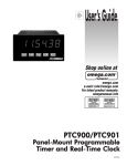
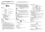
Heinkelstrasse 5
D-71272 Renningen
Phone (49) 0 7159 923-0
Fax (49) 0 7159 923 108
User Manual
Climate Controller KR494
Version without Roof-top Heating
Issue: Februar 2003
Software V1.05
Page : 1 / 7
Heinkelstrasse 5
D-71272 Renningen
Phone (49) 0 7159 923-0
Fax (49) 0 7159 923 108
1 Key Functions
T1
T2
T22
T21
T11
T3
T12
T4
T23
T24
T25
T6
T28
T27
T26
T13
T5
T14
T15
T29
T16
1.1 Standard functions
The function is active, if the corresponding key-LED is on.
Abbrevations: ZA = Ignition/Battery off, ZE = Ignition/Battery on, ME = Engine on
Function
Description
Requirement
T1: recirculated air
front box
Change-over recirculated air/fresh air operation frontbox.
ZE, defrost function
inactive (key function
T3)
T2: temperature
control front box
On/off-switching of temperature control frontbox. According to ZE, defrost function
set-/actual-value of the temperature the water valve und the inactive (key function
refrigerant valve of the frontbox are controlled. (refrigerant valve only T3)
with running air-conditioning of the passenger compartment)
T3: defrost function
front box
On/off-switching of defrost function front box. The water valve opens ME
completely, the blower runs with full power. The recirculated air flap
changes to position of fresh air. By activating this function all other
actual functions are stored and with deactivating restored again. (Keys
T1, T2, T12, T22, T13, T23 are not in function during defrost
operation)
T11: distribution of
upper air
no function with this version
T21: distribution of
lower air
no function with this version
T12/T22: Temperature By pressing T12 the set value of the frontbox temperature control ZE, defrost function
setting front box
increases in steps of 1K, by pressing T22 the set value decreases in inactive (key T3),
temperature control
steps of 1K. (range from 18°C to 28°C)
front box active (key
T2)
Page : 2 / 7
Heinkelstrasse 5
D-71272 Renningen
Phone (49) 0 7159 923-0
Fax (49) 0 7159 923 108
Function
Description
Requirement
T13/T23: blower
setting front box
The blower speed of the front box increases (1 step) by pressing T13, ZE, defrost function
resp. decreases by pressing T23. The max. step is 6 with function ME, inactive (key T3)
otherwise 3. If Step 0 (blower off) is set, key-LED T13 turns off. During
air-conditionining operation of the frontbox it is not possible to switch
off the blower
T24: Clock setting
modes
no function with this version
T25: Passenger
compartment
temperature display
Display temperature passenger compartment
ZE
T26: outside
temperature display
Display outside temperature
ZE
T4: temperature
control of passenger
compartment
On/off switching of temperature control of passenger compartment. ZE
Convector valve, air-conditioning, air flaps and the blower speed are
controlled in dependence of the set-/actual-value of the temperature
T5: Manual ventilation
of passenger
compartment
On/off switching of manual ventilation of passenger compartment.
T6: recirculated air
of passenger
compartment
The passenger compartment is set in return air operation. If this ZE
function is deactivated and temperature control is active, the flap
position is set in dependance of of the temperature. If this function is
deactivated and temperature control is not active, the flap is set in
fresh air position.
ZE
T14/T27: Temperature By pressing T14 the set value of the frontbox temperature control key function
increases in steps of 1K, by pressing T27 the set value decreases in temperature control
setting of passenger
passenger
steps of 1K. (range from 18°C to 28°C)
compartment
compartment (T4)
active
T15/T28:
The blower speed of the front box increases (1 step) by pressing T15, key function manual
resp. decreases by pressing T28. The setting range with ME is step 1 ventilation passenger
compartment (T5)
– 6, with ZE step 1 - 3
active
T16: Reheat operation no function with this version
T29: Auxiliary heating
no function with this version
Page : 3 / 7
Heinkelstrasse 5
D-71272 Renningen
Phone (49) 0 7159 923-0
Fax (49) 0 7159 923 108
1.2 Special functions
Function
Description
Requirement
T14: Forced heating
of passenger
compartment
If the setpoint is set to 28°C, the passenger compartment is forced to ME
heat by a renewed permanent pressing of this key about 2 seconds.
The setpoint is indicated as an „:H:“, the convector valve completely
opens.
T27: Forced cooling
of passenger
compartment
If the setpoint is set to 18°C, the passenger compartment is forced to ME
cool by a renewed permanent pressing of this key about 2 seconds.
The setpoint is indicated as a „:C:“, the convector valve completely
closes, air conditioning is switched on, the roof blowers are forced to
run with maximum speed.
T25 + T26
simultaneously:
LCD-display contrast
By simultaneously pressing of these keys the LCD-display contrast ZE
increases to 1 step. After reaching the maximal contrast the display
contrast is set to minimum.
T1 + T6
simultaneously:
Test program
Simultaneously pressing of these keys: Start of test programs to check all electronical components and connected units.
Simultaneously pressing of these keys forces a „Reset“.
T1 + T11 + T21
simultaneously:
(equivalence to conect/ disconect the power supply)
Renewed start (Reset)
-
2 Display functions
Function
Description
Requirement
Displayed set point
of the frontbox
Set point in °C
Displayed set point
of passenger
compartment
Set point in °C, resp. „:H:“ forced heating , „:C:“ forced cooling
Displayed blower
speed of passenger
compartment
Blower speed of passenger compartment step 1 ... 6
Displayed inside
temperature
Inside temperature in °C
Displayed outdoor
temperature
Outdoor temperature in °C, automaticallay displayed, if outdoor
temperature is below 3°C.
Displayed state
of air-conditioning
The air-conditioning symbol is displayed, if air-conditioning is on.
„P<“ symbol is indicated, if under pressure is detected and
„P>“ symbol is indicated, if over pressure is detected while airconditioning is in operation.
Displayed state
of frost warning
The frost warning symbol is displayed, if outdoor temperature is less
than 3°C. After 10 seconds outdoor temperature is automatically
displayed.
Displayed state
of battery voltage
If the battery voltage is less than 21,5V for more than 30 seconds, it is
indicated on the display. In this state all functions of the system are
locked. If the battery voltage is higher than 25V for more than 30
seconds all functions are released again.
Page : 4 / 7
Heinkelstrasse 5
D-71272 Renningen
Phone (49) 0 7159 923-0
Fax (49) 0 7159 923 108
3 Test programs
Switching and state-displaying of all connected units are enabled any time by the test programs. If running
these, there is no monitoring of the outputs. For that reason only qualified technicians may execute this!
Key
Display
Description
Start: T1 + T6
simultaneous
Stop: T1
Test menue: The version of software is displayed (for example 105).
The different test programs are selected by all „+“/“-“ keys. (T12, T22, T13, T23,
T14, T27, T15, T28). The selected test program ist displayed inverted.
(In this example: Test „LED“)
T26: Start
T6: Stop
LED- test: All key-LEDs are switched on in succsession: T1, T2, T3, T4, T5, T6,
T11, T13, T16, T21, T24, T25, T26, T29
T26: Start
T6: Stop
LCD- test: The LCD display is filled from the left to the right side and erased
subsequently.
T26: Start
T21 + T29
simultaneous:
Stop
Key- test: The keys are displayed by rectangles: a pressed key by a filled, an
unpressed key by unfilled rectangle.(In this example: T26 is pressed).
Attention: It is not possible to display more than one pressed key!
T26: Start
T6: Stop
Servo-motor- test: With keys „+“/“-“ the different servo-motors are selected. The
two outputs and the potentiometer input of the selected servo-motor are displayed.
If there is no connection to the CAN-bus-node with the selected servo-motor, a
flashing symbol „=/=“ is displayed.
With keys T11 and T21 the direction of the motor is controlled. The display
changes from „OFF“ to „ON“. There is a correct working of the servo, if you press
key T11 and the display symbol changes from „OUT +“ to „ON“ just as the value of
the potentiometer input decreases.
T26: Start
T6: Stop
Output- test: With keys „+“/“-“ the different outputs are selected. The selected
output is displayed inverted. The state of the output is displayed by „ON“ or „OFF“.
If there is no connection to the CAN-bus-node with the selected output, a flashing
symbol „=/=“ is displayed. With keys T11 and T21 the actually selected output is
switched, without dependace of temperature control .
T26: Start
T6: Stop
Input-test: With keys „+“/“-“ the different inputs are selected. The state of the input
is displayed by „ON“ or „OFF“. If there is no connection to the CAN-bus-node with
the selected input, a flashing symbol „=/=“ is displayed.
T26: Start
T6: Stop
Can-Bus test: The version of software of the connected node is displayed. Nodes
without connection are displayed by a flashing „=/=“.
T26: Start
T6: Stop
Blower test: The state of blowers or groups of blowers is displayed. With keys
„+“/“-“ the different blower(-groups) are selected. The actually selected group is
diplayed inverted.
With keys T11 and T21 the actually selected output is switched (slow/fast), without
dependace of temperature control .
Page : 5 / 7
Heinkelstrasse 5
D-71272 Renningen
Phone (49) 0 7159 923-0
Fax (49) 0 7159 923 108
4 Control and adjust functions
4.1 Initial switching on
After connecting the power supply and initial switching of ignition/battery the functions of frontbox- ,
passenger compartment- temperature control and frontbox blower are activated.
4.2 Functions ZA
With ignition off the display is deactivated too. There are only available the functions of test program and
Reset.
4.3 Functions ZE
With ignition/battery on all functions are available, except frontbox and defrost. Temperature control of the
passenger compartment only runs in convector heating mode. Roof blowers and air-conditioning are
deactivated. A manual activating of the roof blowers is possible. The speed control of roof blowers and
frontbox blower is limited by step 3.
With switching off battery/ ignition all active control-/adjust functions are stored. They are restored by a
renewed battery/ ignition switching on.
4.4 Functions ME
With running engine all functions are available.
With switching off the engine the operation modes „forced heating“ and „forced cooling“ are reset to minimal
resp. maximal setpoint. The operation modes of defrost function frontbox are stored wih switching off. They
are restored by a renewed engine switching on.
The test programs are finished because of safety reasons. A renewed start of the test program is possible.
4.5 Under voltage
If the battery voltage is less than 21,5V for more than 30 seconds, it is displayed by a warning „< 21,5V“.
In this state all functions of the system are locked. If the battery voltage is higher than 25V (recharging of
battery) for more than 30 seconds all functions are released again.
4.6 Calibration
The servo motors control works with a position-management. For that, the end points for the servos have to
be measured to find the maximum movement. In order to measure this, both end positions of the valve have
to be reached, and the corresponding parameters of the potentiometers must be internally saved. This
procedure is called Calibrating. For a correct function of the calibrating and the following positionmanagement it is necessary that the potentiometers of the servos motors are connected correctly, and the
servos are moving in a proper way, without any brakes. Via the test mode “Servo” all motors can be
checked. With selecting the output “OUT+“ the displayed potentiometer parameter must decrease, with
“OUT-“ must increase.
Because its possible to interrupt calibrating when starting the test program “servo” the calibrating will be
started from the beginning, after the test program is finalized.
Page : 6 / 7
Heinkelstrasse 5
D-71272 Renningen
Phone (49) 0 7159 923-0
Fax (49) 0 7159 923 108
4.7 Control functions
Abbreviations: TA = temp. outdoor, TS = temp. setpoint, TR = temp. inside , TFB = temp. frontbox
Control states of passenger compartment:
State
Water valves
Roof blowers
Heating with ZE
Convector valve control with P-controller
Change-over to ventilation
not available with ZE
recirculated-/Fres
h-air flaps
off
recirculated air mode
constant 25%
recirculated air mode
Heating with ME
Convector valve control with P-controller
Change-over heating to
ventilation
TA > TS-7,5K, simultaneousTR > TS or if TA > TS-11K, simultaneous TR > TS+3K
Ventilation
closed
Change-over ventilation after
heating
TR < TS – 0,3K
Change-over ventilation after
air-conditioning
TA > TS-10K, simultaneous TR > TS + 0,7K or if TA > TS -14K, simul TR > TS + 5K
Air-conditioning
closed
Air-conditioning off
TA < TS-16K or TR < TS
Control off
closed
constant 25%
Fresh air mode
25%...100% linear increasing Fresh air mode
and
between
TR=TS
TR=TS+4,5K
off
Fresh air mode
Control states of frontbox:
State
Water valve
Heating
PID-Controller
Change-over to cooling
TFB > TS + 1K
Cooling
closed
Refrigerant agent valve off
TFB <= TS
Delay time after
agent valve off
Refrigerant agent valve
off
on, if air-conditioning on
refrigerant TFB > TAnsaug – 1,5K (In depedance of the air flap position outdor- or inside temperature is used) or 5
minutes after refrigerant agent valve switch off.
The registration of frontbox temperature results from a sensor in the air outlet. The adjusted setpoint is
copied to the real setpoint by characteristic curve. The results are the necessary temperatures for screen
clearing.
Schedule of adjusted and depending real set points of the frontbox
Adjusted:
18
19
20
21
22
23
24
25
26
27
28
Real:
16
17,6
19,3
21
26
31
36
41
46
51
56
4.8 Other control functions:
4.8.1 Control of „open door“ – signal
The rotation speed of the roof blowers is reduced to approx. 20% while doors are open.
5 Test program
With starting a test program the actual states of outputs are stored. Modifications by test programms
(„outputs“, „servo“ und „Blower“ )are restored after finishing the test program by running control processes.
Page : 7 / 7