1
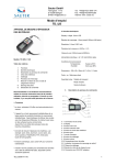
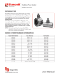
Ultrasonic Thickness Gauge
WT-2 Pipe Wall Thickness Gauge
FEATURES
• Uses the exclusive Micro-computer LSI circuit and crystal
time base for highly accuracy measurements
• A high power of emission and a broad band of receiving
sensitivities make it easy to measure the rough surfaces
such as cast iron
• Widely used in a large variety of industries
• Capable of measuring the thickness of many materials
including steel, cast iron, aluminum, red copper, brass,
zinc, quartz glass, polyethylene, PVC, gray cast iron and
nodular cast iron
• Automatic power off to conserve battery life
Calibration
Stage
mm
Coupling
Established
Icon
• Can communicate with PC computer for downloading
statistics and printing using an optional cable and
software package
inch
Display
• Large selection of pre-programmed materials and sound
velocity values for convenient use
• Automatic and manual shutdown functions
• Coupling quality icon
• Bluetooth data output choice
Transducer
Connections
Power
Switch
Calibration
Key
Units
Selection
Up
Arrow
Down
Arrow
Power
Switch
Velocity
Key
Material
Selection
Ultrasonic
Transducer
COMPONENTS
Standard
RS232
Connection
• Handheld Display
• Transducer
• Acoustic Couplant
• Carrying Case
• Manual
Optional (Sold Separately)
• 5MФ 12 mm high temperature transducer
• 6MФ 6 mm thin material transducer
Figure 1: Gauge description and controls
SPECIFICATIONS
Display
Four digits, 0.4 in. (10 mm) LCD
Resolution
0.004 in. (0.1 mm)
Range
0.0475…7.875 in. (1.2…200 mm) (45#
steel)
Accuracy
±(0.5% n+0.1)
Sound Velocity Range
3281…29,528 fps (1000…9000 mps)
Environmental
• USB data output port
Temperature
32…122° F (0…50° C)
• RS-232 data output port
Humidity
<80%
• Bluetooth data output
TTM-UM-00434-EN-02 (April 2015)
Display Units
Inches and millimeters
Power Supply
Four 1.5V AAA (UM-4 Battery)
Size
5.52 x 2.25 x 1.18 in.
(140 x 70 x 30 mm)
Weight
9.2 oz (260 g) not including batteries
User Manual
Material Selection
MATERIAL SELECTION
1. Press either Power switch to turn on the unit.
2. Press SELECT. The display shows the code cdxx or xxxx. The cd is an abbreviation for code and xx is a number between
01…11 corresponding to a particular pipe material. xxxx is a four-digit user-defined material sound velocity.
3. Press
or
to select the correct pipe material code then. Press SELECT to confirm. The display shows 0. If you select a
material code but do not confirm the selection, the code automatically changes to 0 after several seconds. The meter saves
the material code before exiting.
NNOTE: If you press
while displaying cd11 or cd01, the last user-defined sound velocity displays.
NNOTE: You do not have to select the material code once the code is stored to memory unless you need a new
material choice.
4. To browse the material code choices, press SELECT and then use
or
to scroll through the list. To stop browsing and
make a material selection, press SELECT again. The code changes back to 0 and returns you to the measurement mode.
Code
Material
Code
Material
Code
Material
cd01
Steel
cd05
Brass
cd09
PVC
cd02
Cast Iron
cd06
Zinc
cd10
Gray Cast Iron
cd03
Aluminum
cd07
Quartz Glass
cd11
Nodular Cast Iron
cd04
Red Copper
cd08
Polyethylene
xxxx
Manual Sound Velocity
Table 1: Material codes
CALIBRATION
1. Place a small amount of couplant on the calibration stage.
2. Press CAL. The CAL indicator appears on the display.
3. Press the face of the transducer to the calibration stage. The coupling icon appears if the connection between the
transducer and the calibration stage is established. 0.197 inch or 5.0 mm and CAL alternate on the display. When the
alternation stops, press CAL to confirm. The unit automatically returns to measurement mode.
NNOTE: The unit saves the calibration result automatically once confirmed. It is unnecessary to calibrate often unless the
accuracy of measurement is suspect.
MEASURING PROCEDURE
1. Press either Power switch to turn on the unit.
2. Press Inch
mm to select the desired measurement unit.
3. Select the correct pipe material code. See Table 1.
4. Place a bead of couplant on the pipe surface.
5. Press the transducer onto the pipe surface to make a measurement. The display shows the wall thickness value.
6. Verify that coupling is established and the coupling icon is on (see Figure 1).
NNOTE: The reading is held until a new measurement is made or until the power automatically turns off.
NNOTE: To turn off the power, press either of the power switches or wait until the power automatically turns off after a period
of inactivity.
Page 2
TTM-UM-00434-EN-02
April 2015
Measuring Using a Known Velocity
MEASURING USING A KNOWN VELOCITY
1. Press VEL. The display shows the last pipe sound speed velocity used.
2. Set the known pipe velocity by pressing
or
in velocity mode.
NNOTE: Every press increments or decrements the velocity by 32.8 fps (10 mps). To change the velocity in 328 fps (100 mps)
jumps, press and hold
or
for more than four seconds.
3. Place a bead of couplant on the pipe surface.
4. Press the transducer onto the pipe surface to make a measurement.
5. Verify that coupling is established and the coupling icon is on (see Figure 1). As long as the pipe's sound speed is set
correctly, the reading on display is the wall thickness of the pipe.
MEASURING AN UNKNOWN WALL THICKNESS USING A SAMPLE OF
KNOWN THICKNESS
1. Using a sample pipe of known thickness, obtain the pipe's sound speed value by incrementing or decrementing the sound
speed value until the wall thickness reading matches the known thickness value.
2. When the thickness values match, the velocity reading is the actual sound speed for the pipe sample.
3. With the known velocity for that pipe type set, measurement of the wall thickness of any pipe of the same type can
be done.
BATTERY REPLACEMENT
1. When the battery symbol appears on the display, it is time to replace the batteries.
2. Slide the battery cover away from the instrument and remove the used batteries.
3. Install fresh AAA batteries, paying careful attention to polarity.
April 2015
Page 3
TTM-UM-00434-EN-02
Ultrasonic Thickness Gauge, WT-2 Pipe Wall Thickness Gauge
Control. Manage. Optimize.
Dynasonics is a registered trademark of Badger Meter, Inc. Other trademarks appearing in this document are the property of their respective entities. Due to continuous research,
product improvements and enhancements, Badger Meter reserves the right to change product or system specifications without notice, except to the extent an outstanding
contractual obligation exists. © 2015 Badger Meter, Inc. All rights reserved.
www.badgermeter.com
The Americas | Badger Meter | 4545 West Brown Deer Rd | PO Box 245036 | Milwaukee, WI 53224-9536 | 800-876-3837 | 414-355-0400
México | Badger Meter de las Americas, S.A. de C.V. | Pedro Luis Ogazón N°32 | Esq. Angelina N°24 | Colonia Guadalupe Inn | CP 01050 | México, DF | México | +52-55-5662-0882
Europe, Middle East and Africa | Badger Meter Europa GmbH | Nurtinger Str 76 | 72639 Neuffen | Germany | +49-7025-9208-0
Europe, Middle East Branch Office | Badger Meter Europe | PO Box 341442 | Dubai Silicon Oasis, Head Quarter Building, Wing C, Office #C209 | Dubai / UAE | +971-4-371 2503
Czech Republic | Badger Meter Czech Republic s.r.o. | Maříkova 2082/26 | 621 00 Brno, Czech Republic | +420-5-41420411
Slovakia | Badger Meter Slovakia s.r.o. | Racianska 109/B | 831 02 Bratislava, Slovakia | +421-2-44 63 83 01
Asia Pacific | Badger Meter | 80 Marine Parade Rd | 21-06 Parkway Parade | Singapore 449269 | +65-63464836
China | Badger Meter | 7-1202 | 99 Hangzhong Road | Minhang District | Shanghai | China 201101 | +86-21-5763 5412
Legacy Document Number: 06-SEN-UM-00465-EN