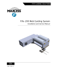
1
D-MAX WEB GUIDE CONTROLLER WITH OPERATOR INTERFACE PANEL USER MANUAL D-MAX OPERATOR INTERFACE (Home Screen is shown) D-MAX CONTROLLER 05/04/2009 © 2007 Fife Corporation. All rights reserved. Figure Sheet 1-886-E This page is intentionally blank. 05/04/2009 © 2007 Fife Corporation. All rights reserved. Figure Sheet 1-886-E D-MAX WEB GUIDE CONTROLLER WITH OPERATOR INTERFACE PANEL USER MANUAL COPYRIGHT COPYRIGHT All of the information herein is the exclusive proprietary property of Fife Corporation, and is disclosed with the understanding that it will be retained in confidence and will be used only for the purpose intended. Any reproduction of this User Manual, in any form, in whole or in part, requires the prior written consent of Fife Corporation. The information given in this User Manual is subject to change without notice. Periodically there will be updates to this manual. The latest version is available at www.fife.com or by calling Fife Corporation. This User Manual has been compiled with the greatest possible care and attention; however, the possibility of error cannot be completely excluded. Fife Corporation accepts no legal liability for incorrect information given and the consequences arising there from. Copyright 2009 Fife Corporation. All rights reserved. 05/04/2009 Page i of vi Figure Sheet 1-886-E This page is intentionally blank. 05/04/2009 Page ii of vi Figure Sheet 1-886-E D-MAX WEB GUIDE CONTROLLER WITH OPERATOR INTERFACE PANEL USER MANUAL TABLE OF CONTENTS COPYRIGHT.................................................................................................................................................. i TABLE OF CONTENTS .............................................................................................................................. iii GENERAL INTRODUCTION ........................................................................................................................ 1 DEFINITION OF TERMS ................................................................................................................. 1 D-MAX GENERAL INFORMATION ................................................................................................. 2 CAUTIONS AND WARNINGS ......................................................................................................... 2 OPERATOR INTERFACE ............................................................................................................................ 3 DISPLAY DEFINITIONS .................................................................................................................. 3 STATUS NUMBER DEFINITION..................................................................................................... 4 KEY DEFINITIONS .......................................................................................................................... 5 OPERATION NOTES....................................................................................................................... 7 GETTING STARTED .................................................................................................................................... 9 CONNECTIONS, OPERATOR INTERFACE, BASIC...................................................................... 9 CONNECTIONS, OPERATOR INTERFACE, NETWORK .............................................................. 9 CONNECTIONS, CONTROLLER.................................................................................................... 9 POWER CONNECTION ................................................................................................................ 10 NETWORK COMMUNICATION .................................................................................................... 10 BASIC SYSTEM SETUP................................................................................................................ 11 MENUS ....................................................................................................................................................... 13 REMOTE CONTROL ..................................................................................................................... 13 Remote Control Menu Structure ....................................................................................... 13 JOB SETTINGS ............................................................................................................................. 13 Guidepoint Offset .............................................................................................................. 13 Auto Setup ........................................................................................................................ 13 Gain................................................................................................................................... 13 OSC .................................................................................................................................. 13 PIC .................................................................................................................................... 14 ASC ................................................................................................................................... 14 Deadband.......................................................................................................................... 14 Polarity .............................................................................................................................. 14 SGC .................................................................................................................................. 14 Max Actuator Speed.......................................................................................................... 14 Job Settings Menu Structure............................................................................................. 15 SC SETTINGS ............................................................................................................................... 16 SC Offset........................................................................................................................... 16 SC Gain............................................................................................................................. 16 SC Polarity ........................................................................................................................ 16 SC Settings Menu Structure ............................................................................................. 16 HARDWARE IOs............................................................................................................................ 17 Sensor Setup .................................................................................................................... 17 Actuator (X4 or X10) ......................................................................................................... 17 Digital Inputs (X1).............................................................................................................. 17 Digital Outputs (X1)........................................................................................................... 17 Hardware IOs Menu Structure .......................................................................................... 18 CONTROL OPTIONS .................................................................................................................... 21 Mode Enable ..................................................................................................................... 21 Job Enable ........................................................................................................................ 21 Jog Keys ........................................................................................................................... 21 Remote Control ................................................................................................................. 21 Length Unit........................................................................................................................ 21 05/04/2009 Page iii of vi Figure Sheet 1-886-E D-MAX WEB GUIDE CONTROLLER WITH OPERATOR INTERFACE PANEL USER MANUAL Hardlock ............................................................................................................................ 21 Control Options Menu Structure ....................................................................................... 22 CONFIGURATION ......................................................................................................................... 24 Names............................................................................................................................... 24 Serial Number ................................................................................................................... 24 FW Number....................................................................................................................... 24 SW Number....................................................................................................................... 24 Distributed System ............................................................................................................ 24 Backup .............................................................................................................................. 24 Restore.............................................................................................................................. 24 Configuration Menu Structure ........................................................................................... 25 NETWORK..................................................................................................................................... 26 TCP/IP............................................................................................................................... 26 MAXNET ........................................................................................................................... 26 FieldBus ............................................................................................................................ 26 MAC-ID ............................................................................................................................. 26 Network Menu Structure ................................................................................................... 26 SERVICE ....................................................................................................................................... 27 MEASURING POINTS ...................................................................................................... 27 SET DIGITAL OUTPUTS.................................................................................................. 27 ERRORS/WARNINGS...................................................................................................... 27 Service Menu Structure .................................................................................................... 27 OPERATOR INTERFACE LOCAL MENUS................................................................................... 29 Language .......................................................................................................................... 29 BMP orientation................................................................................................................. 29 Application Filter................................................................................................................ 29 Connect on start................................................................................................................ 29 Log In ................................................................................................................................ 29 Administration ................................................................................................................... 29 Contrast............................................................................................................................. 29 Background Color ............................................................................................................. 29 Configuration..................................................................................................................... 29 Network (X2…X6) ............................................................................................................. 29 Service .............................................................................................................................. 29 Operator Interface Local Menu Structure ......................................................................... 30 OPERATOR INTERFACE GATEWAY MENUS ............................................................................ 32 Gateway Settings .............................................................................................................. 32 Configuration..................................................................................................................... 32 Network (X2…X6) ............................................................................................................. 32 Gateway Menu Structure .................................................................................................. 33 SPECIFIC PROCEDURES ......................................................................................................................... 35 APPLICATION FILTERING ........................................................................................................... 35 Overview ........................................................................................................................... 35 Configuring the System for Application Filtering............................................................... 35 Assigning Names For “All Applications” Filtering.............................................................. 37 Assigning Names For “Selected Applications” Filtering.................................................... 37 Filtered / All (F5) Key ........................................................................................................ 37 Disable Application Filtering.............................................................................................. 37 Application Filtering, Example #1...................................................................................... 38 Application Filtering, Example #2...................................................................................... 39 Application Filtering, Example #3...................................................................................... 40 PASSWORD PROTECTION ......................................................................................................... 41 Overview ........................................................................................................................... 41 Initial Entry of Passwords.................................................................................................. 42 05/04/2009 Page iv of vi Figure Sheet 1-886-E D-MAX WEB GUIDE CONTROLLER WITH OPERATOR INTERFACE PANEL USER MANUAL Changing Password Levels .............................................................................................. 42 Entering Password Protected Menus................................................................................ 42 Disable Password Protection ............................................................................................ 43 Reset Passwords .............................................................................................................. 43 Password Administration Menu Structure......................................................................... 43 SENSOR CALIBRATION, EDGE SENSORS ................................................................................ 45 Overview ........................................................................................................................... 45 Calibration, Guiding To The Edge Of A Web.................................................................... 45 Sensor Input Port Selection Chart .................................................................................... 46 Sensor Calibration Menu Structure................................................................................... 46 SENSOR CALIBRATION, LINE SENSORS .................................................................................. 47 Overview ........................................................................................................................... 47 Calibration, Guiding To The Center Of A Continuous Line............................................... 47 Calibration, Guiding To The Edge Of A Continuous Line ................................................. 48 Calibration, Guiding To The Center Of A Broken Line...................................................... 48 ENCODER CALIBRATION ............................................................................................................ 50 Overview ........................................................................................................................... 50 Calibration, Position Feedback Encoder........................................................................... 50 Encoder Calibration Menu Structure................................................................................. 51 LINE SPEED INPUT CALIBRATION ............................................................................................. 52 Overview ........................................................................................................................... 52 Calibration, Line Speed Input............................................................................................ 52 Line Speed Input Calibration Menu Structure................................................................... 52 DIGITAL INPUT/OUTPUT MATRIX ........................................................................................................... 53 DIGITAL INPUT MATRIX............................................................................................................... 53 DIGITAL OUTPUT MATRIX........................................................................................................... 53 SYSTEM NOTES ........................................................................................................................................ 55 TROUBLESHOOTING................................................................................................................................ 57 FAULT DIAGNOSTICS – FAULT RECTIFICATION...................................................................... 57 LED INDICATIONS ........................................................................................................................ 58 EN LED ............................................................................................................................. 58 PWR LED.......................................................................................................................... 58 FN LED ............................................................................................................................. 58 Power LED ........................................................................................................................ 58 Network LED ..................................................................................................................... 59 Ethernet connector LED's on the OI-B.............................................................................. 59 Ethernet connector LED's on the OI-N ............................................................................. 59 STATUS ICONS............................................................................................................................. 60 FUSE REPLACEMENT.................................................................................................................. 61 RETURN SHIPMENT INSTRUCTIONS ........................................................................................ 62 MOTOR/VALVE LIST..................................................................................................................... 63 SPECIFICATIONS ...................................................................................................................................... 65 GENERAL ...................................................................................................................................... 65 CERTIFICATIONS AND ENVIRONMENTAL COMPATIBILITY.................................................... 66 VIBRATION AND SHOCK ............................................................................................................. 66 INPUTS AND OUTPUTS ............................................................................................................... 67 MAXIMUM CABLE LENGTHS....................................................................................................... 68 INDEX ......................................................................................................................................................... 69 05/04/2009 Page v of vi Figure Sheet 1-886-E D-MAX WEB GUIDE CONTROLLER WITH OPERATOR INTERFACE PANEL USER MANUAL This page is intentionally blank. 05/04/2009 Page vi of vi Figure Sheet 1-886-E D-MAX WEB GUIDE CONTROLLER WITH OPERATOR INTERFACE PANEL USER MANUAL GENERAL INTRODUCTION DEFINITION OF TERMS 1. Actuator – The device that provides movement in the system (motor, hydraulic cylinder, etc.). 2. ASC – (Automatic Sensor Control) A window comparator, which triggers when the strip/web moves out of the window range of the sensor bandwidth. Guiding is suspended when ASC is active. The comparator window is adjustable. ASC is active in Automatic mode, only. 3. Automatic Mode – In this mode, guiding is provided in response to sensor signal input. 4. Auto Setup – Automatic adjustment of System Gain, Polarity, and Guidepoint. 5. Controller – The electronics processing unit that controls and drives the actuators that are attached to it, in response to position feedback from the sensors. 6. Deadband – A defined window symmetrical about the center of the sensor bandwidth in which no guiding occurs. 7. Device – The name of the Controller, which is currently selected by the Operator Interface. 8. Drive – The name of the drive within the Controller, which is currently selected by the Operator Interface. 9. External Lock – This is a command that temporarily disables the guiding loop while in Automatic Mode. The command must be maintained for this feature to be active. Once the command is removed, the system returns to active guiding. No motor drive or servo-valve drive is allowed while the External Lock command is present. 10. E-Stop – This is a condition in which the electro-mechanical drive is disabled by removing power from the actuator drive circuitry. This is obtained by removing the DC Power from the drive input and then grounding this input. This prevents any power getting to the electro-mechanical actuator. This feature is not available for hydraulic drive systems. 11. Gain – The System Gain, which controls the tightness of the control loop for guiding or centering of the guide structure. 12. Guidepoint / Guidepoint Offset – An offset to the default Guidepoint which is then used for guiding. 13. Home Screen – As indicated on the front page of this User Manual, this is the top-level screen that is normally used by the operator of the D-MAX Web Guide Controller. The Home Screen Status Number is “XX” (depending on Mode and Job Selection). 14. MAC Address – (Media Access Control). This is the factory assigned hardware address of a D-MAX device. MAC Address is also referred to as MAC-ID. 15. Manual Mode – In this mode, no guiding is provided. Left and right arrow keys are used for jogging the actuator (if enabled). All menu selections may be accessed in this mode. 16. MAXNET – This is the Fife proprietary serial protocol that is used for communications between DMAX devices. This is a deterministic protocol. Therefore, the MAXNET network must be isolated from other Ethernet networks that do not follow this protocol. 17. Operator Interface – The electronics enclosure used to send commands to and receive statuses from one or more Controllers, which are connected to it via an Ethernet network. Also, the Operator Interface may contain a Gateway. 18. Polarity – The direction of movement in response to a command or error signal. 19. RGPC – Remote Guide Point Control. This is a remote control for the Guidepoint Offset. 20. Servo Center Mode – In this mode, the guiding structure is moved to the center of the stroke (or another position) as defined by the position of the Servo Center Sensor (if installed). 21. SGC – (Speed Gain Control) Line speed influence on System Gain. SGC is selectable for each job. 22. Strip/Web – The user’s material that is being guided. 05/04/2009 Page 1 of 70 Figure Sheet 1-886-E D-MAX WEB GUIDE CONTROLLER WITH OPERATOR INTERFACE PANEL USER MANUAL D-MAX GENERAL INFORMATION The instructions contained in this User Manual are written to support operation of the D-MAX Web Guide Controller, using a D-MAX Operator Interface Panel. If another means is used to control the D-MAX Web Guide Controller, instructions for that interface should be used and then these instructions should be used for reference, only. The D-MAX Web Guide Controller is another Fife advancement in technology that provides superior guiding performance. It also provides real-time status feedback of guiding parameters. Communication with the Controller is a proprietary Ethernet protocol. Other protocols are available as gateways. The D-MAX Controller is able to operate in a variety of sensor modes, such as Fixed-Sensor Center Guiding, or Edge Guiding from either edge. Edge-of-Line and Center-of-Line Guiding are also supported. The D-MAX Controller is designed to control one or two motors, up to and including one 8.0 Amp motor (with optional VTB-60), provided by Fife Corporation. The D-MAX Controller is designed with a “split-rail” power scheme. The power connector has one input for control circuits and another input for drive circuits. When controlling electro-mechanical actuators, this scheme allows the drive input to be switched from the positive output of a DC power supply to the ground of the power supply to disable the drive output of the Controller when an E-Stop condition is desired. This prevents any power getting to the electro-mechanical actuator. The control circuitry will remain powered. This feature is also available when driving hydraulic lock valves. Mounting: The D-MAX Operator Interface can be either panel mounted or wall mounted (with optional mounting bracket). The D-MAX Controller can be either mounted under the guide (DS-XX guides), wall mounted (with optional mounting bracket), or mounted to a Pro-Trac 200 (with optional mounting bracket). CAUTIONS AND WARNINGS CAUTIONS: The optional External Lock command is used to temporarily disable actuator movement. On electromechanical systems, no motor movement is issued while the External Lock command is present. On hydraulic systems, no servo-valve drive is issued while the External Lock command is present. External Lock is not to be used as an E-Stop. If Remote Control is set to OFF, all configured external commands, including External Lock and Limit Switches, are disabled. If DHCP is set to ON and the DHCP Server is not connected or operating at the time the D-MAX is powered-up, after 30 seconds the D-MAX device adopts the currently stored IP-Address so that the system can initialize. Once the DHCP Server is connected and operating properly, all D-MAX devices configured for DHCP must be power-cycled to allow the DHCP Server to assign a new IP-Address. Exposing the keypad to temperatures above 45° C for an extended period of time may result in degradation of the key embossing. Keypad functionality and features other than the embossing are not affected by temperatures below 70° C. WARNING: The D-MAX Web Guide Controller is remotely controlled via a network connection. As with any networkcontrolled device, when remote control of the device is implemented, there is the possibility of movement of the guiding structure when remote commands are issued. Therefore, any time personnel are near the guiding structure, it is recommended that standard safeguards be taken to prevent injury. During servicing of the equipment, to prevent personal injury, it is recommended that Lockout/Tagout procedures be used. 05/04/2009 Page 2 of 70 Figure Sheet 1-886-E D-MAX WEB GUIDE CONTROLLER WITH OPERATOR INTERFACE PANEL USER MANUAL OPERATOR INTERFACE DISPLAY DEFINITIONS 4/1 D-MAX.D1 1E Manual S1-S2 The display is divided into three areas. 1. One row along the top of the display contains the following information; a. The numbers at the left end of the row represent the currently selected device and drive. The number located to the left of the slash is the MAXNET Address of the selected device. The number located to the right of the slash is the selected drive of the device (1=drive 1; 2=drive 2; 3=IsaGraf Control, if installed). b. The characters near the middle of the row represent the names of the currently selected device and drive. The device name is located to the left of the period and the drive name is located to the right of the period. These names can be edited. c. The characters at the right end of the row make up the Status Number that represents the current mode selection, sensor selection, and menu level. See “Status Number Definition” in this User Manual for a description of these characters. 2. The upper portion of the display, located below the top row, is the Information Area. This area contains the following information; a. A compound bitmap, which contains a representation of the web and sensors that are connected to the currently selected device and drive. In Servo Center mode, the compound bitmap is not displayed. 05/04/2009 Page 3 of 70 Figure Sheet 1-886-E D-MAX WEB GUIDE CONTROLLER WITH OPERATOR INTERFACE PANEL USER MANUAL b. The currently selected operation mode. c. A bar graph indicating the signal level of the currently selected sensor if in Automatic or Manual mode. If in Servo Center mode, the bar graph indicates the signal level of the Servo Center sensor. d. While in a menu, this area contains text and/or graphics pertaining to the menu currently selected. e. Status Icons, if applicable. 3. The lower portion of the display is the Input Area. This area contains the following; a. While in the Home Screen, Graphics that identify the active Function Keys (F1-F6) are displayed. A small, vertical rectangle near the Function Keys indicates the functional status of each key. i. Solid fill in the rectangle indicates this function is active. ii. Hatching in the rectangle indicates the key is available for use. iii. No hatching in the rectangle (blank) indicates that a remote device is controlling this function and this key is disabled. iv. If no small rectangle is visible, this indicates that this key is not available for use (disabled). b. While in any menu level, the lower portion of the display contains the selections that are available in the current menu level. In specific menus, key graphics are also displayed in this area. STATUS NUMBER DEFINITION The Status Number is located in the upper-right corner of the display. An example of the Status Number is: 1A.3.C8 This number is defined as follows. The left-most character indicates the operation mode; 1=Manual; 2=Servo Center; 3=Automatic. In the second character position, the letter indicates the current job selection, as listed in the following table. (Other job selections may be available). STATUS NUMBER ENTRY A B C D E F JOB SELECTION S1 S2 S3 S4 S1-S2 S3-S4 G S1-S3 H S2-S4 05/04/2009 INPUT PORT CONNECTOR Sensor1, X5/1 Sensor1, X5/2 Sensor2, X9/1 Sensor2, X9/2 Sensor1, X5/1&2 Sensor2, X9/1&2 Sensor1, X5/1 & Sensor2, X9/1 Sensor1, X5/2 & Sensor2, X9/2 TYPE OF GUIDING Single Edge Single Edge Single Edge Single Edge Center Guiding or Chasing Center Guiding or Chasing Center Guiding or Chasing Center Guiding or Chasing J X5 Sensor1, X5/2 Center of Line K X9 Sensor2, X9/2 Center of Line L X5 Sensor1, X5/1 Edge of Line M X9 Sensor2, X9/1 Edge of Line Page 4 of 70 Figure Sheet 1-886-E D-MAX WEB GUIDE CONTROLLER WITH OPERATOR INTERFACE PANEL USER MANUAL The period to the right of the second character represents the first level into the menu structure. The number to the right of this period represents the current selection in the list of entries of the first level menu. The second period represents the second level into the menu structure. The number to the right of the second period represents the current selection in the list of entries of the second level menus. If a letter is also displayed after the second period, it indicates the current Job Selection. If there are additional periods in the Status Number, they represent subsequent menu levels. The number to the right of each period represents the selected entry for that menu. KEY DEFINITIONS A. Screen Select Key. This key is used to scroll through the devices that exist on the network. If the key is held for at least two seconds, a list of the devices is displayed. B. F1 Key. In the Home Screen, this key initiates the Automatic mode. Correction is applied to the web in response to the selected sensor(s) output. In other levels, this key is defined by the graphics located next to it in the display. C. F2 Key. In the Home Screen, this key initiates the Servo Center mode. The actuator is centered in its travel in response to the Servo Center sensor output. In other levels, this key is defined by the graphics located next to it in the display. D. F3 Key. In the Home Screen, this key initiates the Manual mode. No correction is applied to the actuator. In other levels, this key is defined by the graphics located next to it in the display. E. F4 Key. In the Home Screen, this key is used to select the desired job. The operation mode must be Manual or Servo Center to enable this key. In other levels, this key is defined by the graphics located next to it in the display. F. F5 Key. This key is not used in the Home Screen. In other levels, this key is defined by the graphics located next to it in the display. G. F6 Key. This key is not used in the Home Screen. In other levels, this key is defined by the graphics located next to it in the display. H. ESC Key. This key is not used in the Home Screen. In the Menu Levels, this key is used to abort a change or to exit menu levels. Holding the key, or repeated key presses will return to the Home Screen. J. Up Arrow Key. This key is not used in the Home Screen. In the Menu Levels, this key is used to scroll up the list of menu entries and also to edit values. 05/04/2009 Page 5 of 70 Figure Sheet 1-886-E D-MAX WEB GUIDE CONTROLLER WITH OPERATOR INTERFACE PANEL USER MANUAL K. Down Arrow Key. This key is not used in the Home Screen. In the Menu Levels, this key is used to scroll down the list of menu entries and also to edit values. L. Left Arrow Key. In the Home Screen, this key is used to move the actuator or shift the Guidepoint. In Manual mode, the actuator jogs in the negative direction. In Automatic mode, the Guidepoint is shifted in the negative direction. (These are configurable). In the Menu Levels, this key is used to enable/disable entries in the displayed list and also to move the cursor when editing values. M. Right Arrow Key. In the Home Screen, this key is used to move the actuator or shift the Guidepoint. In Manual mode, the actuator jogs in the positive direction. In Automatic mode, the Guidepoint is shifted in the positive direction. (These are configurable). In the Menu Levels, this key is used to enable/disable entries in the displayed list and also to move the cursor when editing values. N. Enter Key. In the Home Screen, this key is used to enter the Menus for configuring or monitoring the guiding system. In the Menu Levels, this key is used to enter a menu or initiate the action that is selected in the displayed list. It is also used to save a change. 05/04/2009 Page 6 of 70 Figure Sheet 1-886-E D-MAX WEB GUIDE CONTROLLER WITH OPERATOR INTERFACE PANEL USER MANUAL OPERATION NOTES 1. While at the “Home Screen”, (Operator Level), pressing the Screen Select (A) key once will switch control to the next device that is connected to the network. The MAXNET-Address of each device determines the order of the devices. 2. While at the “Home Screen”, (Operator Level), pressing and holding the Screen Select (A) key for at least 2 seconds will display a list of the devices connected to the network. The up and down arrow keys can then be used to select the desired device and drive. Pressing the ENTER key will switch the OI to the selected device/drive and then the display will return to the “Home” screen (Operator Level). Pressing the ESC key instead of the ENTER key will abort the selection change and return the display to the Operator Level. 3. While at the “Home Screen”, (Operator Level), pressing the ENTER key will enter the menus. Each subsequent pressing of the ENTER key will enter the menu that is selected in the displayed list. 4. If a setting or value change is made in a menu, pressing the ESC key will abort the change, or pressing the ENTER key will store the change. 5. While in any of the menus, pressing the ESC key will switch to the next higher menu level. The top level is the Operator Level. If the ESC key is pressed and held, the menu level will continue switching until the Operator Level is reached. 6. While in any of the menus, the column of bars located to the left of the list of menu entries indicates the menu level currently selected. The number of columns of bars will match the number of periods contained in the “Status Number” located in the upper-right corner of the display. 7. While in the menus, the selected entry is surrounded by a rectangular box and is also displayed in the information area of the display. If the selected entry can be enabled/disabled, highlighting indicates enabled. 8. If, at any time, the Operator Interface screen is blank when power is applied, press the Screen Select (A) key to select the next available screen. 05/04/2009 Page 7 of 70 Figure Sheet 1-886-E D-MAX WEB GUIDE CONTROLLER WITH OPERATOR INTERFACE PANEL USER MANUAL This page is intentionally blank. 05/04/2009 Page 8 of 70 Figure Sheet 1-886-E D-MAX WEB GUIDE CONTROLLER WITH OPERATOR INTERFACE PANEL USER MANUAL GETTING STARTED CONNECTIONS, OPERATOR INTERFACE, BASIC CONNECTIONS, OPERATOR INTERFACE, NETWORK CONNECTIONS, CONTROLLER D-MAX 1 05/04/2009 D-MAX 2 Page 9 of 70 D-MAX 1 AND D-MAX 2 Figure Sheet 1-886-E D-MAX WEB GUIDE CONTROLLER WITH OPERATOR INTERFACE PANEL USER MANUAL POWER CONNECTION Power connections to the D-MAX Controller and Operator Interface; 1. System requirements dictate the voltage required from the power supply. Refer to the System Drawings for information on power supply requirements. 2. The D-MAX Controller is designed with a “split-rail” power system. The power connector contains two power inputs, a common power ground, and an earth ground. One input powers the control circuitry. The other input powers the drive circuitry. 3. The D-MAX Controller must always have a proper Earth Ground connection. 4. When driving an electro-mechanical actuator, both inputs must have power applied for complete system operation. To provide an E-Stop condition when using an electro-mechanical actuator, remove power from the drive input and then connect this input to power ground. This prevents any power getting to the electro-mechanical actuator. The earth ground should always be connected to a valid earth connection to ensure EMI/RFI compliance. 5. When using the hydraulic outputs of the D-MAX to control a current source device, the drive input must always be powered for proper operation of the Lock signal outputs. The hydraulic valve driver output is not affected by the removal of power from the drive input. When a Lockout Valve is used, the drive input may be used to control the Lockout Valve for an E-Stop condition. 6. For the power requirements of the Operator Interface, see “Specifications” in this User Manual. 7. The D-MAX Operator Interface must always have a proper Earth Ground connection. NETWORK COMMUNICATION Network Communication Settings in the D-MAX Controller and Operator Interface; 1. The IP Address of each D-MAX Device in a network must be unique. All Devices are shipped from the factory with the same IP Address. 2. See “Network” in the “Menus” section of this User Manual for setting the IP Address of the Controller. 3. See “Network” under “Operator Interface Local Menus” in the “Menus” section of this User Manual for setting the IP Address of the Operator Interface. 4. MAXNET is Fife’s proprietary protocol used to communicate between D-MAX Controllers and D-MAX Operator Interfaces. 5. The MAXNET Address of the Controller must be unique to each Controller in the network (Address 1-31). The address must not be 0 (zero). 6. The MAXNET Address of the Operator Interface is set at the factory. It is normally set to 0 (zero), except when the Operator Interface is configured as a Gateway. 05/04/2009 Page 10 of 70 Figure Sheet 1-886-E D-MAX WEB GUIDE CONTROLLER WITH OPERATOR INTERFACE PANEL USER MANUAL BASIC SYSTEM SETUP NOTE: Any and all supplementary documents supplied with the system supersede these instructions. These instructions refer to a system with one Controller and one Operator Interface. If more than one Controller is networked in the system, each Controller must be set up separately. 1. Connect the system according to the System Block Diagram, which was supplied with the system. For proper power connections, refer to the Installation Instructions, Figure sheet 1-885, and the System Block Drawing supplied with the system. An example of a two-drive system with one Basic Operator Interface is shown here. OPERATOR INTERFACE ACTUATOR #1 SERVO CENTER SENSOR #1 SENSOR #1 PARALLEL CONTROL X2 X4 X3 X5 X1 D-MAX CONTROLLER X6 21-51 VDC GND EARTH X10 X7 ACTUATOR #2 SERVO CENTER SENSOR #2 X9 SENSOR #2 X8 NOT USED 2. Apply the proper power to the system. Refer to the System Block Diagram for the DC voltage required by the system. 3. If the Controller has two drives, select the desired drive using the Screen Select (A) key on the Operator Interface. Each drive must be configured and calibrated independently. 4. Verify the system is in Manual Mode by pressing the F3 key on the Operator Interface. 5. Determine the proper Job Selection required for the application. Press the F4 key to select the desired job. Refer to “Job Enable” and “Job Settings” in this User Manual to configure the Job/s. 6. Move the actuator to the center of its stroke by either placing the system in Servo Center Mode by pressing the F2 key on the Operator Interface (if the Servo Center Option is installed), or by jogging the actuator using the left and right arrow keys while in Manual Mode. If switching to Servo Center Mode (when the Servo Center Option is installed) causes the actuator to move to one end of the stroke, instead of the center of the stroke, place the system back in Manual Mode and then refer to “SC Settings” in this User Manual to reverse the Servo Center Polarity. 7. Thread the web/strip through the system and pull proper tension, if possible. 05/04/2009 Page 11 of 70 Figure Sheet 1-886-E D-MAX WEB GUIDE CONTROLLER WITH OPERATOR INTERFACE PANEL USER MANUAL 8. Perform “Sensor Calibration” on the sensor that will provide position feedback for this web/strip. Refer to “Sensor Setup” in the “Hardware IOs” section of this User Manual. Once the menu is entered, complete the Sensor Calibration by following the instructions displayed on the LCD Display. (For a detailed procedure, see “Sensor Calibration, Edge Sensors” or “Sensor Calibration, Line Sensors”, under “Specific Procedures” in this User Manual). Performing Sensor Calibration is required each time the web/strip is changed to a material in which the sensor sees a different opacity or contrast. 9. Place the web/strip in the proper position and then position the sensor to align the center of the sensor bandwidth with the desired guide point of the web/strip to be guided. Examples of the guide point are the edge of the web/strip or the edge/center of a line printed on the web/strip (depending on the type of sensor being used). 10. Perform “Auto Setup”. Refer to “Job Settings” in this User Manual. Auto Setup will automatically determine the proper polarity and gain for the system and set the guide point to the center of the sensor bandwidth. 11. Switch the system to Automatic Mode by pressing the F1 key on the Operator Interface. This initiates the guiding function of the system. 12. If it is desired to shift the Guidepoint, press the left or right arrow key on the Operator Interface to move the web/strip to the desired position. An arrow will appear under the bar graph, located on the Operator Interface, to indicate the new position of the Guidepoint. Holding the arrow key will ramp up the speed of the Guidepoint shift. To remove the Guidepoint shift, press both the left and right arrow keys simultaneously. The arrow under the bar graph will disappear and the Guidepoint of the web/strip will return to the center of the sensor bandwidth. 13. To stop the guiding function of the system, press either the F2 key or the F3 key to change the mode of the system to Servo Center Mode or Manual Mode, respectively. WARNING: The D-MAX Web Guide Controller is remotely controlled via a network connection. As with any networkcontrolled device, when remote control of the device is implemented, there is the possibility of movement of the guiding structure when remote commands are issued. Therefore, any time personnel are near the guiding structure, it is recommended that standard safeguards be taken to prevent injury. During servicing of the equipment, to prevent injury to personnel, it is recommended that standard Lockout/Tagout procedures be used. 05/04/2009 Page 12 of 70 Figure Sheet 1-886-E D-MAX WEB GUIDE CONTROLLER WITH OPERATOR INTERFACE PANEL USER MANUAL MENUS REMOTE CONTROL This menu is visible only when a remote device is controlling the D-MAX Controller. To set the Remote Control to ON or OFF, follow the “Remote Control Menu Structure” shown below. Use the up and down arrow keys to scroll through the list of items in a menu level. If a change is made, press the ENTER key to save the setting or press the ESC key to revert back to the previous setting. CAUTION: If Remote Control is set to OFF, all External Commands are disabled. Remote Control Menu Structure From the Home Screen, press the ENTER key to enter the menus, select "Remote Control", then press ENTER. Status # XX.2 Remote Control XX.2.1 ON XX.2.2 OFF JOB SETTINGS To set any of the following Job Settings, follow the “Job Settings Menu Structure” shown on the page following the feature descriptions. All of these settings are independent for each Job selection. Press the F4 key to select the desired job. (If the desired job is not listed, see “Job Enable” in the “Control Options” menus). Use the up and down arrow keys to scroll through the list of items in a menu level. Press the ENTER key to advance to the next menu level, or press the ESC key to revert back to the previous menu level. If a change is made, press the ENTER key to save the change or press the ESC key to abort the change. These menus are not available in Servo Center Mode. The Job Settings Menus are as follows: Guidepoint Offset Use this menu to shift the point in the sensor at which the web/strip is guided. If an edge sensor is being used, the edge of the web/strip is typically the Guidepoint. If a line sensor is being used, the edge or center of a line printed on the web/strip is typically the Guidepoint. Auto Setup Use this menu to perform an Automatic Setup of the system, which sets the Polarity, Gain, and Guidepoint. The Guidepoint is set to the center of the bandwidth of the sensor. The actuator will move slightly during this procedure. This menu is available in Manual Mode, only. If External Lock is active, or if no motor is detected, Auto Setup will fail, if attempted. If this occurs, correct the cause and then perform Auto Setup. Gain Use this menu to adjust the System Gain for tuning the system, if desired. OSC Use this menu to access the Control Screen for the Internal Oscillator, which allows control of the On, Hold, Amplitude, Slope, and Flat features of the Oscillator. The OSC feature is a factory option; therefore, this menu is available only if a job that is factory-configured for OSC is selected. While in 05/04/2009 Page 13 of 70 Figure Sheet 1-886-E D-MAX WEB GUIDE CONTROLLER WITH OPERATOR INTERFACE PANEL USER MANUAL the OSC Control Screen, press ENTER to access the OSC Setup menus (Refer to Figure Sheet 1896 for instructions on setup and operation of the OSC). PIC Use this menu to access the Control Screen for the PIC Function, which allows control of the PIC Mode, KP, and KA features of the PIC. The PIC feature is a factory option; therefore, this menu is available only if a job that is factory-configured for PIC is selected. While in the PIC Control Screen, press ENTER to access the PIC Setup menus, if desired (Refer to Figure Sheet 1-897 for instructions on setup and operation of the PIC). ASC (Automatic Sensor Control) Use this menu to enable or disable the ASC by setting the ASC State to either ON or OFF, respectively. This menu also provides adjustment of the upper and lower window settings at which the ASC will trigger. These settings are labeled ASC Threshold 1 (Pos) and ASC Threshold 2 (Neg). The default values are 90% for each threshold. While the ASC is enabled, if the guided point of the web/strip moves out of the ASC window portion of the sensor bandwidth, guiding action is halted. When the guided point of the web/strip returns to the area within the ASC window, guiding resumes. ASC is active in Automatic mode, only. Deadband Use this menu to adjust the Deadband window in which guiding is inactive. The default Deadband is 0% (zero). This menu is available in Manual Mode, only. Polarity Use this menu to set the polarity of the guiding loop of the selected job. This is normally set automatically by the Auto Setup function. This menu is available in Manual Mode, only. SGC (Speed Gain Control) Use this menu (if available) to set the influence of line speed on system gain to ON or OFF. This feature is a factory-configured option. When the SGC option is available, it uses the Line Speed Input as the factor in determining the SGC effect on the System Gain. Therefore, the Line Speed Input must be calibrated before using the SGC. (See “Line Speed Input Calibration”, under “Specific Procedures” in this User Manual). Max Actuator Speed Use this menu to set the maximum speed of the selected actuator, in all operation modes, within the selected job. This menu is available in Manual Mode, only. 05/04/2009 Page 14 of 70 Figure Sheet 1-886-E D-MAX WEB GUIDE CONTROLLER WITH OPERATOR INTERFACE PANEL USER MANUAL Job Settings Menu Structure From the Home Screen, press the ENTER key to enter the menus, select "Job Settings", then press ENTER. Status # XX.3 XX.3.X1 XX.3.X1.1 XX.3.X2 XX.3.X2.1 XX.3.X3 XX.3.X3.1 XX.3.X4 XX.3.X4.1 XX.3.X5 XX.3.X5.1 XX.3.X6 XX.3.X6.1 XX.3.X6.1.1 XX.3.X6.1.2 XX.3.X6.2 Job Settings Guidepoint Offset Use the arrow keys to adjust. Auto Setup Press the ENTER key to initiate Gain Use the arrow keys to adjust. OSC (if available) OSC Control Screen is displayed. (On, Hold, Amplitude, Slope, Flat) PIC (if available) PIC Control Screen is displayed. ASC State ON OFF ASC Threshold 1 (Pos) Use the arrow keys to adjust. XX.3.X6.3 XX.3.X10.1 05/04/2009 Use the F4 key to toggle the Job Selection, if desired. ASC Threshold 2 (Neg) Use the arrow keys to adjust. XX.3.X6.3.1 XX.3.X10 (PIC Mode, KP, KA) ASC XX.3.X6.2.1 XX.3.X7 XX.3.X7.1 XX.3.X8 XX.3.X8.1 XX.3.X8.1 XX.3.X9 XX.3.X9.1 XX.3.X9.1 Use the F4 key to toggle the Job Selection, if desired. Deadband Use the arrow keys to adjust. Polarity Positive Negative Use the F4 key to toggle the Job Selection, if desired. SGC ON OFF Max Actuator Speed Use the arrow keys to adjust. Page 15 of 70 Figure Sheet 1-886-E D-MAX WEB GUIDE CONTROLLER WITH OPERATOR INTERFACE PANEL USER MANUAL SC SETTINGS To set any of the following Servo Center Settings, follow the “SC Settings Menu Structure” shown below. Use the up and down arrow keys to scroll through the list of items in a menu level. Press the ENTER key to advance to the next menu level, or press the ESC key to revert back to the previous menu level. If a change is made, press the ENTER key to save the change or press the ESC key to abort the change. These menus are not available in Automatic Mode. The Servo Center Settings Menus are as follows: SC Offset Use this menu to adjust the point in the Servo Center sensor at which the guiding structure is centered while in Servo Center mode. SC Gain Use this menu to adjust the Gain of the Servo Center control loop. Adjust this setting, only if necessary. SC Polarity Use this menu to set the Polarity of the Servo Center control loop. When this setting is correct, the actuator will move to the center of stroke when Servo Center Mode is selected (if the Servo Center Option is installed on the actuator/guide). This menu is available in Manual Mode, only. SC Settings Menu Structure From the Home Screen, press the ENTER key to enter the menus, select "SC Settings", then press ENTER. Status # XX.4 SC Settings XX.4.1 SC Offset XX.4.1.1 XX.4.2 SC Gain XX.4.2.1 XX.4.3 SC Polarity XX.4.3.1 1X.4.3.2 05/04/2009 Use the arrow keys to adjust. Use the arrow keys to adjust. Positive Negative Page 16 of 70 Figure Sheet 1-886-E D-MAX WEB GUIDE CONTROLLER WITH OPERATOR INTERFACE PANEL USER MANUAL HARDWARE IOs To perform any of the following Setups of the Hardware IOs or to view any of the menu entries, follow the “Hardware IOs Menu Structure” shown on the following pages. Use the up and down arrow keys to scroll through the list of items in a menu level. Press the ENTER key to advance to the next menu level, or press the ESC key to revert back to the previous menu level. If a change is made, press the ENTER key to save the change or press the ESC key to abort the change. The Hardware IOs Menus are as follows: Sensor Setup Use the following menus to independently configure and calibrate the sensors and encoders that make up the system. These menus are not available in Automatic Mode. The Calibration menu under S 01 through S 04 is used to calibrate the selected sensor to web/strip. (See “Sensor Calibration, Edge Sensors” or “Sensor Calibration, Line Sensors”, under “Specific Procedures” in this User Manual). The Dimension menu under S 01 through S 04 is used to enter the bandwidth of the selected sensor. This is required in certain applications, only. If the entry of the bandwidth is not required, the entry must be set to zero. The default value is zero. The Sensor Supervision menu under S 01 through S 04 is used to set this feature ON or OFF. This feature is used to detect a loose or missing connection between the Sensor and the Controller. The Line Speed menu is used to calibrate the Line Speed Input Port in the Parallel (X1) connector. (See “Line Speed Input Calibration”, under “Specific Procedures” in this User Manual). The Calibration menu under Encoder is used to calibrate the encoder to the stroke of the actuator and to establish a reference point at the SC position. (See “Encoder Calibration”, under “Specific Procedures” in this User Manual). The Dimension menu under Encoder is used to enter the total travel length of the actuator. This is required in certain applications, only. If the entry of the travel length is not required, the entry must be set to zero. The default value is zero. The Recover Reference Point menu under Encoder is used to recover a lost Reference Point. The Clear Encoder Limits menu under Encoder is used to clear the existing Encoder Limits. The Calibration menu under Motor Encoder is used to calibrate the integrated motor encoder to the stroke of the actuator and to establish a reference point at the SC position. This menu is available only if a Motor Encoder is connected to the selected drive port. (See “Encoder Calibration”, under “Specific Procedures” in this User Manual). The Dimension menu under Motor Encoder is used to enter the total travel length of the actuator. This is required in certain applications, only. If the entry of the travel length is not required, the entry must be set to zero. The default value is zero. The Recover Reference Point menu under Motor Encoder is used to recover a lost Reference Point. This menu is available only if a Motor Encoder is connected to the selected drive port. The Clear Encoder Limits menu under Motor Encoder is used to clear the existing integrated motor encoder limits. This menu is available only if a Motor Encoder is connected to the selected drive port. Actuator (X4 or X10) This displays the type of the currently connected actuator. Refer to “Motor/Valve List” in this Manual. Digital Inputs (X1) These menus are used to display the current state of the Digital Inputs on the Parallel Port. When the menu “Digital Inputs (X1)” is selected, the combined value of the six Digital Inputs is displayed in the upper half of the display. Press the ENTER key to display the individual Digital Inputs. A highlighted menu entry indicates the input is active. Digital Outputs (X1) These menus are used to display the current state of the two Digital Outputs on the Parallel Port, and to revise the settings of the Digital Outputs. Use the up and down arrow keys to select the desired output. In the upper half of the display, the current status of the selected output is displayed as either 05/04/2009 Page 17 of 70 Figure Sheet 1-886-E D-MAX WEB GUIDE CONTROLLER WITH OPERATOR INTERFACE PANEL USER MANUAL “CLEARED” (not active) or “SET” (active). The level of the signal (<1 V), (>10.3 V), or (Open-circuit) is also displayed. If desired, press the ENTER key to access the “Delay”, “Set”, and “Cleared” settings. Select the desired entry in the list and press ENTER to allow revision of the setting. The range of the Delay is 0 to 65535 ms (65.535 seconds). The default settings of the States are “Set State” (< 1 V) and “Cleared State” (Open-Circuit). Hardware IOs Menu Structure From the Home Screen, press the ENTER key to enter the menus, select "Hardware IOs", then press ENTER. Status # XX.5 Hardware IOs XX.5.1 XX.5.1.1 XX.5.1.2 XX.5.1.3 XX.5.1.4 XX.5.1.X.1 Sensor Setup S 01 (X5/1) S 02 (X5/2) S 03 (X9/1) S 04 (X9/2) Calibration XX.5.1.X.1.1 1. Reference Value (Lower Limit) Move the web/strip to the lower limit location, then press ENTER to continue. XX.5.1.X.1.2 2. Reference Value (Upper Limit) Move the web/strip to the upper limit location, then press ENTER to continue. XX.5.1.X.1.3 3. Result Press the ENTER key to save. XX.5.1.X.3 XX.5.1.X.3.1 Dimension Use the arrow keys to adjust. Sensor Supervision XX.5.1.X.4 XX.5.1.X.4.1 XX.5.1.X.4.2 XX.5.1.5 XX.5.1.5.1 XX.5.1.5.2 XX.5.1.5.3 ON (Recalibration Required) OFF Line Speed 1. Set Minimum Speed 2. Set Maximum Speed 3. Result Set the Line Speed Input to the value representing the minimum line speed, then press the ENTER key. Set the Line Speed Input to the value representing the maximum line speed, then press the ENTER key. Contrast is displayed. Press the ENTER key to save. (Continued on next page) 05/04/2009 Page 18 of 70 Figure Sheet 1-886-E D-MAX WEB GUIDE CONTROLLER WITH OPERATOR INTERFACE PANEL USER MANUAL (Continued from previous page) Encoder (X3 or X7) XX.5.1.7 XX.5.1.7.1 XX.5.1.7.1.1 XX.5.1.7.1.2 XX.5.1.7.1.3 XX.5.1.7.1.4 XX.5.1.7.1.5 XX.5.1.7.1.6 XX.5.1.7.2 XX.5.1.7.2.1 Calibration 1. [ENTER] to SC 2. Wait for SC… 3. Jog to First Limit 4. Jog to Opposite Limit 5. Enter Distance (Optional) 6. Save Settings Dimension Use the arrow keys to adjust. Recover Reference Point XX.5.1.7.3 XX.5.1.7.3.1 XX.5.1.7.3.2 XX.5.1.7.3.3 1. [ENTER] to SC 2. Wait for SC… 3. Save Settings XX.5.1.7.4 XX.5.1.7.4.1 Clear Encoder Limits Press the ENTER key to Clear the Limits. Motor Encoder (X4 or X10) XX.5.1.8 XX.5.1.8.1 XX.5.1.8.1.1 XX.5.1.8.1.2 XX.5.1.8.1.3 XX.5.1.8.1.4 XX.5.1.8.1.5 XX.5.1.8.1.6 XX.5.1.8.2 XX.5.1.7.8.1 Calibration 1. [ENTER] to SC 2. Wait for SC… 3. Jog to First Limit 4. Jog to Opposite Limit 5. Enter Distance (Optional) 6. Save Settings Dimension Use the arrow keys to adjust. Recover Reference Point XX.5.1.8.3 XX.5.1.8.3.1 XX.5.1.8.3.2 XX.5.1.8.3.3 XX.5.1.8.4 XX.5.1.8.4.1 XX.5.2 XX.5.3 XX.5.3.1 XX.5.3.2 XX.5.3.3 XX.5.3.4 XX.5.3.5 XX.5.3.6 (if connected) 1. [ENTER] to SC 2. Wait for SC… 3. Save Settings Clear Encoder Limits Press the ENTER key to Clear the Limits. Actuator (Actuator type is displayed) Digital Inputs Digital Input 0 Status of the Digital Digital Input 1 Inputs is displayed. Digital Input 2 Highlighted indicates Digital Input 3 active. Digital Input 4 Digital Input 5 (Continued on next page) 05/04/2009 Page 19 of 70 Figure Sheet 1-886-E D-MAX WEB GUIDE CONTROLLER WITH OPERATOR INTERFACE PANEL USER MANUAL (Continued from previous page) XX.5.4 XX.5.4.1 XX.5.4.1.1 XX.5.4.1.1.1 XX.5.4.1.2 XX.5.4.1.2.1 XX.5.4.1.2.2 XX.5.4.1.2.3 XX.5.4.1.3 XX.5.4.1.3.1 XX.5.4.1.3.2 XX.5.4.1.3.3 XX.5.4.2 XX.5.4.2.1 XX.5.4.2.1.1 XX.5.4.2.2 XX.5.4.2.2.1 XX.5.4.2.2.2 XX.5.4.2.2.3 XX.5.4.2.3 XX.5.4.2.3.1 XX.5.4.2.3.2 XX.5.4.2.3.3 05/04/2009 Digital Outputs Digital Output A Delay (Output A) <Set> State (Output A) Use the arrow keys to adjust. Select the desired <1V setting, then press > 10.3 V Open-circuit ENTER to save. <Cleared> State (Output A) Select the desired <1V setting, then press > 10.3 V Open-circuit ENTER to save. Digital Output B Delay (Output B) <Set> State (Output B) Use the arrow keys to adjust. <1V Select the desired setting, then press > 10.3 V Open-circuit ENTER to save. <Cleared> State (Output B) <1V Select the desired setting, then press > 10.3 V Open-circuit ENTER to save. Page 20 of 70 Figure Sheet 1-886-E D-MAX WEB GUIDE CONTROLLER WITH OPERATOR INTERFACE PANEL USER MANUAL CONTROL OPTIONS To view or modify any of the following Control Options, follow the “Control Options Menu Structure” shown on the next page. Use the up and down arrow keys to scroll through the list of items in a menu level. Press the ENTER key to advance to the next menu level, or press the ESC key to revert back to the previous menu level. If a change is made, press the ENTER key to save the change or press the ESC key to abort the change. The Control Options Menus are as follows: Mode Enable Use these menus to enable/disable the desired operation modes (Manual mode cannot be disabled). Use the up and down arrow keys to select the desired mode, then use the left and right arrow keys to enable/disable the selected mode. A highlighted selection indicates that selection is enabled. Press Enter to store the change or press ESC to abort the change. These menus are available in Manual Mode, only. Job Enable Use these menus to enable/disable the desired jobs. Use the up and down arrow keys to select the desired job, then use the left and right arrow keys to enable/disable the selected job. A highlighted selection indicates that selection is enabled. Press Enter to store the change or press ESC to abort the change. These menus are available in Manual Mode, only. Jog Keys Use these menus to enable/disable the Jog Keys, direction of travel in relation to the Jog Keys, and speed of travel in Jog Mode. These menus are available in Manual Mode, only. In the Jog Enable menu, the Jog Keys may be enabled or disabled, as desired, in each operation mode. In Automatic mode, the Jog Keys can be configured for “Guidepoint Shift”, “Jogs”, or “No Action”. The Automatic mode default is “Guidepoint Shift”. In Servo Center and Manual modes, the Jog Keys can be configured for either “Jogs” or “No Action”. The Servo Center mode default is “No Action”. The Manual mode default is “Jogs”. Use the up and down arrow keys to select the desired mode, then use the left and right arrow keys to enable/disable the Jog Key action, as desired. A highlighted selection indicates that selection is enabled. Press Enter to store the change or press ESC to abort the change. The settings in the Jog Enable menu do not affect the operation of the digital input commanded jogs. In the Jog Direction menu, the direction of actuator travel in relation to the Jog Keys may be set. The settings in the Jog Direction menu do not affect the operation of the digital input commanded jogs. In the Jog Speed menu, the speed of the actuator during Jog Mode may be set. This setting affects both local and remote commands. The default Jog Speed is 50% of the full speed. Remote Control Use these menus to enable or disable (ON/OFF) control from remote devices. Length Unit Use these menus to set the units (mm or inch) that are displayed and used in various menus, if required. These menus are available in Manual Mode, only. Hardlock Use these menus to enable or disable (ON/OFF) this feature and/or modify the “Hardlock Gain” or “Hardlock Polarity”. When a motor/encoder or an auxiliary encoder is installed on the actuator, this feature will prevent the actuator from moving in Manual Mode (except for when jog keys are pressed). The Hardlock feature is independent for each drive on a dual-drive D-MAX. If the “Hardlock Polarity” is set incorrectly, the actuator may drift in Manual mode if Hardlock is enabled. If Hardlock is enabled, but no encoder is connected, the actuator may drift in Manual mode. Encoder calibration does not affect Hardlock operation and is not required for Hardlock operation. If a motor/encoder is connected, as the default, this encoder is used as the source for the actuator position feedback for the Hardlock feature. If a legacy motor and a legacy encoder are connected, the legacy encoder is used for Hardlock. The Hardlock menus are available in Manual Mode, only. 05/04/2009 Page 21 of 70 Figure Sheet 1-886-E D-MAX WEB GUIDE CONTROLLER WITH OPERATOR INTERFACE PANEL USER MANUAL Control Options Menu Structure From the Home Screen, press the ENTER key to enter the menus, select "Control Options", then press ENTER. Status # XX.6 Control Options XX.6.1 Mode Enable XX.6.1.1 XX.6.1.2 XX.6.1.3 XX.6.2 Job Enable XX.6.2.A XX.6.2.B XX.6.2.C XX.6.2.D XX.6.2.E XX.6.2.F XX.6.2.G XX.6.2.H XX.6.2.J XX.6.2.K XX.6.2.L XX.6.2.M XX.6.2.N XX.6.2.O XX.6.3 Jog Keys XX.6.3.1 XX.6.3.1.1 XX.6.3.1.2 XX.6.3.1.3 XX.6.3.1.4 XX.6.3.2 XX.6.3.2.1 XX.6.3.2.2 XX.6.3.3 Automatic Servo Center Manual Use the left and right arrow keys to enable / disable Automatic mode or Servo Center Mode. Manual mode cannot be disabled. (A) S1 (B) S2 (C) S3 (D) S4 (E) S1 - S2 (F) S3 - S4 (G) S1 - S3 (H) S2 - S4 (J) X5 (Line Center) (K) X9 (Line Center) (L) X5 (Line Edge) (M) X9 (Line Edge) (N) OSC-S1 (O) PIC-S1 Use the left and right arrow keys to enable/disable the desired jobs, and then press the ENTER key to store the change. (The contents of this list may vary). Jog Enable Automatic - GP shift Automatic Servo Center Manual Jog Direction Standard Inverted Jog Speed Use the arrow keys to adjust. XX.6.3.3.1 XX.6.4 XX.6.4.1 XX.6.4.2 XX.6.5 XX.6.5.1 XX.6.5.2 Use the left and right arrow keys to change the setting. (Highlighted is enabled). Press ENTER to save. Remote Control ON OFF Length Unit mm in (Continued on next page) 05/04/2009 Page 22 of 70 Figure Sheet 1-886-E D-MAX WEB GUIDE CONTROLLER WITH OPERATOR INTERFACE PANEL USER MANUAL (Continued from previous page) XX.6.6 XX.6.6.1 XX.6.6.1.1 XX.6.6.1.2 XX.6.6.2 Hardlock Hardlock State ON OFF Hardlock Gain Use the arrow keys to adjust. XX.6.6.2.1 XX.6.6.3 XX.6.6.3.1 XX.6.6.3.2 05/04/2009 Hardlock Polarity Positive Negative Page 23 of 70 Figure Sheet 1-886-E D-MAX WEB GUIDE CONTROLLER WITH OPERATOR INTERFACE PANEL USER MANUAL CONFIGURATION To view or modify any of the Configuration Settings, follow the “Configuration Menu Structure” shown on the next page. Use the up and down arrow keys to scroll through the list of items in a menu level. Press the ENTER key to advance to the next menu level, or press the ESC key to revert back to the previous menu level. If a change is made, press the ENTER key to save the change or press the ESC key to abort the change. The Configuration Menus are as follows: Names Use these menus to view or modify the Device and Drive names of the selected Controller. Serial Number The Model Number and Serial Number of the Controller (Device) are displayed. FW Number The number of the Firmware installed in the Controller (Device) is displayed. SW Number The number of the Software installed in the Controller (Device) is displayed. Distributed System Use these menus to view or modify the Application ID and Sub Function. See “Application Filtering” under “Specific Procedures” in this User Manual. Backup Use these menus to create a backup of the user settings. If a previous backup is stored, the old values will be over-written with the new values. Restore Use these menus to restore a copy of the user settings that were previously stored. If a “Backup” has been previously performed, two options will be displayed: “Restore from previous backup” will restore the values that were stored during the most recent Backup; “Restore factory settings” will restore the values that were stored at the factory. If a previous backup is not stored, only the option to “Restore factory settings” will be displayed. 05/04/2009 Page 24 of 70 Figure Sheet 1-886-E D-MAX WEB GUIDE CONTROLLER WITH OPERATOR INTERFACE PANEL USER MANUAL Configuration Menu Structure From the Home Screen, press the ENTER key to enter the menus, select "Configuration", then press ENTER. Status # XX.7 Configuration XX.7.1 Names XX.7.1.1 XX.7.1.1.1 XX.7.1.2 XX.7.1.2.1 XX.7.2 Serial Number XX.7.3 FW Number XX.7.4 SW Number XX.7.5 Distributed System XX.7.5.1 XX.7.5.1.1 XX.7.5.2 XX.7.5.2.1 XX.7.7 Backup XX.7.7.1 XX.7.8 Restore XX.7.8.1 XX.7.8.1.1 XX.7.8.2 XX.7.8.2.1 05/04/2009 Device Use the arrow keys to edit. Drive Use the arrow keys to edit. (The Controller Model and Serial Numbers are displayed) (The Controller Firmware Number is displayed) (The Controller Software Number is displayed) Application ID Use the arrow keys to edit. Sub Function Use the arrow keys to edit. Replace previous backup? (Press ENTER to continue). Restore from previous backup (Visible if a backup is stored). Restore and restart Restore factory settings Restore and restart Page 25 of 70 Figure Sheet 1-886-E D-MAX WEB GUIDE CONTROLLER WITH OPERATOR INTERFACE PANEL USER MANUAL NETWORK To view or modify any of the D-MAX Controller Network Settings, follow the “Network Menu Structure” shown below. Use the up and down arrow keys to scroll through the list of items in a menu level. Press the ENTER key to advance to the next menu level, or press the ESC key to revert back to the previous menu level. If a change is made, press the ENTER key to save the change or press the ESC key to abort the change. The Network Menus are as follows: TCP/IP Use these menus to view or edit the Ethernet IP-Address, Subnet Mask, or Gateway. Also, use this menu to enable or disable (ON/OFF) DHCP. CAUTION: If DHCP is set to ON and the DHCP Server is not connected or operating at the time the D-MAX is powered-up, after 30 seconds the D-MAX device adopts the currently stored IP-Address so that the system can initialize. Once the DHCP Server is connected and operating properly, all D-MAX devices configured for DHCP must be powercycled to allow the DHCP Server to assign a new IP-Address. MAXNET Use these menus to view or edit the MAXNET Address. FieldBus Use these menus to view the FieldBus Type, State, and Data. MAC-ID Use this menu to view the Controller MAC-ID (Physical Address). Network Menu Structure From the Home Screen, press the ENTER key to enter the menus, select "Network", then press ENTER. Status # XX.8 Network XX.8.1 TCP/IP XX.8.1.1 XX.8.1.1.1 XX.8.1.2 XX.8.1.2.1 XX.8.1.3 XX.8.1.3.1 XX.8.1.4 XX.8.1.4.1 XX.8.1.4.2 XX.8.2 MAXNET XX.8.2.1 XX.8.2.1.1 XX.8.3 FieldBus XX.8.3.1 XX.8.3.2 XX.8.3.3 XX.8.3.3.1 XX.8.3.3.1.1 XX.8.3.3.2 XX.8.3.3.2.1 XX.8.4 05/04/2009 IP-Address Use the arrow keys to edit. Subnet Mask Use the arrow keys to edit. Gateway Use the arrow keys to edit. DHCP ON OFF MAXNET Address Use the arrow keys to edit. FieldBus Type FieldBus State FieldBus Data (Type is displayed). (State is displayed). Data In (Consume) (Data In is displayed). Data Out (Produce) (Data Out is displayed). (Controller MAC-ID MAC-ID is displayed) Page 26 of 70 Figure Sheet 1-886-E D-MAX WEB GUIDE CONTROLLER WITH OPERATOR INTERFACE PANEL USER MANUAL SERVICE To view any of the Service Menus, follow the “Service Menu Structure” shown below. Use the up and down arrow keys to scroll through the list of items in a menu level. Press the ENTER key to advance to the next menu level. Press the ESC key to revert back to the previous menu level. The Service Menus are as follows: MEASURING POINTS Use these menus to view the current values of the Sensors, Encoders, Digital Inputs, Network statuses, and various power points in the Controller. (The Motor Encoder menu is visible, only if the Motor Encoder is connected). The Loop Gain menu is used to perform a Loop Gain Test. During the Loop Gain Test, the actuator will move the web back and forth in the sensor field-of-view. SET DIGITAL OUTPUTS Use this menu to temporarily toggle the two Digital Outputs on the Parallel Port (X1). Once this menu is entered, normal control of the outputs is disabled and the outputs are set to inactive (off). A “Caution” window will open. Press the ESC key to remove the “Caution” window or wait for it to timeout. Use the up and down arrow keys to select the desired output. Then, use the left and right arrow keys to change the state of the selected output. A highlighted menu entry indicates the output is active. Caution: Use standard safety precautions to prevent injury when controlling the Digital Outputs from these menus. To return to normal control of the outputs, exit this menu. ERRORS/WARNINGS Use these menus to view any errors or warnings that have occurred. Service Menu Structure From the Home Screen, press the ENTER key to enter the menus, select "Service", then press ENTER. Status # XX.9 XX.9.1 XX.9.1.1 XX.9.1.1.1 XX.9.1.1.2 XX.9.1.1.3 XX.9.1.1.4 XX.9.1.1.5 XX.9.1.2 XX.9.1.2.1 XX.9.1.2.2 XX.9.1.3 XX.9.1.6 Service Measuring Points XX.9.1.6.1 Sensor S 01 (X5/1) S 02 (X5/2) S 03 (X9/1) S 04 (X9/2) ISCT (X3 or X7) Normalized sensor values are displayed. Encoder Encoder (X3 or X7) Motor Encoder (X4 or X10) Digital Inputs (Status of the inputs is displayed) Network IP Address of each device in the network is displayed. (visible If connected). Upadate Time (ms) Message Not in Time Message Delayed Message Outside 5ms Message Lost Device Reconnected XX.9.1.6.1.1 XX.9.1.6.1.2 XX.9.1.6.1.3 XX.9.1.6.1.4 XX.9.1.6.1.5 XX.9.1.6.1.6 (Continued on next page) 05/04/2009 Page 27 of 70 Figure Sheet 1-886-E D-MAX WEB GUIDE CONTROLLER WITH OPERATOR INTERFACE PANEL USER MANUAL (Continued from previous page) XX.9.1.7 XX.9.1.7.1 XX.9.1.7.2 XX.9.1.7.3 Power Input Voltage Motor Voltage Temperature Cels ius XX.9.1.7.4 XX.9.1.7.5 XX.9.1.7.6 XX.9.1.7.7 XX.9.1.7.8 Temperature Farhenheit +12V Accessories Sensor -12V Sensor +5V -5V XX.9.1.7.9 XX.9.1.7.10 XX.9.1.7.11 XX.9.1.7.12 XX.9.1.7.13 -12V +12V +7.5V +5V +3.3V XX.9.1.7.14 XX.9.1.7.15 XX.9.1.7.16 XX.9.1.7.17 XX.9.1.7.20 +2.5V +1.8V +1.2V Line Speed POE + XX.9.1.7.21 XX.9.1.7.22 XX.9.1.7.23 XX.9.1.7.24 XX.9.1.7.25 POE Ground POE Current Tac hometer Motor Current ISCT Input XX.9.1.7.26 XX.9.1.7.27 XX.9.1.8 Motor ID RCAL Loop Gain After pressing the ENTER key, press the F2 key to calculate the Loop Gain. XX.9.1.8.1 XX.9.2 XX.9.2.1 XX.9.2.2 Set Digital Outputs XX.9.3 XX.9.3.1 XX.9.3.1.X XX.9.3.2 XX.9.3.2.X Errors/Warnings 05/04/2009 Digital Output A Digital Output B Use the left and right arrow keys to toggle the desired output. Errors /W arnings (Actual) Errors/Warnings are displayed. Errors /W arnings (Complete) Errors/Warnings are displayed. Page 28 of 70 Figure Sheet 1-886-E D-MAX WEB GUIDE CONTROLLER WITH OPERATOR INTERFACE PANEL USER MANUAL OPERATOR INTERFACE LOCAL MENUS To view or modify any of the Local Settings of the Operator Interface, follow the “Operator Interface Local Menu Structure” shown on the following page. Use the up and down arrow keys to scroll through the list of items in a menu level. Press the ENTER key to advance to the next menu level, or press the ESC key to revert back to the previous menu level. If a change is made, press the ENTER key to save the change or press the ESC key to abort the change. All settings that are accessible in the Operator Interface Local Menus are stored in the Operator Interface unit. The Operator Interface Local Menus are as follows: Language Use these menus to select the desired language for the Operator Interface. BMP orientation Located under “Control Options”, these menus are used to orient the angle of the bitmap image in the upper portion of the display. Select the desired Device and Drive from the displayed list, then press the ENTER key to access the direction list. The orientation of this bitmap affects the polarity of the jog keys. The selections 0°, 90°, and 270° provide standard jog key polarity, whereas 180° provides inverted jog key polarity. Application Filter Located under “Control Options”, these menus are used to configure the filtering of the network device list in the Operator Interface. The OI can be configured to communicate with specific Controllers, depending on their Control Group numbers. See “Application Filtering” under “Specific Procedures” in this User Manual. Connect on start Located under “Control Options”, these menus are used to select which device is displayed on the screen when the unit is powered-up, “the first found” or “the last connected” (last displayed). Log In Located under “Control Options”, these menus are used to select the desired Password Protection Level. See “Password Protection” under “Specific Procedures” in this User Manual. Administration Located under “Control Options”, these menus are used to configure the Password Protection feature. See “Password Protection” under “Specific Procedures” in this Manual. This menu is available only if the “Current Level” of the Password Protection is level 4. Contrast Located under “Display Settings”, these menus are used to adjust the contrast of the display. Background Color Located under “Display Settings”, these menus are used to set the background color of the display. Configuration Use these menus to view the Model Number, Serial Number, Firmware Number, and Software Number of the local Operator Interface. Network (X2…X6) Use these menus to view or edit the TCP/IP settings (IP-Address, Subnet Mask, or Gateway) of the Operator Interface (OI-N X2 – X6 connectors and OI-B X2 connector). Also, use these menus to enable or disable (ON/OFF) DHCP. CAUTION: If DHCP is set to ON and the DHCP Server is not connected or operating at the time the D-MAX is powered-up, after 30 seconds the D-MAX device adopts the currently stored IP-Address so that the system can initialize. Once the DHCP Server is connected and operating properly, all D-MAX devices configured for DHCP must be power-cycled to allow the DHCP Server to assign a new IP-Address. Service Use these menus to view the current values of various power points in the Operator Interface, including the incoming power. (The +1.2V and +1.5V apply to the OI-N, only). 05/04/2009 Page 29 of 70 Figure Sheet 1-886-E D-MAX WEB GUIDE CONTROLLER WITH OPERATOR INTERFACE PANEL USER MANUAL Operator Interface Local Menu Structure From the Home Screen, press and hold the SELECT (A) key to obtain access to the Operator Interface Local Menus. Then press the F6 key to enter the OI-Menus. Status # 1.X F6 1.X.1 Language 1.X.1.1 1.X.1.2 1.X.1.3 1.X.1.4 1.X.1.5 1.X.2 Control Options 1.X.2.1 1.X.2.1.1 1.X.2.1.2 1.X.2.1.3 1.X.2.1.4 1.X.2.1.5 1.X.2.1.X.1 1.X.2.1.X.2 1.X.2.1.X.3 1.X.2.1.X.4 1.X.2.2 1.X.2.2.1 1.X.2.2.1.1 1.X.2.2.1.2 1.X.2.2.1.3 1.X.2.2.2 1.X.2.2.2.1 1.X.2.3 1.X.2.3.1 1.X.2.3.2 1.X.2.4 1.X.2.5 1.X.2.5.1 1.X.2.5.2 1.X.2.5.3 1.X.2.5.4 1.X.2.5.5 1.X.2.5.6 1.X.2.5.7 1.X.2.5.7.1 1.X.2.5.7.2 English Deutsch Francais Italiano Espanol Use the arrow keys to select the desired language, then press ENTER to save the change. BMP Orientation #X: Device.Drive #X: Device.Drive #X: Device.Drive #X: Device.Drive #X: Device.Drive The numbers and names of these entries may vary. Use the up and down arrow keys to select the desired Device and Drive, then press ENTER to save the change. Select the desired 0° bitmap rotation, 90° then press ENTER 180° to save the change. 270° Application Filter Filter Type Select the desired setting, then press ENTER to save. All Devices All Applications Selected Applications Select Application Use the arrow keys to edit. Connect on start.. Log In Administration Select the desired setting, then press the first found the last connected ENTER to save the change. (Password Entry) (Visible only when logged in at Level 4) Level (4) >>Current Level (3) Level (2) Level (1) Reset Levels (Clears all Passwords) Log Out Access Restrictions Passwords ON Passwords OFF (Continued on next page) 05/04/2009 Page 30 of 70 Figure Sheet 1-886-E D-MAX WEB GUIDE CONTROLLER WITH OPERATOR INTERFACE PANEL USER MANUAL (Continued from previous page) 1.X.3 1.X.3.1 Display Settings Contrast Use the arrow keys to adjust. 1.X.3.1.1 Background Color 1.X.3.2 1.X.3.2.1 1.X.3.2.2 1.X.4 1.X.4.1 1.X.4.2 1.X.4.3 1.X.5 1.X.5.1 1.X.5.1.1 1.X.5.1.1.1 1.X.5.1.2 1.X.5.1.2.1 1.X.5.1.3 1.X.5.1.3.1 1.X.5.1.4 1.X.5.1.4.1 1.X.5.1.4.2 1.X.6 1.X.6.1 1.X.6.1.1 1.X.6.1.1 1.X.6.1.2 1.X.6.1.3 1.X.6.1.4 1.X.6.1.5 1.X.6.1.6 1.X.6.1.7 1.X.6.1.8 1.X.6.1.9 1.X.6.1.10 1.X.6.1.11 05/04/2009 Use the arrow keys to select the background color, then press ENTER to save the change. Black White Configuration (The OI Model Number and Serial Number are displayed) (The OI Firmware Number is displayed) (The OI Software Number is displayed) Serial Number FW Number SW Number Network (X2…X6) TCP/IP (X2…X6) IP-Address (X2…X6) Use the arrow keys to edit. Subnet Mask (X2…X6) Use the arrow keys to edit. Gateway (X2…X6) DHCP (X2…X6) Use the arrow keys to edit. ON OFF Service Measuring Points Power Input Voltage -22V Temperature Celsius Temperature Fahrenheit +8V to +12V +5V +3.3V +2.5V +1.8V +1.2V (OI-N, only) +1.5V (OI-N, only) Page 31 of 70 Figure Sheet 1-886-E D-MAX WEB GUIDE CONTROLLER WITH OPERATOR INTERFACE PANEL USER MANUAL OPERATOR INTERFACE GATEWAY MENUS To view or modify any of the Gateway Settings of the Operator Interface, follow the “Gateway Local Menu Structure” shown on the following page. These menus are accessed from the Gateway Screen, only if a Gateway is enabled. “Anybus” menus are visible only if an Anybus Module is installed. “EthernetIP” menus are visible only if the OI is configured as an EthernetIP Gateway. Use the up and down arrow keys to scroll through the list of items in a menu level. Press the ENTER key to advance to the next menu level, or press the ESC key to revert back to the previous menu level. If a change is made, press the ENTER key to save the change or press the ESC key to abort the change. All settings that are accessible in the Gateway Menus are stored in the Operator Interface unit. The Gateway Menus are as follows: Gateway Settings Use these menus to view the Gateway Type, State, and Data (Consume and Produce). These menus may vary, depending on the type of Gateway that is installed. The Data may be displayed in “+/- HEX”, “+ HEX”, “+/- DEC”, or “+ DEC”. To select the desired data type, press the F4 key while the Data is displayed. Use the F5 key to toggle between groups of Data. If the Operator Interface is configured to use an Anybus Module as the Gateway, the module’s Type, Firmware Number, and Serial Number may be viewed. Also, if applicable, the Anybus Module Address, Baud Rate, and DHCP may be viewed and/or set. If the Operator Interface is configured to use it’s internal EthernetIP Gateway, the following parameters are available for viewing: Consume Assembly Instance, Produce Assembly instance, Communication Type, Connection IDs, and Actual Packet Interval. Configuration Use these menus to view the Operator Interface Serial Number, Firmware Number and Software Number. Also, the “Distributed System” menu may be used to configure Application Filtering for the Gateway. See “Application Filtering” under “Specific Procedures” in this User Manual. Network (X2…X6) Use these menus to configure the internal Gateway (EthernetIP or Modbus/TCP) of the Operator Interface, if enabled. (The internal Gateway connections are X2 – X6). If an Anybus Module is being used as the Gateway instead of the internal OI Gateway, these menus apply to the IP settings of the Operator Interface, not the Gateway settings. In these menus, the TCP/IP settings, IP-Address, Subnet Mask, and Gateway may be viewed and/or set. Also, DHCP may be set to ON or OFF. See “CAUTION”, below. (The Anybus Gateway Module connection is X7). The MAXNET Address of the Operator Interface may be viewed and/or set. The MAC-ID of the Operator Interface is displayed. If an Anybus Module is being used as the Gateway, see “Anybus CC Parameter” menu in “Gateway Settings”, shown above. CAUTION: If DHCP is set to “ON” and the DHCP Server is not connected or operating at the time the D-MAX is powered-up, after 30 seconds the D-MAX device adopts the currently stored IP-Address so that the system can initialize. Once the DHCP Server is connected and operating properly, all D-MAX devices configured for DHCP must be power-cycled to allow the DHCP Server to assign a new IP-Address. GATEWAY NOTES: 1. In the Gateway screen, the “F5” key may be used as a shortcut to the Device Address or IP Settings of the Gateway that is enabled. 2. If the Operator Interface that contains the Gateway, has an Anybus Module as the Gateway, the “Network (X2…X6)” menus may be accessed from the Gateway Screen on another Operator Interface on the same network to change the IP Settings of the Operator Interface that contains the Gateway. 05/04/2009 Page 32 of 70 Figure Sheet 1-886-E D-MAX WEB GUIDE CONTROLLER WITH OPERATOR INTERFACE PANEL USER MANUAL Gateway Menu Structure From the Home Screen, press the SELECT (A) key to display the Gateway screen, or, press and hold the SELECT (A) key, highlight the Gateway entry, then press the ENTER key to display the Gateway screen, Press the ENTER key to enter the Gateway Menus. Note: These menus are available only when a Gateway is enabled. Status # 2 2.1 2.1.1 2.1.2 2.1.3 2.1.3.1 2.1.3.1.1 2.1.3.2 2.1.3.2.1 2.1.4 2.1.4.1 2.1.4.2 2.1.4.3 2.1.4.4 2.1.4.4.1 2.1.4.5 2.1.4.5.1 2.1.4.5.2 2.1.4.5.3 2.1.4.5.4 2.1.4.6 2.1.4.6.1 Gateway Settings Gateway Type Gateway State Gateway Data (Gateway Type is displayed). (Gateway State is displayed). Data IN (Consume) Data IN can be selected for viewing. Data OUT (Produce) Data OUT can be selected for viewing. Anybus CC Parameter (Visible only if an Anybus Module is installed). (Anybus Gateway Type is displayed). Gateway Type Anybus Firmware Number (Anybus FW Number is displayed). (Anybus Serial Number is displayed). Anybus Serial Number (Visible only when applicable). Device Address Use the arrow keys to edit. (Visible only when applicable). Baud Rate 125K Use the arrow keys to select 250K the Baud Rate, then press the 500K ENTER key to save the AUTO change. (Visible only when applicable). TCP/IP (X7) IP-Address (X7) Use the arrow keys to edit. 2.1.4.6.1.1 Subnet Mask (X7) 2.1.4.6.2 Use the arrow keys to edit. 2.1.4.6.2.1 Gateway 2.1.4.6.3 (X7) Use the arrow keys to edit. 2.1.4.6.3.1 DHCP 2.1.4.6.4 2.1.4.6.4.1 2.1.4.6.4.2 (X7) ON OFF (Continued on next page) 05/04/2009 Page 33 of 70 Figure Sheet 1-886-E D-MAX WEB GUIDE CONTROLLER WITH OPERATOR INTERFACE PANEL USER MANUAL (Continued from previous page) 2.1.6 2.1.6.1 2.1.6.2 2.1.6.3 2.1.6.4 2.1.6.5 2.2 2.2.2 2.2.3 2.2.4 2.2.5 2.2.5.1 2.2.5.1.1 2.2.5.2 2.2.5.2.1 2.3 2.3.1 2.3.1.1 2.3.1.1.1 2.3.1.2 2.3.1.2.1 2.3.1.3 2.3.1.3.1 2.3.1.4 2.3.1.4.1 2.3.1.4.2 2.3.2 2.3.2.1 2.3.2.1.1 2.3.3 05/04/2009 EthernetIP Paramet (Visible only if the OI is configured for internal EthernetIP). Consume Assembly Instance Use the arrow keys to Produce Assembly Instance select the Parameter to be Communication Type viewed. Connection IDs Actual Packet Interval Configuration (OI Serial Number is displayed). Serial Number (OI Firmware Number is displayed). FW Number (OI Software Number is displayed). SW Number Distributed System Application ID Use the arrow keys to edit. Sub Function Use the arrow keys to edit. Network (X2…X6) TCP/IP (X2…X6) IP-Address (X2…X6) Use the arrow keys to edit. Subnet Mask (X2…X6) Use the arrow keys to edit. Gateway (X2…X6) Use the arrow keys to edit. DHCP (X2…X6) ON OFF MAXNET (MAXNET Address is displayed). Use the arrow keys to edit. MAC-ID (X2…X6) (MAC-ID is displayed). Page 34 of 70 Figure Sheet 1-886-E D-MAX WEB GUIDE CONTROLLER WITH OPERATOR INTERFACE PANEL USER MANUAL SPECIFIC PROCEDURES APPLICATION FILTERING Overview If desired, the D-MAX system may be configured so that an Operator Interface (OI) will communicate with only specific Devices in an existing network. (In the case of a D-MAX 2 Controller, each of the two Drives is considered a Device). An optional Gateway is also considered a Device. The system can be configured for either of the two following types of filtering, as defined in the Operator Interface “Filter Type” menu. 1. The Filter Type “All Applications” allows communication with the Primary Device in multiple Application Groups in an existing network. (These Devices must have their “Sub Function” number set to 0). 2. The Filter Type “Selected Application” allows communication with all Devices in a specific Application Group. (These Devices must have a common “Application ID”). Refer to the Application Filtering Examples on the pages following these procedures. Configuring the System for Application Filtering To configure the system for Application Filtering, the Application ID number and Sub Function number must be assigned to each Device in the network from an Operator Interface that has filtering turned off (“All Devices” selected in the OI “Filter Type” menu). • The Application ID Number represents an Application Group of Devices. An Application may be made up of one or more Devices (It may consist of just one Drive of one D-MAX 2 Controller). All Devices in an Application Group must have a common Application ID number. Each Application Group must have a unique Application ID number. The Application ID is used to determine the order that the Devices are displayed in the List of Devices on the “All Devices” screen. • The Sub Function Number represents the function of the Device in an Application. The default setting for the Sub Function is 0 (zero). If it is desired to have an Operator Interface communicate with only a specific Device in multiple applications, the Primary Device in each Application that are to be controlled by the Operator Interface must have the Sub Function set to 0 (zero). The Sub Function number for the other Devices on the network must be set to a number other than zero (1-4). The first step is to configure the Application Filtering parameters of each Device in the network by performing the appropriate following procedure. 1. To configure a D-MAX Controller, use the following procedure. If desired, refer to “Configuration Menu Structure”, in this User Manual. a. From an Operator Interface, select the desired D-MAX Device and Drive. b. From the Home Screen, press the ENTER key to enter the Controller menus. c. Select “Configuration”, and then press the ENTER key. d. Select “Distributed System”, and then press the ENTER key. e. Select “Application ID”, and then press the ENTER key. f. Use the arrow keys to set the Application ID number, and then press the ENTER key to store the change. g. Select “Sub Function”, then press the ENTER key. h. Use the arrow keys to set the Sub Function number, and then press the ENTER key to store the change. i. Press the ESC key until the Home Screen is reached. j. Repeat this procedure on other Drives and/or Devices, as desired. 05/04/2009 Page 35 of 70 Figure Sheet 1-886-E D-MAX WEB GUIDE CONTROLLER WITH OPERATOR INTERFACE PANEL USER MANUAL 2. To configure a D-MAX Operator Interface Gateway, use the following procedure. If desired, refer to “Operator Interface Gateway Menu Structure”, in this User Manual. a. On the Operator Interface, press the Screen Select (A) key to select the desired Gateway. b. From the Gateway Screen, press the ENTER key to enter the Gateway menus. c. Select “Configuration”, and then press the ENTER key. d. Select “Distributed System”, and then press the ENTER key. e. Select “Application ID”, and then press the ENTER key. f. Use the arrow keys to set the Application ID number, and then press the ENTER key to store the change. g. Select “Sub Function”, then press the ENTER key. h. Use the arrow keys to set the Sub Function number, as desired, and then press the ENTER key to store the change. i. Press the ESC key until the Gateway Screen is reached. The next step is to configure the Operator Interface unit/s that will be communicating with the above, configured Devices by performing the appropriate following procedure. 1. If the Operator Interface is to communicate with a Primary Device/s in all Application Groups, perform the following procedure. a. From the Home Screen, press and hold the SELECT (A) key for at least 2 seconds to obtain access to the Operator Interface Local Menus, and then press the F6 key to enter the OI Menus. b. In the OI Menus, select “Control Options”, and then press the ENTER key. c. Select “Application Filter”, and then press the ENTER key. d. Select “Filter Type”, and then press the ENTER key. e. Select “All Applications”, and then press the ENTER key to store the change. f. Press the ESC key until the Home Screen is reached. g. Repeat this procedure on other Operator Interface units, as desired. 2. If the Operator Interface is to communicate with all of the Devices in a specific Application Group (Application ID), perform the following procedure. a. From the Home Screen, press and hold the SELECT (A) key for at least 2 seconds to obtain access to the Operator Interface Local Menus, and then press the F6 key to enter the OI Menus. b. In the OI Menus, select “Control Options”, and then press the ENTER key. c. Select “Application Filter”, and then press the ENTER key. d. Select “Filter Type”, and then press the ENTER key. e. Select “Selected Application”, and then press the ENTER key to store the change. f. Next, select “Select Application”, and then press the ENTER key. g. Use the arrow keys to set the number to match the Application ID that is desired for this Operator Interface to control, and then press the ENTER key to store the new selection. h. Press the ESC key until the Home Screen is reached. i. Repeat this procedure on other Operator Interface units, as desired. 05/04/2009 Page 36 of 70 Figure Sheet 1-886-E D-MAX WEB GUIDE CONTROLLER WITH OPERATOR INTERFACE PANEL USER MANUAL Assigning Names For “All Applications” Filtering If desired, the names of the Devices and/or Drives may be assigned. 1. Once filtering is properly setup and enabled, the items in the List of Devices are formatted as follows: Application ID; Drive Name or Application Name. An example of the entry in the list is “7: Chill”, where 7 is the Application ID Number; and “Chill” is either the Drive Name or the Application Name. The Application ID Number determines the order in the List of Devices. 2. Change the Drive Name of the Primary Device (the Device with its Sub Function set to 0) to the desired name for the Application. This changes the Application Name for all Devices with the same Application ID. (This can be seen in the List of Devices on the “All Devices” screen when filtering is enabled). 3. If desired, the Drive Name of the other drives in that Application may be changed to something that describes their function in the Application. (This step is not necessary when “All Applications” filtering is being used because the Drive Name is not shown in the List of Devices when filtering is enabled). Assigning Names For “Selected Applications” Filtering If desired, the names of the Devices and/or Drives may be assigned. 1. Once filtering is properly setup and enabled, the items in the List of Devices are formatted as follows: Application ID, Sub Function, Application Name, Drive Function (D1, D2, Gateway, etc). An example of the entry in the List of Devices is “5.3: Chill.PT1”, where “5” is the Application ID; “3” is the Sub Function, “Chill” is the Application Name; and “PT1” is the Drive Function. (In the case of the Device with the Sub Function set to 0 (zero), the Sub Function is blank and the Drive Function is blank. 2. If desired, change the Drive Name of the Primary Device (the Device with its Sub Function set to 0) to the desired name for the Application. (Refer to “Names” in the “Configuration” menu, in this User Manual). This changes the Application Name for all Devices with the same Application ID. (This can be seen in the List of Devices on the “All Devices” screen, when filtering is enabled). 3. If desired, change the Drive Name of the other Devices in that Application to something that describes its function in the Application. Note: Sub Function 0 must be assigned to the Primary Device of each application for the Application Name to show up in the List of Filtered Devices. If the Sub Function number of the Primary Device is not 0, “???” will be displayed for the Application Name in the List of Devices. Filtered / All (F5) Key When Application Filtering is properly setup and enabled, this key is available to select the contents of the List of Devices on the “All Devices” screen. From the “Home Screen”, press and hold the Screen Select (A) key for at least 2 seconds. On the “All Devices” screen, the Filtered / All (F5) key may be used to toggle the filtering status between “Filtered” and “All”. When “Filtered” is selected, only the Devices that meet the Application Filtering requirements are displayed in the List of Devices. When “All” is selected, all Devices found on the network are displayed in the List of Devices. Disable Application Filtering If it is desired to disable Application Filtering in an Operator Interface, perform the following procedure. 1. From the Home Screen, press and hold the SELECT (A) key for at least 2 seconds to obtain access to the Operator Interface Local Menus, and then press the F6 key to enter the OI Menus. 2. In the OI Menus, select “Control Options”, and then press the ENTER key. 3. Select “Application Filter”, and then press the ENTER key. 4. Select “Filter Type”, and then press the ENTER key. 5. Select “All Devices”, and then press the ENTER key to store the change. 6. Press the ESC key until the Home Screen is reached. 05/04/2009 Page 37 of 70 Figure Sheet 1-886-E D-MAX WEB GUIDE CONTROLLER WITH OPERATOR INTERFACE PANEL USER MANUAL Application Filtering, Example #1 Operator Interface #1 Operator Interface #2 Operator Interface #3 D1 D1 D2 D-MAX 2 D1 - ID=9,SF=0 D2 - ID=9,SF=1 D-MAX 1 D1 - ID=3,SF=0 “ID” = Application ID. “SF” = Sub Function Operator Interface #1; • “Filter Type” is set to “Selected Application”. • “Select Application” is set to “3”. • This OI controls the D-MAX 1 Controller, only. Operator Interface #2; • “Filter Type” is set to “Selected Application”. • “Select Application” is set to “9”. • This OI controls Drives 1 & 2 of the D-MAX 2 Controller. Operator Interface #3; • “Filter Type” is set to “All Applications”. • “Select Application” should be set to zero (It is not used with “All Applications”). • This OI controls the D-MAX 1 Controller and Drive 1 of the D-MAX 2 Controller. 05/04/2009 Page 38 of 70 Figure Sheet 1-886-E D-MAX WEB GUIDE CONTROLLER WITH OPERATOR INTERFACE PANEL USER MANUAL Application Filtering, Example #2 Operator Interface #1 Operator Interface #2 Operator Interface #3 D1 D1 D2 D-MAX 1 D1 - ID=3,SF=0 D-MAX 2 D1 - ID=9,SF=0 D2 - ID=3,SF=1 “ID” = Application ID. “SF” = Sub Function Operator Interface #1; • “Filter Type” is set to “Selected Application”. • “Select Application” is set to “3”. • This OI controls the D-MAX 1 Controller and Drive 2 of the D-MAX 2 Controller. Operator Interface #2; • “Filter Type” is set to “Selected Application”. • “Select Application” is set to “9”. • This OI controls Drive 1 of the D-MAX 2 Controller, only. Operator Interface #3; • “Filter Type” is set to “All Applications”. • “Select Application” should be set to zero (It is not used with “All Applications”). • This OI controls the D-MAX 1 Controller and Drive 1 of the D-MAX 2 Controller. 05/04/2009 Page 39 of 70 Figure Sheet 1-886-E D-MAX WEB GUIDE CONTROLLER WITH OPERATOR INTERFACE PANEL USER MANUAL Application Filtering, Example #3 Operator Interface #1 Operator Interface #2 Operator Interface #3 D1 D1 D2 D-MAX 2 D1 - ID=8,SF=0 D2 - ID=9,SF=0 D-MAX 1 D1 - ID=3,SF=0 “ID” = Application ID. “SF” = Sub Function Operator Interface #1; • “Filter Type” is set to “Selected Application”. • “Select Application” is set to “3”. • This OI controls the D-MAX 1 Controller, only. Operator Interface #2; • “Filter Type” is set to “Selected Application”. • “Select Application” is set to “8”. • This OI controls Drive 1 of the D-MAX 2 Controller, only. Operator Interface #3; • “Filter Type” is set to “Selected Application”. • “Select Application” is set to “9”. • This OI controls Drive 2 of the D-MAX 2 Controller, only. 05/04/2009 Page 40 of 70 Figure Sheet 1-886-E D-MAX WEB GUIDE CONTROLLER WITH OPERATOR INTERFACE PANEL USER MANUAL PASSWORD PROTECTION Overview • The D-MAX Operator Interface may be configured to restrict access to some, or all menus. All Operator Interface units (OI-B and OI-N) can be configured independently for password protection. Each Operator Interface supports up to five levels of password protection. User defined passwords may be used for each level. Password entries are limited to any combination of the F1 - F6 keys on the Operator Interface. The Password can be 1 to 12 characters in length. • Five levels of Password Protection have been established. These levels apply to all drives in the D-MAX Controller. The factory assignment of these levels to each menu is configured and stored in the D-MAX Controller. The selection of the levels of Password Protection is configured and stored in the D-MAX Operator Interface. The level is selected using a “Log In” procedure. Each Operator Interface may be configured as desired. • All D-MAX Operator Interface units are shipped from the factory with Password Protection disabled and no passwords stored. • When setting up Password Protection on a new system, the Level 4 password must be configured first and then password usage must be enabled. Level 4 is intended for Administrator access. This level allows access to all menus when password usage is enabled. • Once the Level 4 password is configured, passwords may be assigned to other levels, as desired. • Five Levels (0 – 4) of Password Protection have been established in the D-MAX Controller. If Password usage is enabled, but no user is Logged In, the system defaults to Level 0 which prevents access to all menus. A Password cannot be assigned to Level 0. Level 4 is the Administrator Level, which allows full access to all menus. Levels 1, 2, & 3 allow access to various menus, which are defined in the matrix that is stored in the D-MAX Controller. • During operation, if a menu is encountered that is restricted in the Current Level, a dialog box will pop-up requesting the required password for that menu. The required Level is displayed in the dialog box. If the proper password for the required Level is entered, access to that menu is allowed. If the proper password is not entered, access to that menu is denied and the dialog box disappears. • Once a User has Logged In to a Level, the system remains at that User Level, therefore all menus allowed by that Level are accessible. If it is desired to change to another Level, the User must Log In to the desired Level, using the Password for that Level. A User may Log Out at any time by using the “Log Out” (F5) key, which is located on the “All Devices” screen. If the User Logs Out, but does not Log In to another Level, the system defaults to Level 0 which prevents access to all menus. • Password Protection may be disabled, even though passwords are still stored. This allows full access to all menus, with no restrictions. • A Level 4 User may reset the Password Protection to the factory default settings by selecting the “Reset Levels” menu. The default settings are: Password Protection is disabled and all passwords are deleted. 05/04/2009 Page 41 of 70 Figure Sheet 1-886-E D-MAX WEB GUIDE CONTROLLER WITH OPERATOR INTERFACE PANEL USER MANUAL Initial Entry of Passwords New Operator Interface Panels are shipped from the factory with Password Protection disabled and no Passwords stored. To enter passwords in an OI that has no passwords stored, use the following procedure. 1. From the “Home Screen” of the OI, press and hold the “Select” (A) key for 2 seconds to enter the “Device List Screen”. 2. Press the F6 key to enter the OI Menus. 3. Select “Control Options” and press the ENTER key. 4. Select “Log In” and press the ENTER key. A “Choose a password” dialog box will appear on the Display. 5. Enter the desired Level 4 password (1 to 12 characters) using the F1 - F6 keys, and then press the ENTER key to continue. (If an error is made during the entry of a password, press the Left Arrow key to delete the previous character). 6. Re-enter the same password, and then press the ENTER key to save the password. The dialog box will disappear automatically, and if the two password entries match, a menu will be displayed that will allow entering of passwords for the other levels and also for setting “Access Restrictions” to ON or OFF. See “Password Administration Menu Structure”, later in this section. 7. To enter a password for another level (1-3), select the desired level and press the ENTER key. 8. Enter and then re-enter the desired password for the selected level. 9. To enable or disable Password Protection select “Access Restrictions” and press the ENTER key. 10. Select “Passwords ON” or “Passwords OFF” and press the ENTER key. 11. When settings are complete, exit the menu by pressing the ESC key, or if the user prefers to Log Out, select “Log Out”, then press the ENTER key. Changing Password Levels If it is desired to run with a password level other than the “Current Level”, use the following procedure. 1. From the “Home Screen”, press and hold the “Select” (A) key for about 2 seconds to open the “All Devices” screen. 2. If the “Current Level” is Level 4, press the “Log Out” (F5) key to Log Out. If the “Current Level” is not Level 4, the Log Out procedure is optional. 3. Press the “OI-Menu” (F6) key to enter the OI Local Menus. 4. Select “Control Options” and press the ENTER key. 5. Select “Log In” and press the ENTER key to open the Password Dialog Box. 6. Using the F1 – F6 keys, enter the correct password for the desired level and press the ENTER key. (If an error is made during the entry of a password, press the Left Arrow key to delete the previous character). A message will be displayed briefly, indicating a valid sequence and listing the current Password Level. The dialog box will then close, automatically. 7. Press the ESC key repeatedly to return to the “Home Screen”, if desired. Entering Password Protected Menus During usage of the Operator Interface, if a menu is selected that is protected at the “Current Level”, a Password Dialog Box will open displaying the “Required Level” and the “Current Level” for the selected menu. If it is not necessary to enter this menu, press the ESC key to remove the dialog box. If it is necessary to enter this menu, use the F1 – F6 keys to enter the correct password for the “Required Level”, or any higher level, and press the ENTER key. (If an error is made during the entry of a password, press the Left Arrow key to delete the previous character). A message will be displayed briefly, indicating a “valid sequence” and listing the current Password Level. The dialog box will then close, automatically. The selected menu will then be displayed. Caution: Once the Password Level has been changed, it remains at that level until “Logging Out” and/or “Logging In” has changed it to another Level. 05/04/2009 Page 42 of 70 Figure Sheet 1-886-E D-MAX WEB GUIDE CONTROLLER WITH OPERATOR INTERFACE PANEL USER MANUAL Disable Password Protection If it is desired to temporarily disable the password protection, the “Current Level” must be Level 4. If the “Current Level” is Level 4, use the following procedure. If the “Current Level” is not Level 4, first use the “Changing Password Levels” procedure, listed above, to change the “Current Level” to Level 4, and then use the following procedure. (Refer to “Password Administration Menu Structure” below, if desired). 1. From the “Home Screen”, press and hold the “Select” (A) key for about 2 seconds to enter the “All Devices” screen. 2. Press the OI-Menu (F6) key to enter the OI Local Menus. 3. Select “Control Options” and press the ENTER key. 4. Select the “Administration” menu and press the ENTER key. 5. Select the “Access Restrictions” menu and press the ENTER key. 6. Select “Passwords OFF” and press the ENTER key. This will disable all password protection. 7. Exit the menu by pressing the ESC key, or if the User prefers to Log Out, select “Log Out”, and then press the ENTER key. 8. If it is desired to re-enable Password Protection, return to the “Access Restrictions” menu and select “Passwords ON” and press the ENTER key. The previously stored passwords will be used. Reset Passwords If it is desired to clear all of the passwords and disable the Password Protection, the “Current Level” must be Level 4. If the “Current Level” is Level 4, use the following procedure. If the “Current Level” is not Level 4, first use the “Changing Password Levels” procedure, listed above, to change the “Current Level” to Level 4, then use the following procedure. (Refer to “Password Administration Menu Structure” below, if desired). 1. From the “Home Screen”, press and hold the “Select” (A) key for about 2 seconds to enter the “All Devices” screen. 2. Press the OI -Menu (F6) key to enter the OI Local Menus. 3. Select “Control Options” and press the ENTER key. 4. Select the “Administration” menu and press the ENTER key. 5. Select the “Reset Levels” menu and press the ENTER key. “User Settings Reset” will be displayed briefly, and then the previous menu will be displayed. 6. Press the ESC key to return to the “Home Screen”. Password Administration Menu Structure Password Protection has five User Levels that gives a User different rights and restrictions for accessing the Password Administration Menus. The User Levels rights and restrictions are listed below: Level 4-ADMINISTRATOR: Level 3-ENGINEER: Level 2-SERVICE: Level 1-OPERATOR: Level 0-(UNNAMED): Full Administrative access, Allows all Passwords to be reset Restricts resetting Passwords Restricts Auto Setup, OI Menu restrictions: Filter Type, and Select Applications Restricts Service, Polarity, Contrast, BMP Orientation, OI Menu restrictions: Filter Type, and Select Applications Will not allow you to enter the menu, OI Menu: Will only allow you to change Language, Background Color, and Network There are two methods to navigate to the Password Administration Menus, depending on the User’s “Current Level”. (Level 4 is required to obtain access to the Password Administration Menu). 1. If the “Current Level” is not Level 4, use the first menu structure shown on the next page to Log In to Level 4 and gain access to the Administration Level Menus. 2. If the “Current Level” is Level 4, access to the Password Administration Menus is provided in the “Administration” menu. See the second Menu Structure shown on the next page. 05/04/2009 Page 43 of 70 Figure Sheet 1-886-E D-MAX WEB GUIDE CONTROLLER WITH OPERATOR INTERFACE PANEL USER MANUAL If the “Current Level” is not Level 4, use the following Menu Structure. From the Home Screen, press and hold the SELECT (A) key to obtain access to the Operator Interface Local Menus. Then press the F6 key to enter the OI-Menus. Status # F6 1.X 1.X.2 Control Options 1.X.2.4 Log In 1.X.2.4.1 1.X.2.4.2 1.X.2.4.3 1.X.2.4.4 1.X.2.4.5 1.X.2.4.6 1.X.2.4.7 1.X.2.4.7.1 1.X.2.4.7.2 (Log In to Level 4) Level (4) >> Current Level (3) Level (2) Level (1) Reset Levels Log Out Access Restrictions These menus are available only if the User is Logged In at Level 4. Passwords ON Passwords OFF If the “Current Level” is Level 4, use the following Menu Structure. From the Home Screen, press and hold the SELECT (A) key to obtain access to the Operator Interface Local Menus. Then press the F6 key to enter the OI-Menus. Status # F6 1.X 1.X.2 Control Options 1.X.2.5 Administration 1.X.2.5.1 Level (4) >> Current 1.X.2.5.2 Level (3) 1.X.2.5.3 Level (2) 1.X.2.5.4 Level (1) 1.X.2.5.5 Reset Levels 1.X.2.5.6 Log Out 1.X.2.5.7 Access Restrictions 1.X.2.5.7.1 1.X.2.5.7.2 05/04/2009 Page 44 of 70 These menus are available only if the User is Logged In at Level 4. Passwords ON Passwords OFF Figure Sheet 1-886-E D-MAX WEB GUIDE CONTROLLER WITH OPERATOR INTERFACE PANEL USER MANUAL SENSOR CALIBRATION, EDGE SENSORS Overview Since the contrast between full-web and no-web conditions may vary with the material being guided, the D-MAX Controller should be calibrated to the actual contrast level for optimum guiding performance. This is accomplished by reading the signal from the attached Edge Sensor/s during no-web and full-web conditions. If more than one sensor is being used, each Sensor Input Port must be calibrated independently. If a D-MAX 2 Controller is being used, either drive may be selected during Sensor Calibration. Calibration, Guiding To The Edge Of A Web To calibrate the Sensor Input Port/s, use the following procedure on an Operator Interface. (Refer to “Sensor Calibration Menu Structure” on the next page, if desired). 1. Verify that the Operator Interface is communicating with the desired Controller. 2. From the “Home Screen” of the OI, press the “F3” key to place the Drive in Manual Mode. If a dual-drive D-MAX Controller is being used, place both Drives in Manual Mode. 3. Press the ENTER key to access the Controller menus. 4. Use the up and down arrow keys to select “Hardware IOs”, and then press the ENTER key. 5. Select “Sensor Setup”, and then press the ENTER key. 6. Select the desired Sensor Port. (Refer to “Sensor Input Port Selection Chart” on the next page for a list of the Sensor Input Ports and the associated Job Selections used in Edge Guiding), and then press the ENTER key. 7. Select “Calibration”, and then press the ENTER key. 8. Follow the directions on the screen as follows; a. “1. Reference Value (Lower Limit)” – Remove the web from the sensor field of view, and then press the ENTER key. Keep Web the web out of the sensor field of view until the next step is Sensor indicated. b. “2. Reference Value (Upper Limit)” – Place the web fully Web covering the sensor field of view, and then press the ENTER Sensor key. Keep the web fully covering the sensor field-of-view until the next step is indicated. c. “3. Result” – Either “Successful” or “Failed” will be displayed, along with the Contrast Level. Press the ENTER key to complete the process. If “Failed” was displayed, verify the correct Sensor Input Port is selected, and then repeat the calibration. 9. Press the “ESC” key repeatedly to return to the “Home Screen”. 10. If more Sensor Input Ports are to be calibrated, repeat this procedure for each Port. Note: If it is desired to accommodate tearouts in the web that is being guided, use the ASC Function to ignore the tearouts during guiding. Verify that the correct Job is selected before enabling the ASC. See “ASC” in the “Job Settings” menus, located in this User Manual, to enable and/or configure the ASC Function. 05/04/2009 Page 45 of 70 Figure Sheet 1-886-E D-MAX WEB GUIDE CONTROLLER WITH OPERATOR INTERFACE PANEL USER MANUAL Sensor Input Port Selection Chart SENSOR CONNECTOR Sensor1, X5/1 (pin 8) Sensor1, X5/2 (pin 5) Sensor2, X9/1 (pin 8) Sensor2, X9/2 (pin 5) Sensor1, X5/1 (pin 8) JOB SELECTION S1 S2 S3 S4 X5 Sensor1, X5/2 (pin 5) X5 Sensor2, X9/1 (pin 8) X9 Sensor2, X9/2 (pin 5) X9 SENSOR INPUT PORT S 01 (X5/1) S 02 (X5/2) S 03 (X9/1) S 04 (X9/2) S 01 (X5/1) TYPE OF GUIDING Edge Edge Edge Edge Edge of Line S 02 (X5/2) Center of Line S 03 (X9/1) Edge of Line S 04 (X9/2) Center of Line Sensor Calibration Menu Structure From the Home Screen, press the ENTER key to enter the menus, select "Hardware IOs", then press ENTER. Status # XX.5 XX.5.1 XX.5.1.1 XX.5.1.2 XX.5.1.3 XX.5.1.4 XX.5.1.X.1 Hardware IOs Sensor Setup S 01 (X5/1) S 02 (X5/2) S 03 (X9/1) S 04 (X9/2) Calibration XX.5.1.X.1.1 1. Reference Value (Lower Limit) Move the web/strip to the lower limit location, then press ENTER to continue. XX.5.1.X.1.2 2. Reference Value (Upper Limit) Move the web/strip to the upper limit location, then press ENTER to continue. XX.5.1.X.1.3 3. Result Press the ENTER key to save. 05/04/2009 Page 46 of 70 Figure Sheet 1-886-E D-MAX WEB GUIDE CONTROLLER WITH OPERATOR INTERFACE PANEL USER MANUAL SENSOR CALIBRATION, LINE SENSORS Overview Since the contrast between a line and the area surrounding the line (background) may vary with the material being guided, the D-MAX Controller should be calibrated to the actual contrast level for optimum guiding performance. This is accomplished by reading the signal from the attached Line Sensor/s during on-line and off-line (on background) conditions. Fife’s Line Sensor/s contain two outputs, which are present on separate pins of the connector (X5/1 or X9/1, pin 8 is for Edge-of-Line Guiding and X5/2 or X9/2, pin 5 is for Center-of-Line Guiding). Depending on the type of guiding to be used, one or both of the Sensor Input Ports of the Sensor Connector/s will require calibration. (Refer to “Sensor Input Port Selection Chart” on the previous page for a list of the Sensor Input Ports and the associated Job Selections used in Line Guiding). If guiding to the center of a broken line, both Sensor Input Ports of Sensor Connector must be calibrated. If more than one sensor is being used, each Sensor Connector’s Input Port/s must be calibrated independently. If a D-MAX 2 Controller is being used, either drive may be selected during Sensor Calibration. Determine the type of guiding to be used, and then follow the appropriate procedure/s, below. Calibration, Guiding To The Center Of A Continuous Line To calibrate the Sensor Input Port, use the following procedure on an Operator Interface. (Refer to “Sensor Calibration Menu Structure” on the previous page, if desired). 1. Verify that the sensor is mounted properly and connected to the D-MAX Controller. 2. Verify that the Operator Interface is communicating with the desired Controller. 3. From the “Home Screen” of the OI, press the “F3” key to place the Drive in Manual Mode. If a dual-drive D-MAX Controller (D-MAX 2) is being used, place both Drives in Manual Mode. 4. Press the ENTER key to access the Controller menus. 5. Use the up and down arrow keys to select “Hardware IOs”, then press the ENTER key. 6. Select “Sensor Setup”, then press the ENTER key. 7. Select the proper Sensor Input Port (S 02 for Sensor1, X5/2, or S 04 for Sensor2, X9/2), then press the ENTER key. 8. Select “Calibration”, then press the ENTER key. 9. Follow the directions on the screen as follows; a. “1. Reference Value (Lower Limit)” – Move the web or sensor Light Spot so that the line is positioned in one half of the sensor light spot Line that provides the left-most reading on the bar graph, and then press the ENTER key. Keep the line at this position until the next step is indicated. b. “2. Reference Value (Upper Limit)” – Move the web or sensor so that the line is located in the half of the sensor light spot Light Spot opposite of that in the previous step, which provides the rightLine most reading on the bar graph, and then press the ENTER key. Keep the line at this position until the next step is indicated. c. “3. Result” – Either “Successful” or “Failed” will be displayed, along with the Contrast Level. Press the ENTER key to complete the process. If “Failed” was displayed, verify the correct Sensor Input Port is selected, and then repeat the calibration. 11. Press the “ESC” key repeatedly to return to the “Home Screen”. 12. If a second Sensor is to be used, repeat this procedure to calibrate the Sensor Input Port for the second sensor. 05/04/2009 Page 47 of 70 Figure Sheet 1-886-E D-MAX WEB GUIDE CONTROLLER WITH OPERATOR INTERFACE PANEL USER MANUAL Calibration, Guiding To The Edge Of A Continuous Line To calibrate the Sensor Input Port, use the following procedure on an Operator Interface. (Refer to “Sensor Calibration Menu Structure” on the previous page, if desired). 1. Verify that the sensor is mounted properly and connected to the D-MAX Controller. 2. Verify that the Operator Interface is communicating with the desired Controller. 3. From the “Home Screen” of the OI, press the “F3” key to place the Drive in Manual Mode. If a dual-drive D-MAX Controller (D-MAX 2) is being used, place both Drives in Manual Mode. 4. Press the ENTER key to access the Controller menus. 5. Use the up and down arrow keys to select “Hardware IOs”, and then press the ENTER key. 6. Select “Sensor Setup”, and then press the ENTER key. 7. Select the proper Sensor Input Port (S 01 for Sensor1, X5/1, or S 03 for Sensor2, X9/1), and then press the ENTER key. 8. Select “Calibration”, and then press the ENTER key. 9. Follow the directions on the screen as follows; a. “1. Reference Value (Lower Limit)” – Move the web or sensor so that the line is at the position which provides the left-most Light Spot reading on the bar graph (inside or outside the sensor light Line spot), and then press the ENTER key. Keep the line at this position until the next step is indicated. b. “2. Reference Value (Upper Limit)” – Move the web or sensor so that the line is located in the position opposite of that in the Light Spot previous step, (inside or outside of the sensor light spot), which Line provides the right-most reading on the bar graph, and then press the ENTER key. Keep the line at this position until the next step is indicated. c. “3. Result” – Either “Successful” or “Failed” will be displayed, along with the Contrast Level. Press the ENTER key to complete the process. If “Failed” was displayed, verify the correct Sensor Input Port is selected and the sensor is mounted properly, and then repeat the calibration. 10. Press the “ESC” key repeatedly to return to the “Home Screen”. 10. If a second Sensor is to be used, repeat this procedure to calibrate the Sensor Input Port for the second sensor. Calibration, Guiding To The Center Of A Broken Line When guiding to a broken line, both outputs of the Line Sensor are being used (Output 1 for sensing breaks in the line and Output 2 for guiding). Therefore, both Sensor Input Ports of the Sensor Connector must be calibrated. To calibrate the Sensor Input Ports, use the following procedure on an Operator Interface. (Refer to “Sensor Calibration Menu Structure” on the previous page, if desired). 1. Verify that the sensor is mounted properly and connected to the D-MAX Controller. 2. Verify that the Operator Interface is communicating with the desired Controller. 3. From the “Home Screen” of the OI, press the “F3” key to place the Drive in Manual Mode. If a dual-drive D-MAX Controller (D-MAX 2) is being used, place both Drives in Manual Mode. 4. Verify that “Center-Of-Line” Job is selected. If it is not selected, press the F4 key to select it. If this Job is not available, see “Job Enable” in the “Control Options” menus to enable it. 5. Press the ENTER key to access the Controller menus. 6. Use the up and down arrow keys to select “Hardware IOs”, and then press the ENTER key. 7. Select “Sensor Setup”, and then press the ENTER key. 8. Select the proper Sensor Input Port (S 02 for Sensor1, X5/2, or S 04 for Sensor2, X9/2), and then press the ENTER key. 9. Select “Calibration”, then press the ENTER key. 05/04/2009 Page 48 of 70 Figure Sheet 1-886-E D-MAX WEB GUIDE CONTROLLER WITH OPERATOR INTERFACE PANEL USER MANUAL 10. Follow the directions on the screen as follows; a. “1. Reference Value (Lower Limit)” – Move the web or sensor so that the line is positioned in one half of the sensor light spot Light Spot that provides the left-most reading on the bar graph, and then Line press the ENTER key. Keep the line at this position until the next step is indicated. b. “2. Reference Value (Upper Limit)” – Move the web or sensor so that the line is located in the half of the sensor light spot Light Spot opposite of that in the previous step, which provides the rightLine most reading on the bar graph, and then press the ENTER key. Keep the line at this position until the next step is indicated. c. “3. Result” – Either “Successful” or “Failed” will be displayed, along with the Contrast Level. Press the ENTER key to complete the process. If “Failed” was displayed, verify the correct Sensor Input Port is selected, and then repeat the calibration. 11. Press the “ESC” key once to return to the Sensor Input Port Selection Screen. 12. Select the proper Sensor Input Port (S 01 for Sensor1, X5/1, or S 03 for Sensor2, X9/1), and then press the ENTER key. 13. Select “Calibration”, and then press the ENTER key. 14. Follow the directions on the screen as follows; a. “1. Reference Value (Lower Limit)” – Move the web or sensor so that the line is at the position which provides the left-most reading on the bar graph (inside or outside the sensor light Light Spot spot), and then press the ENTER key. Keep the line at this Line position until the next step is indicated. b. “2. Reference Value (Upper Limit)” – Move the web or sensor so that the line is located in the position opposite of that in the Light Spot previous step, (inside or outside of the sensor light spot), which Line provides the right-most reading on the bar graph, and then press the ENTER key. Keep the line at this position until the next step is indicated. c. “3. Result” – Either “Successful” or “Failed” will be displayed, along with the Contrast Level. Press the ENTER key to complete the process. If “Failed” was displayed, verify the correct Sensor Input Port is selected and the sensor is mounted properly, and then repeat the calibration. 15. Press the “ESC” key repeatedly to return to the “Home Screen”. 16. If a second Sensor is to be used, repeat this procedure to calibrate the Sensor Input Port for the second sensor. Note: When guiding to a broken line, it is necessary to use the ASC Function to ignore the breaks in the line. The ASC Function uses the Edge-Of-Line output of the Line Sensor to monitor the line for brakes. If a break in the line is detected, guiding is suspended (no actuator movement) until the line re-appears in the Sensor’s Field-Of-View. See “ASC” in the “Job Settings” menus, located in this User Manual to enable and/or configure the ASC Function. Verify the correct Job is selected before enabling the ASC. 05/04/2009 Page 49 of 70 Figure Sheet 1-886-E D-MAX WEB GUIDE CONTROLLER WITH OPERATOR INTERFACE PANEL USER MANUAL ENCODER CALIBRATION Overview Since the total stroke length of the actuator may vary between actuators, it is necessary to calibrate the actuator stroke in relation to the counts of the Position Feedback Encoder. This is accomplished by reading the count from the attached encoder when the actuator is located at each end of the desired stroke. Before these counts can be accurately read, a “Home Position” must be established. Calibration, Position Feedback Encoder To calibrate the stroke of the actuator, use the following procedure on an Operator Interface. (Refer to “Encoder Calibration Menu Structure” on the next page, if desired). 1. Verify that the Operator Interface is communicating with the desired Controller. 2. Verify the correct drive is selected on the OI. 3. From the “Home Screen” of the OI, press the “F2” key to place the Drive in Servo Center Mode. 4. Verify that the actuator moves to the “Home Position” of the actuator. (If the actuator moves away from the “Home Position”, press the “F3” key to set Manual mode, then refer to “SC Polarity” in the “SC Settings” menus to reverse the Polarity of the Servo Center, or if the actuator stalls or moves very slowly, press the “F3” key to set Manual mode, then refer to “SC Gain” in the “SC Settings” menus to increase the Gain of the Servo Center, then press the “F2” key to set Servo Center Mode and verify that the actuator moves to the “Home Position”). 5. Press the “F3” key to place the Drive in Manual Mode. 6. Press the ENTER key to access the Controller menus. 7. Use the up and down arrow keys to select “Hardware IOs”, then press the ENTER key. 8. Select “Sensor Setup”, then press the ENTER key. 9. Select “Encoder” if a discrete encoder is used, or “Motor Encoder” if a motor with an integrated encoder is used (“Motor Encoder” will not be displayed if only a discrete encoder exists), then press the ENTER key. 10. Select “Calibration”, then press the ENTER key. 11. Follow the directions on the screen as follows; a. “1. [ENTER] to SC” – Press the ENTER key to command the actuator to move to the Servo Center position. This will establish the “Home Position” of the encoder. b. “2. Wait for SC…” – Wait while the actuator is moving to the “Home Position”. c. “3. Jog to First Limit” – Using the left or right Arrow Key, move the actuator to the desired limit location in one direction. Once the desired location is reached, press the ENTER key to advance to the next step. d. “4. Jog to Opposite Limit” – Using the left or right Arrow Key, move the actuator to the desired limit location in the opposite direction. Once the desired location is reached, press the ENTER key to advance to the next step. e. “5. Enter Distance (Optional)” – If this is not required, leave the value at zero, then press the ENTER key to advance to the next step. If the application requires accurate position shifts, use this menu entry to enter the measured length of the actuator travel from one limit to the other, then press the ENTER key to advance to the next step. f. “6. Save Settings” – Press the ENTER key to save the new encoder limits. 12. Press the “ESC” key repeatedly to return to the “Home Screen”. 05/04/2009 Page 50 of 70 Figure Sheet 1-886-E D-MAX WEB GUIDE CONTROLLER WITH OPERATOR INTERFACE PANEL USER MANUAL Encoder Calibration Menu Structure Status # XX.5 XX.5.1 XX.5.1.X XX.5.1.X.1 XX.5.1.X.1.1 XX.5.1.X.1.2 XX.5.1.X.1.3 XX.5.1.X.1.4 XX.5.1.X.1.5 XX.5.1.X.1.6 XX.5.1.X.2 XX.5.1.X.2.1 XX.5.1.X.3 XX.5.1.X.3.1 XX.5.1.X.3.2 XX.5.1.X.3.3 XX.5.1.X.4 Hardware IOs Sensor Setup Encoder (or Motor Encoder) Calibration 1. [ENTER] to SC 2. Wait for SC… 3. Jog to First Limit 4. Jog to Opposite Limit 5. Enter Distance (Optional) 6. Save Settings Dimension Use the arrow keys to adjust. Recover Reference Point 1. [ENTER] to SC 2. Wait for SC… 3. Save Settings Clear Encoder Limits Press the ENTER key to Clear the Limits. XX.5.1.X.4.1 05/04/2009 Page 51 of 70 Figure Sheet 1-886-E D-MAX WEB GUIDE CONTROLLER WITH OPERATOR INTERFACE PANEL USER MANUAL LINE SPEED INPUT CALIBRATION Overview The Line Speed Input is used by the D-MAX Controller to detect the speed of the Process Line. If it is desired to use this feature, the Line Speed Input must be calibrated to the Process Line Speed. This is accomplished by reading the signal on the Line Speed Input during minimum Line Speed and maximum Line Speed conditions. If a D-MAX 2 Controller is being used, either drive may be selected during Line Speed Input Calibration. Calibration, Line Speed Input To calibrate the Line Speed Input Port, use the following procedure on an Operator Interface. (Refer to “Line Speed Input Calibration Menu Structure”, below, if desired). 1. Verify that the Operator Interface is communicating with the desired Controller. 2. From the “Home Screen” of the OI, press the “F3” key to place the Drive in Manual Mode. If a dual-drive D-MAX Controller (D-MAX 2) is being used, place both Drives in Manual Mode. 3. Press the ENTER key to access the Controller menus. 4. Use the up and down arrow keys to select “Hardware IOs”, then press the ENTER key. 5. Select “Sensor Setup”, then press the ENTER key. 6. Select the “Line Speed”, then press the ENTER key. 7. Follow the directions on the screen as follows; a. “1. Set Minimum Speed” – Apply the proper signal level to the Line Speed Input that represents the desired minimum Machine Line Speed, then press the ENTER key. Keep the signal level stable until the next step is indicated. b. “2. Set Maximum Speed” – Apply the proper signal level to the Line Speed Input that represents the maximum capable Machine Line Speed, then press the ENTER key. Keep the signal level stable until the next step is indicated. c. “3. Result” – Either “Successful” or “Failed” will be displayed, along with the Contrast Level. If “Successful” is displayed, press the ENTER key to save the calibration values. If “Failed” was displayed, press the “ESC” key once, verify the bar graph is moving as the signal applied to the Input Port is varied, then repeat the calibration. 8. Press the “ESC” key repeatedly to return to the “Home Screen”. Line Speed Input Calibration Menu Structure From the Home Screen, press the ENTER key to enter the menus, select "Hardware IOs", then press ENTER. Status # XX.5 XX.5.1 XX.5.1.5 XX.5.1.5 XX.5.1.5 XX.5.1.5 05/04/2009 Hardware IOs Sensor Setup Line Speed 1. Set Minimum Speed 2. Set Maximum Speed 3. Result Page 52 of 70 Set the Line Speed Input to the value representing the minimum line speed, then press the ENTER key. Set the Line Speed Input to the value representing the maximum line speed, then press the ENTER key. Contrast is displayed. Press the ENTER key to save. Figure Sheet 1-886-E D-MAX WEB GUIDE CONTROLLER WITH OPERATOR INTERFACE PANEL USER MANUAL DIGITAL INPUT/OUTPUT MATRIX DIGITAL INPUT MATRIX (The default matrix is shown). MODE 5 4 INPUTS 3 2 EXTERNAL LOCK AUTOMATIC MANUAL SERVO-CENTER JOG LEFT * JOG RIGHT * RGPC LEFT * RGPC RIGHT * RGPC RESET * 0 1 0 1 1 1 0 1 0 1 0 0 1 - 0 1 0 - 1 0 1 0 0 - 1 - * Inputs 4 & 5 are used to command Jogs while in Manual mode, and RGPC functions while in Automatic mode (drive 1, only). 0 = LOW 1 = HIGH - = IGNORE DIGITAL OUTPUT MATRIX (The default matrix is shown). OUTPUTS B** A** 1 1 - STATUS LOSS OF NULL (AUTOMATIC MODE) CENTERED (SERVO-CENTER MODE) ** Digital outputs are active low (default). 1 = ACTIVE - = IGNORE 05/04/2009 Page 53 of 70 Figure Sheet 1-886-E D-MAX WEB GUIDE CONTROLLER WITH OPERATOR INTERFACE PANEL USER MANUAL This page is intentionally blank. 05/04/2009 Page 54 of 70 Figure Sheet 1-886-E D-MAX WEB GUIDE CONTROLLER WITH OPERATOR INTERFACE PANEL USER MANUAL SYSTEM NOTES 1. Disconnect power from the D-MAX before connecting or disconnecting any cables. 2. All cable connectors must be tightened sufficiently to provide the required connection for the cable shielding. 3. Job selection changes are allowed in Manual and Servo-Center modes, only. 4. In Automatic and Manual modes, the bar graph in the LCD Display indicates the signal level of the selected sensor(s). 5. In Servo-Center mode, the bar graph in the LCD Display indicates the signal level of the ServoCenter sensor. 6. When any valid command is detected from the Digital Inputs, an asterisk is displayed on line 1 of the LCD Display, next to the Status Number. 7. When any Setup Menu is entered, any Remote Control Commands for Operation Mode and Sensor Mode are disabled to prevent interference with the setup process. 8. Power is available for only one SE-26 line sensor. If two line sensors are required, use an SE26A for the second line sensor, or a separate lamp supply is necessary for a second SE-26 sensor. 9. The External Lock command is used to temporarily disable all motor/valve commands. If External Lock is commanded while in Automatic mode, when the External Lock command is removed, the system reverts back to normal guiding operation. If External Lock is commanded while in Servo Center mode, when the External Lock command is removed, the actuator will move if it is not at the Servo Center (home) location. The External Lock command is not to be used as an E-Stop. 10. The D-MAX Controller contains an internal temperature sensor. If an Over-Temperature condition occurs, the drives in the Controller shut down and an error icon is displayed on the Operator Interface that is currently communicating with that Controller. WARNING: The D-MAX Web Guide Controller is remotely controlled via a network connection. As with any networkcontrolled device, when remote control of the device is implemented, there is the possibility of movement of the guiding structure when remote commands are issued. Therefore, any time personnel are near the guiding structure, it is recommended that standard safeguards be taken to prevent injury. During servicing of the equipment, to prevent injury to personnel, it is recommended that standard Lockout/Tagout procedures be used. 05/04/2009 Page 55 of 70 Figure Sheet 1-886-E D-MAX WEB GUIDE CONTROLLER WITH OPERATOR INTERFACE PANEL USER MANUAL This page is intentionally blank. 05/04/2009 Page 56 of 70 Figure Sheet 1-886-E D-MAX WEB GUIDE CONTROLLER WITH OPERATOR INTERFACE PANEL USER MANUAL TROUBLESHOOTING FAULT DIAGNOSTICS – FAULT RECTIFICATION An incorrect setting on the D-MAX is often the cause of incorrect or undesirable guiding characteristics. Faults and the procedures for rectifying the faults are described below. FAULT DESCRIPTION PROBABLE CAUSE REMEDY REFERENCE Actuator does not move in Automatic mode. System Gain set too low. Increase the System Gain. 1X.3.X3, Gain or 3X.3.X3, Gain Actuator is unstable in Automatic mode. System Gain set too high. or Cable connectors are loose. Decrease the System Gain. 1X.3.X3, Gain or 3X.3.X3, Gain Actuator moves the wrong direction in Automatic mode. Guide Polarity is set incorrectly. or Incorrect sensor mode selected. Change Guide Polarity. Actuator does not move in Servo Center mode. Servo Center Gain is set too low. Increase the Servo Center Gain. 2X.4.2, Servo Center Gain or 1X.4.2, Servo Center Gain Actuator is unstable in Servo Center mode. Servo Center Gain is set too high. Decrease the Servo Center Gain. 2X.4.2, Servo Center Gain or 1X.4.2, Servo Center Gain Actuator moves to either end of the stroke in Servo Center mode. Servo Center Polarity is set incorrectly. Change the Servo Center Polarity. 2X.4.3, Servo Center Polarity 05/04/2009 Tighten all cable connectors. 1X.3.X8, Polarity Select MANUAL mode, then verify the correct sensor mode is selected. If necessary, press the SENSOR key to select the correct sensor mode. Page 57 of 70 Figure Sheet 1-886-E D-MAX WEB GUIDE CONTROLLER WITH OPERATOR INTERFACE PANEL USER MANUAL LED INDICATIONS The LED Indications for the Controller and Operator Interface are as follows: CONTROLLER All controller LEDs light momentarily on power-up. EN LED - Off when no Ethernet connection detected. - Green when Ethernet connection detected. - Blinking green when Ethernet connection detected and this device is PTP master. PWR LED - Green when all OK. - Yellow when only motor rail voltage is missing or too low (<21V). - Red when one or more of the following conditions are detected: Input voltage (Control Power) < 21V or > 51V Temperature > 85C +5V < 4.5V or > 5.3V +3.3V < 3.1V or > 3.5V +2.5V < 2.3V or > 2.7V +1.8V < 1.6V or > 2.0V +12V < 10.78V or > 13.19V -12V Sensor < -13.19V or > -10.78V +5V Sensor < 4.5V or > 5.3V The following is only checked if POE is on. POE not within 2V of input voltage (POE will always be lower than input voltage) POE current > 450mA FN LED - Not used (off) OPERATOR INTERFACE Power LED - Green, if OK. - Flashes green if one or more of the following is true: Input power is < 21V Temperature is > 85C +5V is < 4.75V or > 5.25V +12V is < 8V or > 12V +3.3V is < 3.135V or < 3.465V -22V is < -23.9V or > 20.9V +2.5V is < 2.375V or > 2.625V +1.8V is < 1.71V or > 1.89V +1.2V is < 1.14V or > 1.26V +1.5V is < 1.425V or > 1.575V 05/04/2009 Page 58 of 70 Figure Sheet 1-886-E D-MAX WEB GUIDE CONTROLLER WITH OPERATOR INTERFACE PANEL USER MANUAL Network LED - Green if Ethernet network is detected (On the OI-N, a connection on any port counts as connected). - Otherwise the LED is OFF. Ethernet connector LED's on the OI-B - Yellow indicates an Ethernet packet collision. - Green is link up, blinks on reception of packet. - Off if no network is detected. Ethernet connector LED's on the OI-N - Yellow indicates an Ethernet packet receive error. - Green is link up, blinks on reception of packet. - Off if no network is detected. 05/04/2009 Page 59 of 70 Figure Sheet 1-886-E D-MAX WEB GUIDE CONTROLLER WITH OPERATOR INTERFACE PANEL USER MANUAL STATUS ICONS The following icons are displayed in the upper area of the Operator Interface display, if the condition is true. The value for each icon, shown below in brackets, is displayed in the left half of the first line of the display. [0001] Error indication. This icon is displayed when an error is detected on the selected drive. This includes an Over-Temperature condition in the Controller. Refer to the “Errors/Warnings” menu in the Service Menu Structure. [0002] No motor detected. [0004] Motor power is out of range. [0008] Speed Gain Control (SGC) is active. This icon is displayed when the SGC function is enabled on the selected drive and the drive is in Automatic Mode. If the Line Speed Input is not zero this icon is steadily on. If the Line Speed Input is zero, this icon flashes. [8000] Hardlock is active. [0100] Motor is locked. [0006] Motor overload. [0010] ASC is active. This icon is displayed when the ASC function is active on the selected drive. [0030] ASC is triggered. This icon is displayed when the ASC function is active and triggered on the selected drive. The Motor Locked icon is also displayed when this condition is true. [0200] Encoder Limit has been reached. [0400] Oscillator Function is active. [0800] PIC Function is active. [1000] This icon is displayed when the selected drive is expecting MAXNET data from a device, but no data is being received. The device that should be sending the MAXNET data is either not connected or is not powered. [2000] This icon is displayed when the selected drive is expecting data from a Gateway, but no data is being received because no data is being received at the Gateway. [4000] RCAL procedure is in progress on the selected drive. This icon is displayed from the time the first button on the RCAL-20 / 26 is pressed until the second button is pressed. 05/04/2009 Page 60 of 70 Figure Sheet 1-886-E D-MAX WEB GUIDE CONTROLLER WITH OPERATOR INTERFACE PANEL USER MANUAL FUSE REPLACEMENT CAUTION: The printed circuit boards in the D-MAX Controller and Operator Interface are Static Sensitive Devices. All standard ESD Precautions must be followed when touching or handling the printed circuit boards. These fuses should be replaced by qualified personnel, only. Follow the appropriate explanation shown below for fuse replacement. To access the Controller fuses, remove the four screws securing the power end cover assembly to the enclosure. Then, carefully remove the end cover assembly. Follow standard ESD Precautions when accessing the printed circuit board. When re-installing the power end cover assembly, ensure that all connectors are engaged properly, then install the four screws. Control power fuse, 5A Type T, SLO-BLO, 5x20mm. Drive power fuse, 10A Type T, SLO-BLO, 5x20mm. To access the Operator Interface fuse, remove the rear panel. Follow standard ESD Precautions when accessing the printed circuit board. After the fuse replacement, re-install the rear panel. Power fuse, 2.5A,Type T, SLO-BLO, 5x20mm. 05/04/2009 Page 61 of 70 Figure Sheet 1-886-E D-MAX WEB GUIDE CONTROLLER WITH OPERATOR INTERFACE PANEL USER MANUAL RETURN SHIPMENT INSTRUCTIONS If it is necessary to return the D-MAX to Fife Corporation for service, care must be taken to properly package the unit to prevent damage during shipment. If possible, use the original shipping containers. 05/04/2009 Page 62 of 70 Figure Sheet 1-886-E D-MAX WEB GUIDE CONTROLLER WITH OPERATOR INTERFACE PANEL USER MANUAL MOTOR/VALVE LIST DISPLAY INDICATION* APPLIED CURRENT RATED VOLTAGE** MOTOR/VALVE ID TYPICAL ASSEMBLY 1.3A MTR/ENC ID0 1.3 A 24 VDC 201015-001 Motor/Encoder Serial ID 00 DS-25 2.0A MTR/ENC ID1 2.0 A 24 VDC 201015-002 Motor/Encoder Serial ID 01 DS-70B 3.3A MTR/ENC ID2 3.3 A 24 VDC 201015-003 Motor/Encoder Serial ID 02 DAB-1 3.3A MTR/ENC ID3 3.3 A 24 VDC 201015-006 Motor/Encoder Serial ID 03 DLAB-3-6 0.8A MTR/ENC ID4 0.8 A 24 VDC 201015-004 Motor/Encoder Serial ID 04 DPT-200 4.0A MTR/ENC ID5 4.0 A 24 VDC 201015-005 Motor/Encoder Serial ID 05 DAG-3 0.6A NO TACH 2.05K 0.6 A 48 VDC 92308-001 Motor (Tachless) 2.05K Tachless Symat 25 1.3A NO TACH 3.48K 1.3 A 48 VDC 92309-001 Motor (Tachless) 3.48K Tachless Symat 50 0.6A MOTOR 6.81K 0.6 A 48 VDC 534740-001 Motor 6.81K PT-200 0.6A MOTOR 8.66K 0.6 A 48 VDC 534736-001 Motor 8.66K Symat 25 8.0A MOTOR 11K 8.0 A 48 VDC 546055-002 Motor 11K AG-11 or AB-12, and VTB-60 1.3A MOTOR 14K 1.3 A 48 VDC 534738-001Motor 85626-001 Motor 14K Symat 50 1.3A MOTOR 14K 1.3 A 48 VDC 85627-001 Motor 14K GAB-1, GAG-2, PT-200 1.6A MOTOR 16.9K 1.3 A*** 48 VDC 534734-001 Motor (1.6 A) 16.9K GAB-1, GAG-2, PT-200 0.4A MOTOR 20.5K 0.4 A 24 VDC 66356-001/-002 Motor 20.5K Symat 25LT 2.0A MOTOR 24.9K 2.0 A 48 VDC 534737-001 Motor 85627-002 Motor 24.9K GAG-3 2.6A MOTOR 30.1K 2.6 A 48 VDC 573160-001 Motor 30.1K LAB-10 3.5A MOTOR 36.5K 3.5A 48 VDC 44591-001 Motor 85626-002 Motor 36.5K AB-1 LRA 1.0A MOTOR 44.2K 1.0 A 48 VDC 65315-001 Actuator 65316-001 Actuator 44.2K NarroWeb 50 50mA HYDR 64.9K ±50 mA 24 VDC Hydraulic Servo Valve 64.9K 48V LVALVE 78.7K 0.6 A 48 VDC Hydraulic Servo Valve and 48 V Lockout Valve 78.7K 24V LVALVE 95.3K 1.2 A 24 VDC Hydraulic Servo Valve and 24 V Lockout Valve 95.3K 10mA MPA 287K ±10 mA 24 VDC MPA Motor Amplifier 287K MPA-01/-02/-30 Non-Fife Motor CUSTOM MTR 825K Custom Motor 825K _ No motor or valve is detected. None * The “Display Indication” may be viewed in the “Actuator” Menu, under “Hardware IOs”. ** The Voltage supplied to the D-MAX Controller may be up to a maximum of 51 VDC. The D-MAX Controller will regulate the voltage to the proper level required by the attached motor/valve. *** 1.3 A is applied to the 1.6 A motor. 05/04/2009 Page 63 of 70 Figure Sheet 1-886-E D-MAX WEB GUIDE CONTROLLER WITH OPERATOR INTERFACE PANEL USER MANUAL This page is intentionally blank. 05/04/2009 Page 64 of 70 Figure Sheet 1-886-E D-MAX WEB GUIDE CONTROLLER WITH OPERATOR INTERFACE PANEL USER MANUAL SPECIFICATIONS GENERAL Input Voltage Range, Controller and Operator Interface - 24-48 VDC nominal 21-51 VDC min/max (Proper earth grounding is required). (Power supply must have an SELV output, such as Puls CS5.241-S1, CS10.241-S1, CS10.481, SL20.113, or SL20.112, or equivalent). Power consumption, Controller (Control power input) - 50 W, max. Power consumption, Controller (Drive power input) - 200 W, max. @ 24 VDC or 400 W, max. @ 48 VDC Power consumption, Operator Interface - 20 W, max. Internal Fuses, Controller - 5 A, slow-blow (Control power input) 10 A, slow-blow (Drive power input) Internal Fuse, Operator Interface - 2.5 A, slow-blow Maximum Actuator Output - 4.0 A / drive Operating Ambient Temperature, Controller - 0° to 60°C (32° to 140°F) (with proper heat sinking, in most applications) Operating Ambient Temperature, Operator Interface - 0° to 60°C (32° to 140°F) CAUTION: Exposing the keypad to temperatures above 45° C for an extended period of time may result in degradation of the key embossing. Keypad functionality and features other than the embossing are not affected by temperatures below 70° C. Dimensions, Controller - Height - 60 mm (2.36”) Width - 87 mm (3.43”) Length - 184 mm (7.24”) (without cables attached) Dimensions, Operator Interface - Height - 88 mm (3.46”) Width - 145 mm (5.71”) (without cables attached) Length - 194 mm (7.64”) Approximate Weight, Controller - 1.0 kg (2.23 lbs) Approximate Weight, Operator Interface - 0.87 kg (1.85 lbs) 05/04/2009 Page 65 of 70 Figure Sheet 1-886-E D-MAX WEB GUIDE CONTROLLER WITH OPERATOR INTERFACE PANEL USER MANUAL CERTIFICATIONS AND ENVIRONMENTAL COMPATIBILITY Product Certifications - CE TUV Rheinland of North America to UL61010-1 and CAN/CSA-C22.2 No. 61010-1 and CB Certificate to IEC61010-1 Protection Class, Controller - IP 54 Protection Class, Operator Interface - IP 54 (front panel and bezel when mounted in a panel) IP 30 (mounted in a wall bracket) VIBRATION AND SHOCK TEST STANDARD TEST DESCRIPTION TEST LEVELS IEC 68-2-6 Vibration, Sine (Controller, only) 5g, 10Hz to 500Hz, 1 octave/minute, 10 sweeps in each of three mutually perpendicular axes. IEC 68-2-6 Vibration, Sine (Operator Interface, only) 1g, 5Hz to 500Hz, 1 octave/minute, 2 sweeps in each of three mutually perpendicular axes. IEC 68-2-64 Vibration, Random (Controller and Operator Interface) .02g²/Hz from 20Hz to 500Hz, 3.1 Grms for one hour in each of three mutually perpendicular axes. IEC 68-2-64 Vibration, Random (Non-operating) (Controller and Operator Interface) .06g²/Hz from 20Hz to 500Hz, 5.36 Grms for one hour in each of three mutually perpendicular axes. IEC 68-2-27 Shock (Operating) (Controller and Operator Interface) ½ sine, 30g, 11msec, 3 times in both positive and negative directions in each of 3 orthogonal axes. IEC 68-2-29 Shock, Transportation (Bump) (Controller and Operator Interface) 10g, 6msec, 1000 times in both positive and negative directions in each of 3 orthogonal axes. 05/04/2009 Page 66 of 70 Figure Sheet 1-886-E D-MAX WEB GUIDE CONTROLLER WITH OPERATOR INTERFACE PANEL USER MANUAL INPUTS AND OUTPUTS Communication Port - Ethernet Based – 100 Mbps Electromechanical Actuator - Maximum 4 A / drive Hydraulic Servo Valve - ±50 mA With or without Lockout Valve (Up to 200 W, depending on input supply voltage) MPA (With MPA Lockout Signal) - ±10 mA Servo Center - Analog Inductive type Sensor Input (4) (2 connectors) Individually Programmable Max Input ±20 mA 0 to 10 mA (Preferred) Parallel port - Six Digital Inputs Low Level: 0 – 0.9 V High level: 3.6 – 24 V, max 6 mA Two outputs, switchable to either high source or low sink High source: 10.3 V at 200 mA (open collector) Low sink: 500 mA at 1.0 V (open collector to GND) Maximum +30 VDC applied to output +12 V available to port for input reference Supply to Accessories - +12 V ±5%, 600 mA -12 V ±5%, 150 mA +5 V ±5%, 800 mA (available for one line sensor lamp) 05/04/2009 Page 67 of 70 Figure Sheet 1-886-E D-MAX WEB GUIDE CONTROLLER WITH OPERATOR INTERFACE PANEL USER MANUAL MAXIMUM CABLE LENGTHS Power Cable D-MAX Controller (14 AWG) OI Panel (18 AWG) - 18 m (59 ft) 75 m (246 ft Sensors (Except SE-26/-26A) - 50 m (165 ft) SE-26/-26A Sensor - 25 m (82 ft) Parallel Port - 50 m (165 ft) Servo-Center - 50 m (165 ft) Servo Valve - 50 m (165 ft) Lockout Valve - 50 m (165 ft) Actuator - 14 m (46 ft) 1 RGPC-50 and 2 RGPC-51 - 60 m (198 ft) 1 RGPC-50 and 1 or no RGPC-51 - 100 m (330 ft) Ethernet - 100 m (330 ft) The Ethernet cable must be the type that includes a shield. The minimum bend radius of the factory supplied Ethernet cable is 38.1mm [1.5 inch]. VTB-60 - 15 m (49 ft), combined cable length. Two cables are required between the Controller and the VTB-60. These two cables must be of equal length within a maximum length difference of 5%. The minimum and maximum lengths of these two cables are 1 m (3.3 ft) and 14 m (46 ft), respectively. These two cables are considered to be connected in parallel. Therefore, the length of only one of these two cables is to be considered in any combined length calculation. An additional cable is required between the VTB-60 and the Motor. The recommended maximum combined cable length between the Controller and the Motor is 15 m (49 ft). If a longer length is required, cables with a combined length of up to 30 m (98 ft) may be used. However, with the combined length of 30 m (98 ft), it must be recognized that there will be a drop in power to the motor of approximately 10%. The combined cable length should never be more than 30 m (98 ft). 05/04/2009 Page 68 of 70 Figure Sheet 1-886-E D-MAX WEB GUIDE CONTROLLER WITH OPERATOR INTERFACE PANEL USER MANUAL INDEX A Actuator, 1, 17 Administration, 42 Anybus Module, 32 ASC, 1, 45, 49, 60 Auto Setup, 1 Automatic Mode, 1 C Calibration Encoder, 17 Motor/Encoder, 17 Sensor, 17 Clear Encoder Limits Encoder, 17 Motor/Encoder, 17 Controller, 1 D Deadband, 1, 14 Device, 1 DHCP, 26, 29, 32 Digital Inputs, 17 Digital Outputs, 17, 27 Dimension Encoder, 17 Motor/Encoder, 17 Sensor, 17 Drive, 1 E Encoder Limit, 60 Encoder Limits, 17 E-Stop, 1 05/04/2009 O EthernetIP, 32 External Commands, 13 External Lock, 1, 2, 13, 55 Operator Interface, 1 Over-Temperature, 55, 60 G Parallel Port, 27 Password, 41 Polarity, 1, 13 Gain, 1, 13 Guidepoint, 1, 13 Guidepoint Offset, 1 H Home Screen, 1, 7 I P R RCAL, 60 Recover Reference Point Encoder, 17 Motor/Encoder, 17 RGPC, 1 IP-Address, 32 S J Jog Direction, 21 Jog Enable, 21 Jog Speed, 21 L Limit Switches, 2 Line Speed, 17, 52 Lockout/Tagout, 2, 12, 55 Loop Gain, 27 Sensor Supervision, 17 Servo Center Mode, 1 SGC, 1, 60 Speed Gain Control, 1, 14, 60 Status Number, 3, 4, 7 Strip, 1 Subnet Mask, 32 T TCP/IP, 29, 32 M V MAC Address, 1 MAC-ID, 1, 26, 32 Manual Mode, 1 MAXNET, 1 MAXNET Address, 10, 26, 32 VTB-60, 68 Page 69 of 70 W Web, 1 Figure Sheet 1-886-E D-MAX WEB GUIDE CONTROLLER WITH OPERATOR INTERFACE PANEL USER MANUAL FIFE CORPORATION 222 W. Memorial Road, Oklahoma City, OK 73114-2317, USA / Post Office Box 26508, Oklahoma City, OK 73126-0508, USA Phone: 405.755.1600 / 800.639.3433 / Fax: 405.755.8425 / E-mail: [email protected] / Web: www.fife.com 05/04/2009 Page 70 of 70 Figure Sheet 1-886-E