1
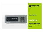
User’s Manual
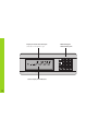
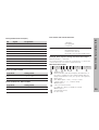
Measured Value Displays
6/ 2000
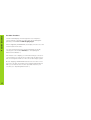
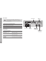
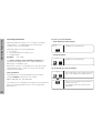
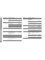
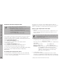
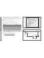
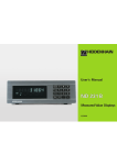
Display of actual value and input
(9 decades with algebraic sign)
REF
< = >
1
2 SET START PRINT inch
MIN
ACTL MAX DIFF
HEIDENHAIN
Status display with indicators
2
Numeric keypad
with decimal point
7
8
9
4
5
6
MOD
1
2
3
CL
0
.
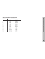
Key
Function
•
•
•
•
Set datum
Transfer input value
Set display to value from P79 (P80!)
Leave parameter list
Indicator
Meaning
REF
If the decimal point is also blinking:
Display is waiting for reference mark
traversing. If decimal point is not blinking:
Reference mark has been traversed—display
stores datum points in nonvolatile memory
Blinking: display is waiting for ENT or
CL to be depressed
inch
Position values in inches
• Select datum
• Page backwards in parameter list
MOD
•
•
•
•
•
Select parameter after switch-on
Page forward in parameter list
Start series of measurements 1)
Switch display for measurement series 1)
Start measured value output “PRINT”
•
•
•
•
•
Delete entry
Set display to zero (P80!)
CL plus MOD: select parameter list
CL plus number: select parameter
Delete parameter input and show
parameter number
1 /
2
PRINT
"Linear measurement”
Blinking: Display is waiting for ENT to
be pressed for data output
“Angular measurement”
Measured value output with MOD key
SET
Blinking: Display is waiting for input values
< / = / >
Sorting and tolerance checking:
measured value smaller than lower limit /
within the limits / greater than upper limit
MIN / MAX /
Series of measurements: Minimum /
maximum / greatest difference (MAX–MIN) /
current measured value
Blinking: Confirm selection or deselect
function
• Algebraic sign
• Reduce parameter value
• Decimal point
• Increase parameter value
DIFF / ACTL1)
START
1) Only in linear measurement mode.
Selected datum point
1)
Series of measurements is running
Blinking: Display is waiting for signal to
start series of measurements
3
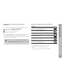
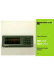
Items Supplied
Items supplied with ND 281 B
ND 281 B
Measured value display unit,
benchtop model
Encoder input
11 µAPP/1 VPP
Id. Nr. 344 996-xx
Power cord
3 m (9.9 ft)
User's Manual
ND 281B
Adhesive plug-in feet
For stacking ND 281B units
This manual is for the ND 281 B measured value
display with the following software number or higher:
349 797-01
4
The software number is indicated on a label on the
rear panel.
Installation and Specifications
Working with the ND Display Units
Encoders
6
Rear Panel, Accessories
Reference Marks
7
Mounting
19
Switch-On, Traversing the Reference Marks
8
Power Connection
20
Datum Setting
9
Linear/Angular Measuring Modes
21
22
24
Finding Minimum and MaximumValues 1)
17
Sorting and Tolerance Checking
13
Operating Parameters
List of Operating Parameters
Measured Value Output
14
Linear Encoders
28
Display Freeze
15
Angle Encoders
33
Error Messages
16
Nonlinear Axis Error Compensation
34
RS-232-C/V.24 Interface (X31)
38
Switching Inputs and Outputs EXT (X41)
43
Locking the Keypad
48
Displaying the Software Version
49
10
Distance-to-Go Mode
50
Specifications
Dimensions
51
52
1) Only in linear measurement mode
Contents
Contents
5
Position Encoders
Position Encoders
The ND 281 B display unit is designed for use with photoelectrical linear or angular encoders with sinusoidal signals:
primarily for HEIDENHAIN MT length gauges.
When shipped by HEIDENHAIN, the display units are set to the
linear measurement mode.
You can switch between the linear and angular modes by
entering the code number 415263 (see “Linear/Angular
Measurement Modes”).
On the back of the display you will find two flange sockets for
connecting the encoder: X1 for encoders with 11 µAPP sinusoidal current signals and X2 for 1 VPP sinusoidal voltage signals.
Before shipping, HEIDENHAIN activates the encoder connection X1 for 11 µAPP sinusoidal current signals. With parameter
P02 you can activate the encoder input that matches your
encoder (see “Operating Parameters”).
6
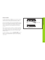
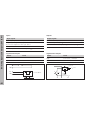
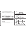
The MT length gauges have one reference mark. The scales of
other photoelectric linear or angular encoders can contain one
reference mark or many distance-coded reference marks.
If there is an interruption of power, the relationship between the
position of the length gauge and the displayed position value is
lost. The reference marks on the position encoders and the REF
reference mark evaluation feature enable the display unit to
quickly reestablish this relationship again when the power is
restored.
When a reference mark is crossed over, a signal is generated
which identifies that position as a reference point. At the same
time, the display unit restores the relationship between length
gauge position and display values which you last defined by
setting the datum.
Scale in
linear encoder
Distance-coded
reference marks
Reference Marks
Reference Marks
Reference mark
Reference marks on linear encoders
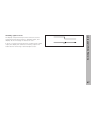
To restore the datum on scales with distance-coded reference
marks, you only need to traverse a maximum of 20 mm for
linear encoders, and 10° or 20° for angle encoders, depending
on the model.
7
0➤1
ENT...CL
Turn on the power.
(Switch located on rear panel.)
• ND 281 B appears for two seconds.
• ENT ... CL 1) appears.
• REF indicator is blinking.
Switch-on the reference mark evaluation
function.
• The position value that was last
assigned to the reference mark
position is displayed.
• REF indicator lights up.
• Decimal point is blinking.
5 , 6 9 7
⇔
Switch-On, Traversing the Reference Marks
Switch-On, Traversing the Reference Marks
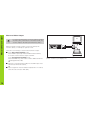
Cross over the reference mark.
Move the plunger until the display starts
counting and the decimal point stops blinking. The display is now ready for operation.
For automation purposes, crossing over the reference marks
and the display ENT ... CL can be disabled with parameter P82.
8
REF Mode
Crossing over the reference marks automatically switches the
display to REF mode: The last assignment of display values to
length gauge positions is stored in nonvolatile memory.
1)
Press the CL key if you choose not to traverse the reference
marks. Note that, in this case, the relationship between
length gauge position and display value will be lost if the
power is interrupted or if the unit is switched off.
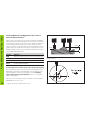
The datum setting procedure assigns a display value to a
known position. With the ND 200 series, you can set two
separate datum points.
There are several ways to set the datum:
• Enter a numerical value, or
• Transfer a value from an operating parameter
(see P79, P80), or
• By external signal
Z
?
?
?
Datum Setting
Datum Setting
?
?
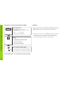
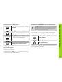
Select datum 1 or 2.
Without datum setting: unknown assignment of measured
values to positions
5
Enter numerical value (here, 5).
SET blinks.
Confirm the entered numerical value.
You can switch between datums 1 and 2 as desired. Datum 2
can be used, for example, for working with incremental dimensions.
When you switch back to datum 1, the display unit resumes
display of the encoder's actual position.
After datum setting: Assignment of measured values to
positions
9
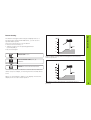
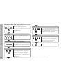
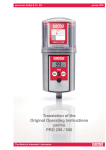
Finding Minimum and Maximum Values
Finding Minimum and Maximum Values from a
Series of Measurements 1)
After a series of measurements has been started, the display
transfers the first measured value to the memory for minimum
and maximum values. Every 0.55 ms, the display compares the
current measured value with the memory contents: A new
value is stored if it is greater than the stored maximum value or
smaller than the stored minimum value. At the same time, the
display calculates and stores the difference DIFF between the
current MIN and MAX values.
Display
Meaning
MIN
Minimum value from the series of measurements
MAX
Maximum value from the series of measurements
DIFF
Difference MAX – MIN
ACTL
Current measured value
MAX
ACTL
DIFF
MIN
Series of measurements: The MIN, MAX and DIFF values of an
uneven surface
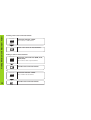
Starting the measurement series and selecting the display
You can start the series of measurements either by pressing
MOD and selecting the desired display— as described on the
following pages— or by external signal over the switching
inputs at the D-sub connection EXT (X41, see “Switching
Inputs and Outputs”).
When a series of measurements is started, the internal MIN/
MAX/DIFF memory is reset.
10
1) Only in the linear measurement mode.
Example: Measurement series for determining eccentricity e
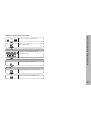
Repeatedly
MOD
MAX
Switching between MIN, MAX, DIFF and ACTL displays
It is not possible to switch between the displays as
described below if the switching input for external
control of the series of measurements (pin 6 on
D-sub connection EXT) is active.
Select the display for a series of measurements.
The selected indicator blinks (here, MAX).
Confirm selection.
As an alternative, you can select the display with operating
parameter P21 (see “Operating Parameters”).
Repeatedly
Repeatedly
... until the START indicator blinks.
MOD
MOD
Select the new display of a series of
measurements.
The selected indicator blinks (here, MIN).
MIN
START
Start the series of measurements.
Indicator preselection
Confirm the change.
The display now shows the smallest value measured during the
current series of measurements.
Finding Minimum and Maximum Values
Starting a series of measurements
Press MOD to start the series of measurements and select the
display with the indicators.
Operating parameter P86 allows you to define which indicator
is displayed first when MOD is pressed.
11
Finding Minimum and Maximum Values
Starting a new series of measurements
Repeatedly
MOD
Select the indicator START.
The indicator START blinks.
START
Start a new series of measurements.
Ending a series of measurements
Repeatedly
MOD
Select the active indicator (MIN, ACTL,
MAX, DIFF).
The indicator that lit up last blinks.
End the series of measurements.
or
Repeatedly
MOD
Select the indicator START.
The START indicator blinks.
START
12
End the series of measurements.
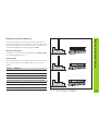
In the sorting and tolerance checking mode, the display unit
compares the displayed value with the programmed upper and
lower sorting limits. The sorting and tolerance checking mode is
enabled and disabled with operating parameter P17.
Entering sorting limits
Part 1
Sorting limits are entered in operating parameters P18 and P19
(see “Operating Parameters”).
Accept
Sorting signals
The indicators and switching outputs at D-sub connection EXT
(see section on X41) sort the display value into one of three
classes.
Part 2
Display
Sorting and Tolerance Checking
Sorting and Tolerance Checking
Meaning
Rework
=
Measured value is within sorting limits
<
Measured value is smaller than lower sorting limit
>
Measured value is greater than upper sorting limit
Operating parameters for sorting and tolerance checking
P17 SORT
Sorting ON/OFF
P18 L.LIMIT
Lower sorting limit
P19 U.LIMIT
Upper sorting limit
Part 3
Reject
Example: Upper sorting limit = 26.02 mm
Lower sorting limit = 26.00 mm
13
Measured Value Output
14
Measured Value Output
PC
For technical information on the RS-232-C/V.24 data
interface (X31), information on the data format, etc.,
see the chapter “RS-232-C/V.24 Interface (X31).”
Measured values can be output over the RS-232-C/V.24
interface (X31), for example to a printer or PC.
REF
<
=
1
2
>
MIN
SET
START
ACTL
PRINT
MAX
in.
DIFF
MOD
CL
7
8
9
4
5
6
1
2
3
0
.
–
HEIDENHAIN
There are several ways to start measured value output:
➤ In the linear measurement mode:
Press MOD repeatedly until the PRINT indicator blinks,
then start measured value output with ENT.
In the angular measurement mode:
Press the MOD key (this feature can be disabled with the
operating parameter 86).
or
➤ Input the command STX (Ctrl B) over the RXD input of the
RS-232-C/V.24 interface (X31);
or
➤ Input a signal for measured data output (Pulse or Contact)
at the D-sub connection EXT (X41).
The RS-232-C/V.24 interface (X31) enables you to connect a
printer or a PC to your display unit
With the latch command, the display can be stopped for any
period of time. The internal counter remains active. Parameter
P23 selects the “display freeze” mode and offers three
settings:
• Concurrent display, no display freeze— the display value
is the current measured value.
• Frozen display— display value is frozen and is updated with
each signal for measured value output.
• Frozen/concurrent display— display remains frozen as
long as the latch signal is present; after the signal, the
display resumes continuous display of the current measured values.
Display Freeze
Display Freeze
Position
Latch
signal
Frozen
display
Frozen/
concurrent
display
15
Error Messages
Error Messages
Display
Effect/Cause
RS232 FAST
Command for measured value
output followed too quickly by
another. 1)
SIGNAL
Encoder signal is too weak.
The scale may be contaminated. 1)
DSR.MISSING
The connected device has not sent
a DSR signal. 1)
REF. ERR.
The spacing of the reference marks
as defined in P43 is not the actual
spacing. 1)
FORMAT ERR.
Data format, baud rate, etc. do not
match. 1)
FREQUENCY
Input frequency too high for encoder
input. Traversing speed may be too
fast. 1)
MEMORY ERR.
Checksum error: Check the datum,
operating parameters and compensation values for nonlinear axis error
compensation. If this error recurs,
contact your service agency!
1) These errors are important for the attached device. The
error signal (pin 19) at D-sub connection EXT is active.
16
Other Error Displays
If “OVERFLOW” appears, the measured value is too large or
too small:
➤ Set a new datum.
or
➤ Traverse back.
If all sorting signals light up, the upper sorting limit is smaller
than the lower limit:
➤ Change operating parameters P18 and/or P19.
To clear error messages:
Once you have removed the cause of the error:
➤ Clear the error message with the CL key.
Ports X1, X2, X31 and X41 comply with the
recommendations in EN 50 178 for separation
from line power.
Encoder input X1
HEIDENHAIN flange socket
Input signals
Maximum encoder cable length
Maximum input frequency
9-pin
11 µAPP
30 m (98.5 ft)
Rear Panel, Accessories
Rear Panel
100 kHz
Encoder input X2
HEIDENHAIN flange socket
Input signals
Maximum encoder cable length
Maximum input frequency
12-pin
1 VPP
60 m (197 ft)
500 kHz
17
Rear Panel, Accessories
Rear Panel
Data interface
Ports X1 X2, X31 and X41 comply with the
recommendations in EN 50 178 for separation
from line power.
RS-232-C/V.24 data interface (X31)
25-pin D-sub connection (female)
Switching inputs and outputs EXT (X41)
25-pin D-sub connection (male)
Power switch
Accessories
Connecting elements
18
D-sub
connection
Connector (female)
25-pin for D-sub connection X41
Id. Nr. 249 154 ZY
Connector (male)
25-pin for D-sub connection X31
Id. Nr. 245 739 ZY
Data interface cable,
complete
3 m (9.9 ft), 25-pin for D-sub connection X31, Id. Nr. 274 545-01
Ground
connection
Input X1 for one
HEIDENHAIN
11 µAPP encoder
Input X2 for one
HEIDENHAIN
1 VPP encoder
172 ± 0.2
6.77 ± .008"
140 ± 0.2
5.51 ± .008"
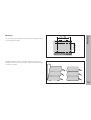
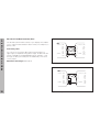
You can fasten the ND 281 B from below by using M4 screws
(see illustration at right).
Mounting
Mounting
Hole positions for mounting the ND display unit
ND 281 B display units are stackable. Adhesive plug-in feet
(supplied with your unit) prevent the stacked units from being
moved out of place.
15°
Alternatives of stacking the display units
19
Power Connection
Power Connection
The rear panel of the ND 281 B contains a connecting jack for
a power cord with Euro connector (power cord supplied with
the delivery).
Minimum cross section of the power cord: 0.75 mm2
Power supply: 100 Vac to 240 Vac (–15% to +10%)
Power supply: 50 Hz to 60 Hz (± 2 Hz)
A voltage selector is therefore not necessary.
Danger of electrical shock!
Unplug the power cord before opening the
housing. Connect the grounding conductor.
Do not interrupt the grounding conductor.
Danger to internal components!
Do not engage or disengage any connections
while the unit is under power. Use only original
replacement fuses.
To increase noise immunity, connect the ground
terminal on the rear panel to the central ground
point of the machine.
(Minimum cross-section: 6 mm2)
20
You can select the linear measuring mode or angular
measuring mode by entering the code number 415263:
➤ Select the user parameter P00 CODE
(see “Operating Parameters“).
➤ Enter the code number 415263.
➤ Confirm your entry with ENT.
➤ With the “.” or “–” key, select the ND LENGTH or
ND ANGLE mode, respectively.
➤ Confirm your selection with ENT.
➤ The display unit resets itself.
Linear/Angular Measuring Modes
Linear/Angular Measuring Modes
➤ For further procedure, see “Switch-on, Traversing the
Reference Marks.”
21
Operating Parameters
Operating Parameters
To access a user parameter ...
... after switching on the display:
Operating parameters allow you to modify the operating
characteristics of your ND display unit and define the
evaluation of the encoder signals.
Operating parameters are designated by:
•
•
•
the letter P,
a two-digit parameter number, and
an abbreviation.
Example:
While ENT ... CL is
displayed:
Display first user parameter.
MOD
... during operation:
P01 INCH
Together:
The factory settings of the operating parameters are
indicated in the parameter list (see “List of Operating
Parameters”) in boldface type.
Parameters consist of “user parameters” and “protected
operating parameters,” which can only be accessed by
entering a code number.
User parameters
User parameters are operating parameters that can be
changed without entering the code number:
Display first user parameter.
MOD
To go directly to a user parameter:
Together:
Press and hold CL while entering the first
digit of the parameter number (here, 1).
P00 to P30, P50, P51, P79, P86, P98
The functions of the individual user parameters are detailed in
the list of operating parameters (see “List of Operating
Parameters”).
22
Enter the second digit of the parameter
number (here, 9).
The display shows the selected user
parameter.
Functions for changing the operating parameters
Function
If you wish to change protected operating parameters, you
must first enter the code number 95 148:
➤ Select the user parameter P00 CODE.
➤ Enter the code number 9 51 48.
➤ Confirm entry with ENT.
Page forward
in the list of operating parameters
Page backward
in the list of operating parameters
Reduce parameter value
Parameter P30 appears on the display. By paging through the
list of operating parameters you can display— and, if
necessary, change— each protected operating parameter and,
of course, each user parameter.
Increase parameter value
Key
MOD
Operating Parameters
Code number for changing protected operating
parameters
Correct entry and
display parameter designations
Once you have entered the code number, the
protected operating parameters remain accessible
until the display unit is switched off.
Confirm change or numerical entry,
leave list of operating parameters
A changed parameter is stored as soon as you
•
•
leave the list of operating parameters
or
page forward or backward after the change.
23
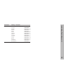
List of Operating Parameters
List of Operating Parameters
Parameter
P00 CODE
P01
Settings / Function
Enter a code number:
9 51 48: To change the protected
operating parameters
41 52 63: To select the linear or angular
measurement mode
10 52 96: Nonlinear axis error
compensation
24 65 84: To lock the keyboard
66 55 44: To show the software version
24 65 82: Distance-to-go display
Units of measurement 1)
Display in millimeters
Display in inches
P02 X1/X2
Select an encoder input
Signals at X1
Signals at X2
P08 DISPL.
P09 ANGLE
24
1)
P11 SCL
Scaling factor 1)
Scaling factor on
SCALING ON
Scaling factor off
SCALNG. OFF
Scaling factor 1)
Enter a numerical value
0.100000 < P12 < 9.999999
Default setting: 1.000000
P17 SORT
Sorting and tolerance checking
Sorting and tol. checking ON
SORT ON
Sorting and tol. checking OFF
SORT OFF
P18 L.LIMIT
Lower limit for sorting
P19 U.LIMIT
Upper limit for sorting
P21 SERIES
Display for series of measurements 1)
OFF
MIN
MAX
ACTL
DIFF
P23 DISPL.
INCH
11 µAPP
Settings / Function
P12 SCL
MM
1 VPP
Deg., minutes, seconds
DEG.MIN.SEC.
Display stop for measured value output
Concurrent display, no display freeze;
the display value is the current actual
value
DISPL. ACTL.
Angle display 2)
+/- 180°
+/- 180 DEG.
Frozen display; hold display until next
measured value output
DISPL. HOLD
2)
Display mode
Decimal Degrees
DEC. DEGREE
+/- ∞
ENDLESS
360°
360 DEG.
Only in linear measurement mode.
in angular measurement mode.
2) Only
Parameter
Frozen/concurrent display; freeze display
as long as Pulse/Contact for measured
value output is present
DISPL. STOP
P30 DIR
Settings/ Function
Parameter
Counting direction
Positive counting direction with
positive direction of traverse DIRECT. POS
P40 COMP.
P33 COUNT
Signal period 1) of encoder
0.000 000 01 < P31 < 99 999.9999
Default setting: 10 µm
Counting mode 1)
0-1-2-3-4-5-6-7-8-9
COUNT 0-1
0-2-4-6-8
COUNT 0-2
0-5
COUNT 0-5
P36 SP/R
Signal periods per revolution 2)
1 < P36 < 999 999
Default setting: 36 000
P37 COUNT.
Counting mode 2)
0-1-2-3-4-5-6-7-8-9
COUNT 0-1
0-2-4-6-8
COUNT 0-2
0-5
COUNT 0-5
P38 DP POS
1)
Decimal places 3)
1/2/3/4/5/6
(up to 8 for inch display)
Only in linear measurement mode.
2) Only in angular measurement mode.
3) Depends on signal period (P31) and measuring unit (P01)
Select encoder compensation
No compensation
COMP. OFF
Nonlinear: up to 64 compensation points for
linear encoders, up to 72 for angle encoders
(fixed spacing of 5 deg.)
NONL. COMP
Negative counting direction with
positive direction of traverse DIRECT. NEG
P31 S. PER.
Settings/ Function
COMP. ON 1)
Linear compensation
P41 L.COMP.
Linear error compensation 1)
–
99 999.9 < P41 < + 99 999.9 [µm/m]
Default setting: 0
Example: Find input value for P41
Displayed measuring length ............. La = 620.000 mm
Actual length (measured, e.g.
with the VM 101 comparator
system from HEIDENHAIN) .............. Lt = 619.877 mm
Length difference ............................. ∆L = Lt – La = – 123 µm
List of Operating Parameters
Parameter
Compensation factor k (= P41):
k = ∆L / La = – 123 µm / 0.62 m ........ k = – 198.4 [µm/m]
P43 REF
Reference marks
One reference mark
SINGLE REF.
Distance-coded with 500 • SP
(SP: signal period)
500 SP
Distance-coded with 1000 • SP
(e.g. for HEIDENHAIN LS ...C)
1000 SP
Distance-coded with 2000 • SP
2000 SP
Distance-coded with 5000 • SP
5000 SP
25
List of Operating Parameters
Parameter
P44 REF
Parameter
Reference mark evaluation
Evaluate the reference mark
P80 ENT-CL
REF. ON
Do not evaluate the reference
mark
P45 ALARM
REF. OFF
Encoder monitoring
No monitoring
ALARM OFF
Monitor the frequency
FREQUENCY
Monitor contamination
CONTAMINAT.
P50 RS232
Baud rate
110 / 150 / 300 / 600 / 1200 /
2400 / 4800 / 9600 / 19 200 /
38 400 baud
Additional blank lines
during data output
0 ≤ P51 ≤ 99
Default setting: 1
P62 A1
Trigger limit 1
P63 A2
Trigger limit 2
P79 PRESET
Value for datum point
Enter numerical value for
datum setting over switching input
or with ENT key
Set display
No set/Set with
CL/ENT
CL-ENT OFF
Zero reset with CL
setting disabled with ENT
CL......ON
P82 DISPL.ON Message after switch-on
ENT...CL message
P85 EXT.REF
MESSAGE ON
No message
MESSG. OFF
External REF
REF over D-sub port EXT
EXT.REF ON
No REF over D-sub port EXT EXT.REF OFF
P86 MOD
BK LINE 1
Settings / Function
Zero reset with CL and set with
ENT to value selected in P79
CL-ENT ON
Contamination + frequency FRQ. + CONT.
P51 RS232
26
Settings / Function
In the linear measurement mode
First indicator after pressing MOD
START
PRINT
MIN
ACTL
MAX
DIFF
In the angular measurement mode
PRINT via MOD disabled
PRINT OFF
PRINT via MOD enabled
PRINT ON
P98 LANGUA.
Settings / Function
Conversational language
German
English
French
Italian
Dutch
Spanish
Danish
Swedish
Finnish
Czech
Polish
Hungarian
Portuguese
LANGUAGE
LANGUAGE
LANGUAGE
LANGUAGE
LANGUAGE
LANGUAGE
LANGUAGE
LANGUAGE
LANGUAGE
LANGUAGE
LANGUAGE
LANGUAGE
LANGUAGE
D
GB
F
I
NL
E
DK
S
FI
CZ
PL
H
P
List of Operating Parameters
Parameter
27
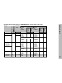
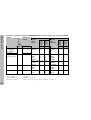
Linear Encoders
Linear Encoders
The ND 281 B display unit is designed for use together with
photoelectrical encoders with sinusoidal signals— 11 µAPP or
1 VPP.
Display step with linear encoders
You can select a specific display step by adapting the
following operating parameters:
• Signal period (P31)
• Counting mode (P33)
• Decimal places (P38)
Example
Linear encoder with a signal period of 10 µm
Desired display step ................. 0.000 5 mm
Signal period (P31) ................... 10
Counting mode (P33) ............... 5
Decimal places (P38) ................ 4
The tables on the following pages will help you to select the
appropriate parameter settings.
28
4
MT xx
10
LS 303/303C
LS 603/603C
20
Decimal
places
Display
step
in inches
P 33
P 38
0.0005
5
4
0.0002
2
4
0.0001
1
4
Single
0.00005
5
5
Recommd. only for LIP 401
0.00002
2
5
0.00001
1
5
0.000005
5
6
Single/5000 0.001
1
3
5
4
0.0005
0.0002
2
4
1
4
0.0001
0.00005
5
5
Single
Recommd. only for LIP 101
0.00002
2
5
0.00001
1
5
Single
0.0005
5
4
0.0002
2
4
0.0001
1
4
Single/1000 0.01
1
2
0.005
5
3
0.00002
0.00001
0.000005
0.000002
P 33
2
1
5
2
P 38
5
5
6
6
0.000001
0.0000005
0.0000002
0.00005
0.00002
0.00001
0.000005
0.000002
1
5
2
5
2
1
5
2
6
7
7
5
5
5
6
6
0.000001
0.0000005
0.00002
0.00001
0.000005
0.0005
0.0002
1
5
2
1
5
5
2
6
7
5
5
6
4
4
Linear Encoders
P 43
Single
Inches
Display
step
in mm
Decimal
places
LF 103/103C
LF 401/401C
LIF 101/101C
LIP 501/501C
LIP 101
2
Millimeters
Count
mode
CT
MT xx01
LIP 401A/401R
Reference
marks
Count
mode
Model
Signal periods
in µm
P31
Recommended parameter settings for HEIDENHAIN linear encoders with 11 µAPP signals
29
30
Display
step
in inches
P 43
Single/1000 0.001
0.0005
P 33
1
5
P 38
3
4
Single/2000 0.005
5
3
0.002
2
3
0.001
1
3
0.0005
5
4
Recommd. only for LB 302
0.0002
2
4
0.0001
1
4
100
Single/1000 0.005
5
3
0.002
2
3
0.001
1
3
12800 Single
0.1
1
1
0.05
5
2
40
Decimal
places
LIM 102
Inches
Display
step
in mm
Count
mode
LB 301/301C
20
Millimeters
Decimal
places
LS 106/106C
LS 406/406C
LS 706/706C
ST 1201
LB 302/302C
LIDA 10x/10xC
Reference
marks
Count
mode
Model
Signal period
in µm
P31
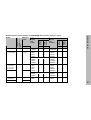
Linear Encoders
Recommd. parameter settings for HEIDENHAIN linear encoders with 11 µAPP signals (continued)
0.00005
0.00002
P 33
5
2
P 38
5
5
0.0002
0.0001
0.00005
0.00002
2
1
5
2
4
4
5
5
0.000001
0.0000005
0.0002
0.0001
0.00005
0.005
0.002
1
5
2
1
5
5
2
5
6
4
4
5
3
3
Example
Your encoder:
Desired display step:
MT 101
0.0005 mm (0,5 µm)
Parameter settings:
P01 = mm, P43 = single, P31 = 10, P33 = 5, P38 = 4
2
LF 183/183C
LF 481/481C
LIF 181/181C
LIP 581/581C
VM 182
LS 186/186C
LS 486/486C
ST 1281
4
20
Decimal
places
Display
step
in inches
P 33
P 38
0.000002
2
6
0.000001
1
6
Single
0.0005
5
4
-/single
0.0002
2
4
0.0001
1
4
0.00005
5
5
Recommd. only for LIP 401
0.00002
2
5
0.00001
1
5
0.000005
5
6
Single/5000 0.001
1
3
0.0005
5
4
0.0002
2
4
0.0001
1
4
0.00005
5
5
Recommd. only for VM 182
0.00002
2
5
0.00001
1
5
Single/1000 0.001
1
3
0.0005
5
4
-
0.0000001
0.00000005
0.00002
0.00001
0.000005
0.000002
P 33
1
5
2
1
5
2
P 38
7
8
5
5
6
6
0.000001
0.0000005
0.0000002
0.00005
0.00002
0.00001
0.000005
0.000002
1
5
2
5
2
1
5
2
6
7
7
5
5
5
6
6
0.000001
0.0000005
0.00005
0.00002
1
5
5
2
6
7
5
5
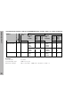
Linear Encoders
MT xx81
LIP 481A/481R
P 43
-
Inches
Display
step
in mm
Decimal
places
0.128
Millimeters
Count
mode
LIP 382
Reference
marks
Count
mode
Model
Signal period
in µm
P31
Recommended parameter settings for HEIDENHAIN linear encoders with 1 VPP signals
31
32
100
Display
step
in inches
Decimal
places
Inch
Display
step
in mm
P 43
P 33
P 38
Single/2000 0.005
5
3
0.002
2
3
0.001
1
3
0.0005
5
4
Recommd. only for LB 382
0.0002
2
4
0.0001
1
4
Single/1000 0.005
5
3
0.002
2
3
0.001
1
3
Decimal
places
LB 381/381C
40
Millimeters
Count
mode
LB 382/382C
LIDA 18x/18xC
Reference
marks
Count
mode
Model
Signal period
in µm
P31
Linear Encoders
Recommended parameter settings for HEIDENHAIN linear encoders with 1 VPP signals (continued)
0.0002
0.0001
0.00005
0.00002
P 33
2
1
5
2
P 38
4
4
5
5
0.00001
0.000005
0.0002
0.0001
0.00005
1
5
2
1
5
5
6
4
4
5
Example
Your encoder:
Desired display step:
LS 186 C
0.001 mm (1 µm)
Parameter settings:
P01 = mm, P43 = 1 000, P31 = 20, P33 = 1, P38 = 3
ROD 450
ROD 456
/
/ ROD 486
/ ROD 1080
ROD 250 C / ROD 280 C
RON 255 C / RON 285 C
3600
Display
step
P43
One
Single
P37
P38
0.01°
0.005°
0.001°
1
5
1
3
3
9000
Dist.coded
500
0.005°
0.001°
5
1
3
3
ROD 250 C
ROD 255 C
ROD 700 C
RON 705 C
RON 706 C
/ ROD 280 C
/ RON 285 C
/ ROD 780 C
/ RON 785 C
/ RON 786 C
18 000
Dist.coded
1000
0.001°
0.0005°
0.0001°
1
5
1
3
4
4
RON 905
/
36 000
One
Single
0.0001°
1
4
ROD 800 C / ROD 880 C
ROD 806 C / ROD 886 C
36 000
Dist.coded
1000
0.0001°
1
4
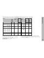
Example:
Set parameters for any encoder
Angle encoder, e.g. with line count s = 18 000 (P36)
Desired display step, e.g. a = 0.001°
Counting mode P37 = 1 (display counts 1, 2, 3, ...)
Decimal places of a: P38 = 3
Angle Encoders
Reference
marks
Count
mode
Signal periods
per revolution
P36
Model
Decimal
places
Recommended parameter settings for HEIDENHAIN angle encoders with 11 µAPP / 1 VPP signals
Convert decimal degrees into degrees, minutes, seconds
1 degree (1°) = 60 minutes (60'); 1 minute (1') = 60 seconds (60")
1 second (1") ≈ 0.000278°
33
Nonlinear Axis Error Compensation
Nonlinear Axis Error Compensation
If you want to use the nonlinear axis error
compensation feature, you must:
• Activate the feature with operating parameter
40 (see “Operating Parameters”),
• Traverse the reference marks after switching
on the display unit,
• enter a compensation value table
Your machine may have a nonlinear axis error due to factors
such as axis sag or leadscrew errors. Such deviations are
usually measured with a comparator measuring system (such
as the HEIDENHAIN VM 101).
In the linear measurement mode:
You can make a compensation value table with 64
compensation values.
In the angular measurement mode:
You can make a compensation value table with 72
compensation points (point spacing: 5 degrees).
The letter “R” at the left of the display indicates that the
displayed position value is given with respect to the reference
mark. If “R” blinks, you must traverse the reference mark.
Entries in the compensation value table
• Datum 1):
Here you enter the point at which the compensation is to
begin. This point indicates the absolute distance to the
reference point.
Do not change the datum after measuring the axis
error and before entering the axis error into the
compensation table.
•
Spacing of the compensation points 1):
The spacing of the compensation points is expressed as:
Spacing = 2 x [µm].
Enter the value of the exponent x in into the compensation
value table.
Minimum input value:
6 (= 0.064 mm)
Maximum input value:
20 (= 1048.576 mm)
Example: 900 mm traverse with 15 compensation points
==> 60.000 mm spacing between points.
16
Nearest power of two: 2 = 65.536 mm (see
“Table for determining the point spacing”)
Input value in the table: 16
•
Compensation value:
You enter the measured compensation value (in millimeters) for the displayed compensation point. Compensation point 0 always has the value 0 and cannot be changed.
You select the compensation table through P00 CODE and by
entering the code number 10 52 96 (see Operating
Parameters).
Ascertaining the compensation values
To ascertain the compensation values (e.g. with a VM 101)
you must select the compensation table and then press the
“–” key to select the REF display.
34
1)
Only in the linear measurement mode
Exponent
Point spacing
in mm
in inches
6
7
8
9
10
11
12
13
14
15
16
17
18
19
20
0.064
0.128
0.256
0.512
1.024
2.048
4.016
8.192
16.384
32.768
65.536
131.072
262.144
524.288
1048.576
0.0023“
0.0050“
0.0100“
0.0200“
0.0403“
0.0806“
0.1581“
0.3225“
0.6450“
1.290“
2.580“
5.160“
10.32“
20.64“
41.25“
Nonlinear Axis Error Compensation
Table for determining the point spacing
35
Nonlinear Axis Error Compensation
Selecting the compensation table, entering an axis correction
together
with
Select the operating parameters.
COMP. NR. 01
Select P00 CODE.
2x
MOD
Enter the associated compensation value,
e.g. 0.01 mm. Press MOD twice to
select COMP. NR. 02. (You cannot enter
any values in the POS. NR. 02 box).
P00 CODE
Enter the code number 10 52 96,
confirm with ENT.
COMP. NR. 02
2x
DATUM (shown for approx. two seconds) 1)
Enter the active datum for the error on
MOD
the axis to be confirmed, e.g. 27 mm.
Press MOD to select the next input box.
SPACING
4x
36
MOD
MOD
MOD
Enter all further compensation points.
If you want so select a compensation
point directly, press CL and
simultaneously enter the desired
compensation point number.
Conclude entry.
1)
Enter the spacing of the compensation
points on the axis to be corrected, for
10
example 2 µm (equals 1.024 mm).
Press MOD four times to select COMP.
NR. 01. (You cannot enter values in the
POS. NR. 00, COMP. NR. 00 and POS.
NR. 01 boxes.)
1)
Only in the linear measurement mode
together
with
MOD
Select the operating parameters.
Select P00 CODE.
P00 CODE
Enter the code number 10 52 96,
confirm with ENT.
DATUM
Select the “delete” function.
Nonlinear Axis Error Compensation
Deleting a compensation value table
DELETE
Confirm with ENT or cancel with CL.
Exit the compensation table mode.
37
RS-232-C/V.24 Data Interface (X31)
RS-232-C/V.24 Data Interface (X31)
The RS-232-C/V.24 interface (X31) of your display unit enables
you to output measured data in ASCII format, for example to a
printer or PC.
ND
CHASSIS GND
1
1 CHASSIS GND
TXD
2
2
TXD
RXD
RTS
CTS
3
4
5
3
4
5
RXD
RTS
CTS
DSR
GND
6
7
6
7 SIGNAL
DSR
GND
Connecting cable
You can use a connecting cable with full wiring (figure at
upper right) or simplified wiring (below right). A cable with full
wiring is available from HEIDENHAIN (Id. Nr. 274 545-...). On
this type of cable, pin 6 and pin 8 are additionally connected
over a jumper.
SIGNAL
DTR 20
DTR
20
Maximum cable length: 20 m (66 ft)
Full wiring
ND
CHASSIS GND
1
1 CHASSIS GND
TXD
2
2
TXD
RXD
RTS
CTS
3
4
5
3
4
5
RXD
RTS
CTS
DSR
GND
6
7
6
7 SIGNAL
DSR
GND
SIGNAL
DTR 20
38
Simplified wiring
20
DTR
Data format and control characters
Data format
1 start bit
7 data bits
Even parity bit
2 stop bits
Control characters
Request to send
Call measured value: STX (Ctrl B)
Interrupt DC3 (Ctrl S)
Continue DC1 (Ctrl Q)
CTS
Clear to send
Interrogate error message: ENQ (Ctrl E)
6
DSR
Data set ready
7
SIGN. GND
Signal ground
8 to 19
–
Not assigned
20
DTR
Data terminal ready
21 to 25
–
Not assigned
Pin
Signal
Assignment
1
CHASSIS GND
Chassis ground
2
TXD
Transmitted data
3
RXD
Received data
4
RTS
5
Levels for TXD and RXD
Logic level
Voltage level
Active
– 3 V to – 15 V
Not active
+ 3 V to +15 V
Levels for RTS, CTS, DSR and DTR
Logic level
Voltage level
Active
+ 3 V to + 15 V
Not active
– 3 V to – 15 V
Example: Data sequence during measured value output
Measured value = – 5.23 mm
The measured value is within the sorting limits ( = ) and is the
current value ( A ) of a series of measurements.
Measured value output
1
1
2
3
4
5
6
7
8
5 . 2 3
2
3
4
=
A
< C R >
5
6
7
< L F >
8
Algebraic sign
Numerical value with decimal point (10 characters on
the whole, leading zeros are output as blank spaces.)
(Angle measurement “min, sec” up to 3 dec. spaces.)
Blank space
Unit: Blank space = mm; " = inch; ? = fault
Sorting status (<, >, =; ? if P18 > P19)
or blank space
Series of measurements
(S = MIN; A = ACTL; G = MAX; D = DIFF)
or blank space
CR (carriage return)
LF (line feed)
RS-232-C/V.24 Data Interface (X31)
Pin layout RS-232-C/V.24 (X31)
39
RS-232-C/V.24 Data Interface (X31)
40
Operating parameters for measured value output
Parameter
Measured value output via PRINT function
In the linear measurement mode
Press MOD repeatedly until the indicator PRINT blinks.
Start the measured value output with ENT.
In the angular measurement mode
Press MOD (this feature can be disabled with operating
parameter 86).
Function
P50 RS232
Baud rate
P51 RS232
Number of additional blank lines for
measured value output
Duration of measured value transfer
Display freeze during measured value output
tD =
In operating parameter P23, you can specify how the
measured value output signal will affect the display unit.
Display freeze during measured value output
Concurrent display, no display freeze: The
display value is the current measured value
P23
DISPL. ACTL.
Frozen display: Display is stopped
(frozen) and updated by every
measured value output signal
DISPL. HOLD
Frozen/concurrent display: Display is
frozen as long as a measured value output
signal is present
DISPL. STOP
187 + (11 • number of blank lines)
[ s]
baud rate
Indicator preselection (linear measurement mode)
Operating parameter P86 allows you to define which indicator
is displayed first when MOD is pressed.
To start measured value output through the EXT interface
(X41) you can either:
➤ Close the “Contact” input (pin 23 on X41) against 0 V,
for example with a simple switch (make contact);
or
➤ Close the “Pulse” input (pin 22 on X41) against 0 V,
for example by triggering the input with a TTL logic
device (such as SN74LSxx).
EXT(X41)
Pin 23
Pin 1(0V)
EXT(X41)
Pin 22
Pin 1(0V)
Characteristic times for measured value output
Process
Time
Minimum duration of “Contact” signal
te ≥ 7 ms
Minimum duration of “Pulse” signal
te ≥ 1.5 µs
Storage delay after “Contact”
t1 ≤ 5 ms
Storage delay after “Pulse”
t1 ≤ 1 µs
Measured value output after
t2 ≤ 57 ms
Regeneration time
t3 ≥ 0
Triggering the “Contact” and “Pulse” inputs at D-sub
connection EXT (X41)
te
te
RS-232-C/V.24 Data Interface (X31)
Measured value output after signal through the “Contact”
or “Pulse” inputs
t1
t3
t2
Duration of measured value transfer
tD =
187 + (11 • number of blank lines)
[s]
baud rate
tD
Signal transit times for measured value output after “Pulse”
or “Contact”
41
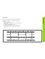
RS-232-C/V.24 Data Interface (X31)
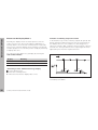
Measured value output after “STX” signal (Ctrl B)
10
20
30
40
50
60
70
80
90
100
110
120
130
If the display unit receives the control character STX (Ctrl B)
over the RS-232-C/V.24 interface (X31), it outputs the current
measured value over the interface.
➤ Transfer the control character Ctrl B over the RXD line of
the RS-232-C/V.24 interface (X31).
Characteristic times for measured value output
Process
Time
Storage delay
t1 ≤ 1 ms
Measured value output after
t2 ≤ 50 ms
Regeneration time
t3 ≥ 0
These times are prolonged if functions are active
(for example, series of measurements with DIFF
value display).
Duration of measured value transfer
tD =
187 + (11 • number of blank lines)
[s]
baud rate
L%=18
CLS
PRINT "V.24/RS-232-C"
OPEN "COM1:9600,E,7" AS#1
PRINT #1, CHR$ (2);
IF INKEY$<>""THEN 130
C%=LOC(1)
IF C%<L%THEN 60
X$=INPUT$(L%,#1)
LOCATE 9,1
PRINT X$;
GOTO 50
END
BASIC program for measured value output with “Ctrl B”
Ctrl B
Ctrl B
t1
t3
t2
tD
42
Propagation times for measured value output after “Ctrl B”
Danger to internal components!
Voltage sources for external circuitry must conform
to the recommendations in EN 50 178 for lowvoltage electrical separation. Connect inductive
loads only with a quenching diode parallel to the
inductance.
Inputs at D-sub connection EXT (X41)
Pin
Function
1, 10
0V
2
Reset display to zero, clear error message
3
Set display to the value selected in P79
4
Ignore reference mark signals
5
Start series of measurements 1)
6
Externally select display value for series of
measurements 1)
7
Display MIN value of series of measurements 1)
8
Display MAX value of series of measurements 1)
Function
9
Display difference MAX – MIN 1)
14
Display value is zero
22
Pulse: Output measured value
15
Measured value ≥ trigger limit A1 (P62)
23
Contact: Output measured value
16
Measured value ≥ trigger limit A2 (P63)
25
17
Measured value < lower sorting limit (P18)
Enable or disable REF mode
(current REF status is changed)
18
Measured value > upper sorting limit (P19)
12, 13, 24
Do not assign
19
Error (see “Error Messages”)
11, 20, 21
Vacant
Only use shielded cable!
Connect the shield to the connector housing.
Outputs at D-sub connection EXT (X41)
Pin
Switching Inputs and Outputs EXT (X41)
Switching Inputs and Outputs EXT (X41)
Special case: Display current measured value ACTL
If you wish to display the current measured value ACTL of a
series of measurements, note for inputs 7, 8 and 9:
Either none or more than one of these inputs must be active.
1)
Only in the linear measurement mode
43
Switching Inputs and Outputs EXT (X41)
Inputs
Outputs
Input signals
Output signals
Internal pull-up resistor 1 kΩ, active with low level
Open collector outputs, active with low level
Trigger by making contact against 0 V or
by low level signal over TTL logic device
Delay until signal output: td ≤ 30 ms
Signal duration of zero signal, trigger limit A1, A2: t0 ≥ 180 ms
Delay for set/zero reset: td ≤ 2 ms
Minimum pulse duration for all signals: tmin ≥ 30 ms
Signal level of inputs
Status
Signal level of outputs
Level
Status
Level
High
+ 3.9 V ≤ U ≤ + 15 V
High
U ≤ + 32 V; I ≤ 10 µA
Low
– 0.5 V ≤ U ≤ + 0.9 V; I ≤ 6 mA
Low
U ≤ + 0.4 V; I ≤ 100 mA
E
I ≤ 100 mA
0V
+ UB ≤ 32 V
C
E
tmin ≥ 30 ms
0V
UCE
E
tmin
44
B
Pin 1.10
0V
Switching Inputs EXT (X41)
Setting and zero resetting the display
With an external signal, you can set the display to the value
selected in parameter P79 (pin 3) or reset each axis to zero (pin 2).
Enabling and disabling REF mode
Operating parameter P85 allows you to activate the input
(pin 25) which will be used for setting the display externally to
REF mode when the unit is switched on or when the power is
restored after an interruption. The next signal deactivates REF
mode again (switchover function).
Ignoring reference mark signals
If this input (pin 4) is active, the display will ignore all
reference mark signals. A typical application of this function is
for measuring lengths with a rotary encoder and spindle; in
this case, a cam switch releases the reference mark signal at
a preset position.
Externally selecting MIN/MAX 1)
Starting a series of measurements
Switching the display between MIN/MAX/DIFF/ACTL
You can activate the operating mode for finding minimum and
maximum values from a series of measurements with an
external signal (pin 6, low-level signal must be present
continuously). The setting selected with MOD or operating
parameter P21 is disabled. You can switch to MIN/MAX/DIFF/
ACTL display (pins 7, 8, 9, low-level signal must be present
continuously) and START (pin 5, Pulse) a new series of
measurements only by external signal over the switching
inputs.
1)
Only in linear measurement mode.
45
Switching Inputs EXT (X41)
Switching signals
Output
As soon as the trigger points defined in parameters are
reached, the corresponding outputs (pins 15, 16) are
activated. You can set up to two trigger points. The switching
point “zero” has a separate output (see “Zero crossover”).
Measured value < lower sorting limit
If the sorting limits defined in parameters are exceeded, the
corresponding outputs (pins 17, 18) are activated.
Signals
Switching signals
Sorting signals
Path
Switching point
Signals for sorting and tolerance checking
Operating parameters
Pin
P62, switching limit 1
P63, switching limit 2
15
16
P18, lower sorting limit
P19, upper sorting limit
17
18
Measured value > Upper
sorting limit
Path
Lower limit Upper limit
Path
Weg
5
t
Zero crossover
The display value “zero” activates the corresponding output
(pin 14). Minimum signal duration is 180 ms.
Pin 15
(A1)
ttd
v
ttdv
t
46
Time curve of signal at pin 15 for trigger limit (A1) = 5 mm , td ≤ 30 ms
The display unit permanently monitors functions such as
measuring signal, input frequency, and data output, and
displays an error message if it detects an error.
If errors occur that seriously influence measurement or data
output, the display unit activates a switching output. This
feature allows monitoring of automated processes.
ERROR
Error xx
Switching Outputs EXT (X41)
Switching signal for errors
47
Locking the Keypad
Locking the Keypad
You can disable or re-enable the keypad by entering the code
number 24 65 84:
➤ Select the user parameter P00 CODE (see “Operating
Parameters”).
➤ Enter the code number 24 65 84.
➤ Confirm the entry with ENT.
➤ With the “•” or “–” key, select KEYS ON or
KEYS OFF.
➤ Confirm your selection with ENT.
If the keypad is locked, you can only select the datum or
select P00 CODE over the MOD key.
48
To display the software version of the display unit, enter the
code number 66 55 44:
➤ Select the user parameter P00 CODE.
➤ Enter the code number 66 55 44.
➤ Confirm your entry with ENT.
➤ The display unit shows the software number.
➤ With the “–” key you can switch the display to the date of
issue.
➤ To exit the software version display mode, press ENT.
Displaying the Software Version
Displaying the Software Version
49
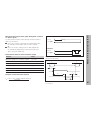
Distance-to-Go Mode
Distance-to-Go Display Mode 1)
Normally, the display shows the actual position of the encoder. However, it is often more helpful to display the remaining distance to an entered nominal position— especially
when you are using the display unit for machine tools and automation purposes. You can then position simply by traversing
to display value zero.
Function of switching outputs A1 and A2
In the distance-to-go mode, switching outputs A1 (pin 15) and
A2 (pin 16) have a different function: they are symmetrical to
the display value zero. For example, if a switching point of
10 mm is entered in P62, output A1 switches at both +10 mm
and –10 mm. The figure below shows output signal A1 when
approaching zero from the negative direction.
You can access the distance-to-go display by entering the
code number 246 582.
Display
Meaning
DELTA ON
Distance-to-go display active
DELTA OFF
Distance-to-go display not active
“Traversing to zero” with distance-to-go display
Path
td1
td2
➤ Select datum point 2.
➤ Enter the nominal position.
➤ Move the axis until the display value is zero.
Time curve of a signal for switching limit (A1) = 10 mm,
td1 ≤ 30 ms, td2 ≤ 180 ms
50
1)
Only in linear measurement mode
Housing
ND 281 B
Benchtop design,
cast-metal housing (W · H · D)
239 mm · 84.6 mm · 224 mm
Operating temperature 0° to 45° C (32° to 113° F)
Storage temperature
–20 °C to 70 °C (–4 °F to 158 °F)
Weight
Approx. 1.5 kg (3.3 lb)
Relative humidity
< 75% annual average
< 90% in rare cases
Power supply
Primary-clocked power supply
100 Vac to 240 Vac (–15% to +10%)
50 Hz to 60 Hz (± 2 Hz)
Line fuse
F 1 A inside the housing
Power consumption
8 W (typically)
Noise immunity
As per VDE 0843 Parts 2 and 4,
severity 4
Protection
IP40 according to IEC 529
Encoder inputs
For linear and angle encoders with
sinusoidal output signals (11 µAPP/1 VPP);
Reference mark evaluation for distancecoded and single reference marks
Input frequency
X1
11 µAPP:
Max. 500 kHz for 60 m cable length
X2
1 VPP:
Max. 100 kHz for 30 m cable length
Display step
Adjustable
Datum points
Two
Functions
•
•
•
•
RS-232-C/V.24
Interface
Baud rates:
110, 150, 300, 600, 1200, 2400,
4800, 9600, 19 200, 38 400 baud
Electromagnetic
1)
Specifications
Specifications
Series of measurements 1)
Sorting and tolerance checking
Switching and sorting signals
Set display and reset display to
zero with external signal
• Measured value output
Only in linear measurement mode.
51
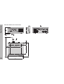
Specifications
ND 281 B: Dimensions in mm/inches
REF 1 2 SET START PRINT inch
< = > MIN ACTL MAX DIFF
172 ± 0.2
6.77" ± .008"
224
8.82"
325
12.8"
33.5
1.37"
140 ± 0.2
5.51" ± .008"
35
1.43"
X
52
239
9.41"
DR. JOHANNES HEIDENHAIN GmbH
Dr.-Johannes-Heidenhain-Straße 5
83301 Traunreut, Germany
{ + 49 / 86 69 / 31-0
| + 49 / 86 69 / 50 61
e-mail: [email protected]
{ Service
+ 49 / 86 69 / 31-12 72
{ TNC-Service + 49 / 86 69 / 31-14 46
| + 49 / 86 69 / 98 99
e-mail: [email protected]
http://www.heidenhain.de
HEIDENHAIN (G.B.) Limited
200 London Road, Burgess Hill
West Sussex RH15 9RD, Great Britain
{ (014 44) 24 77 11
| (014 44) 87 00 24
350 267-21 · SW 349 797-01 · 15 · 1/2001 · E · Printed in Germany · Subject to change without notice
53