1
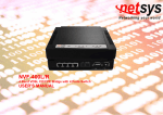
NVF-200LS/Rver.S
4 Band VDSL CO/CPE Modem with Dip Switch
USER’S MANUAL
NVF-200LS/Rver.S 4 Band VDSL CO/CPE Modem USER’S MANUAL Ver. A.3
Copyright
Copyright © 2008 by National Enhance Technology Corp. All rights reserved.
Trademarks
NETSYS is a trademark of National Enhance Technology Corp.
Other brand and product names are registered trademarks or trademarks of their respective holders.
Legal Disclaimer
The information given in this document shall in no event be regarded as a guarantee of conditions or characteristics. With respect to
any examples or hints given herein, any typical values stated herein and/or any information regarding the application of the device,
National Enhance Technology Corp. hereby disclaims any and all warranties and liabilities of any kind, including without limitation
warranties of non-infringement of intellectual property rights of any third party.
Statement of Conditions
In the interest of improving internal design, operational function, and/or reliability, NETSYS reserves the right to make changes to the
products described in this document without notice. NETSYS does not assume any liability that may occur due to the use or
application of the product(s) or circuit layout(s) described herein.
Maximum signal rate derived form IEEE Standard specifications. Actual data throughput will vary. Network conditions and
environmental factors, including volume of network traffic, building materials and construction, and network overhead lower actual
data throughput rate.
1
NVF-200LS/Rver.S 4 Band VDSL CO/CPE Modem USER’S MANUAL Ver. A.3
VDSL Point to Point Solution
The NVF-200LS/Rver.S works as Ethernet to/from VDSL subscriber-site conversion bridge. The NVF-200LS/Rver.S uses
QAM-based 4-band VDSL technology which supports max distance 1.9km (6333 ft.) at 5M/5M or 1.3km (4333 ft.) at 15M/15M, or
800m (2666 ft.) at 25M/25M symmetrical data service. The NVF-200Rver.S also works with NVF-800S/NVF-2400S VDSL IP DSLAM,
together to form a cost-effective solution for services such as remote lecturing, telemedicine, video conferencing, Video-on-Demand
(VOD), IP-TV, Internet access, and various high-speed data applications.
The front-panel provides LED indicators of system and interface status. The built-in POTS/ISDN splitter allows a standard POTS
phone or ISDN device to be connected. Full or half-duplex mode of LAN operations is automatically sensed and configured. VDSL
link rates are configured by local modem or IP DSLAM over auto speed or fix speed function.
Therefore, NVF-200LS/Rver.S supports plug & play operations on the subscriber-site and can do auto and manual selection of the
data speed. An ideal solution for delivering cost-effective, high-performance broadband/multimedia services to Multi-Dwelling Units
(MDU) and Multi-Tenant Units (MTU) such as hotels, campuses and hospitals environments.
2
NVF-200LS/Rver.S 4 Band VDSL CO/CPE Modem USER’S MANUAL Ver. A.3
Safety Warnings
For your own safety, make sure to read and follow all warning notices and instructions before using the device.
• DO NOT open the unit or device. Opening or removing the covers can expose you to dangerous high voltage points or other risks.
ONLY qualified service personnel can service the device. Please contact your vendor for further information.
• Use ONLY the dedicated power supply for your device. Connect the power cord or power adapter to the right supply voltage (e.g.
110V AC in North America or 230V AC in Europe).
• DO NOT use the device if the power supply is damaged as it might cause electrocution. If the power supply is damaged, remove it
from the power outlet. DO NOT attempt to repair the power supply. Contact your local vendor to order a new power supply.
• Place connecting cables carefully so that no one will step on them or stumble over them. DO NOT allow anything to rest on the
power cord and do NOT locate the product where anyone can work on the power cord.
•
•
•
•
•
•
DO NOT install nor use your device during a thunderstorm. There may be a remote risk of electric shock from lightning.
DO NOT expose your device to dampness, dust or corrosive liquids.
DO NOT use this product near water (e.g. in a wet basement or near a swimming pool).
Connect ONLY suitable accessories to the device. Make sure to connect the cables to the correct ports.
DO NOT obstruct the device ventilation slots, as insufficient airflow may harm your device.
DO NOT store things in the device.
• DO NOT use the device outside, and make sure all the connections are indoors. There may be a remote risk of electric shock from
lightning.
•
•
•
•
Be careful when unplugging the power due to transformer may be very hot.
Keep the device and all its parts and accessories out of children’s reach.
Clean the device using a soft and dry cloth rather than liquid or atomizers. Power off the equipment before cleaning it.
This product is recyclable. Dispose of it properly.
3
NVF-200LS/Rver.S 4 Band VDSL CO/CPE Modem USER’S MANUAL Ver. A.3
Table of Contents
Copyright ............................................................................................................................................................................1
VDSL Point to Point Solution............................................................................................................................................2
Safety Warnings .................................................................................................................................................................3
1. Unpacking Information ..................................................................................................................................................6
Check List...........................................................................................................................................................................6
2. Installing the Modem .....................................................................................................................................................7
Hardware Installation.........................................................................................................................................................7
Pre-installation Requirements ..........................................................................................................................................7
General Rules.....................................................................................................................................................................8
Connecting the Modem .....................................................................................................................................................8
Connecting the RJ-11 / RJ-45 Ports..................................................................................................................................9
3. Hardware Description....................................................................................................................................................11
Front Panel .........................................................................................................................................................................11
Front Indicators..................................................................................................................................................................12
Rear Panel ..........................................................................................................................................................................13
Side Panel...........................................................................................................................................................................14
4. Firmware Description ....................................................................................................................................................16
Appendix A: Cable Requirements.....................................................................................................................................17
Appendix B: Product Specification ..................................................................................................................................19
Key Features & Benefits....................................................................................................................................................19
Product Specification ........................................................................................................................................................20
Appendix C: 4 Band VDSL Electrical Characteristics.....................................................................................................22
4
NVF-200LS/Rver.S 4 Band VDSL CO/CPE Modem USER’S MANUAL Ver. A.3
Appendix D: Troubleshooting...........................................................................................................................................23
Diagnosing the Modem’s Indicators.................................................................................................................................23
System Diagnostics...........................................................................................................................................................27
Appendix E: Compliance and Safety Information ...........................................................................................................29
Warranty .............................................................................................................................................................................32
5
NVF-200LS/Rver.S 4 Band VDSL CO/CPE Modem USER’S MANUAL Ver. A.3
1. Unpacking Information
Check List
Carefully unpack the package and check its contents against the checklist.
Package Contents
•
•
VDSL 4-Band Modem (NVF-200LS for CO side / NVF-200Rver.S for CPE side)
AC To DC Power Adapter
•
•
•
•
Four rubber feet
User Manual
RJ-45 cable
RJ-11 cable
Please inform your dealer immediately for any missing or damaged parts.
If possible, retain the carton including the original packing materials.
Use them to repack the unit in case there is a need to return for repair.
6
NVF-200LS/Rver.S 4 Band VDSL CO/CPE Modem USER’S MANUAL Ver. A.3
2. Installing the Modem
Hardware Installation
This chapter describes how to install the modem and establishes network connections and may install the modem on
any level surface (e.g. a table or shelf). However, please take note of the following minimum site requirements before
one begin. Stick the 4 rubber feet at the bottom to avoid scratches.
Pre-installation Requirements
Before you start the actual hardware installation, make sure you can provide the right operating environment, including
power requirements, sufficient physical space, and proximity to other network devices that are to be connected.
Verify the following installation requirements:
•
•
Power requirements: DC 5V/1A or above
The modem should be located in a cool dry place, with at least 10cm/4in of space at the front and back for
ventilation.
•
Place the modem out of direct sunlight, and away from heat source or area with a high amount of
electromagnetic interference.
•
Check if the network cables and connectors needed for installation are available.
7
NVF-200LS/Rver.S 4 Band VDSL CO/CPE Modem USER’S MANUAL Ver. A.3
General Rules
Before making any connections to the modem, please note the following rules:
• Ethernet Port (RJ-45)
All network connections to the modem Ethernet port must be made using Category 5 UTP for 100Mbps,
Category 3, 4 UTP for 10Mbps.
No more than 100 meters of cabling may be use between the MUX or HUB and an end node.
• VDSL Port (RJ-11)
All Home network connections to the RJ-11port must use 24~26 gauge phone wiring.
• We do not recommend using 28 gauge or above phone line.
Connecting the Modem
The modem has one Ethernet port which support connection to Ethernet operation. The devices attached to these
ports must support auto-negotiation or 10Base-T OR 100Base-TX unless they will always operate at half duplex. Use
any of the Ethernet ports to connect to devices such as NIC, Switch, bridge or router.
The RJ-11 line port is used to connect to the RJ-11 modular socket (wall outlet) that is connected to the VDSL 4-Band
CPE modem side (Point to point solution).
The RJ-11 phone port of the modem can be connected to a telephone for making calls
.
8
NVF-200LS/Rver.S 4 Band VDSL CO/CPE Modem USER’S MANUAL Ver. A.3
Connecting the RJ-11 / RJ-45 Ports
1. The modem’s RJ-11 ports supports max distance 1.9km at 5M/5M or max speed 25M/25M symmetrical and
distances up to 800m data service across existing phone wiring, without interfering with standard voice
transmissions, easy-to-use which do not require installation of additional wiring. Every RJ-11 modular phone jack in
the home can become a port on the LAN. Networking devices can be installed on a single telephone wire that can
span within 1.9km or 800m (depends on speed) between the two farthest points. (Figure 1).
Figure 1 VDSL Point-to-Point application
9
NVF-200LS/Rver.S 4 Band VDSL CO/CPE Modem USER’S MANUAL Ver. A.3
2. NVF-200LS/R modem has an embedded splitter between every VDSL side (Line) and POTS (Phone) side. It
permits one to deliver broadband service on the same lines as Plain Old Telephone Service (POTS), PBX, ISDN
traffic and VDSL Signal.
3. The RJ-11 port support max distance 1.9km at 5M/5M or max speed 25M/25M symmetrical and distances up to
800m data service. When inserting a RJ-11 plug, make sure the tab on the plug clicks into position to ensure that it
is properly seated.
4. Do not plug a RJ-11 phone jack connector into the Ethernet port (RJ-45 port). This may damage the modem.
Instead, use only twisted-pair cables with RJ-45 connectors that conform to Ethernet standard.
Notes:
1. Be sure each twisted-pair cable (RJ-45) does not exceed 100 meters (333 feet).
2. RJ-11 port use 24 ~ 26 gauge phone wiring, we do not recommend 28 gauge or above.
3. We advise using Category 3, 4, 5 cables for Cable modem or Router connections to avoid any confusion or
inconvenience in the future when you attached to high bandwidth devices.
4. Be sure phone cable has been installed before NVF-200LS and NVF-200Rver.S power on.
10
NVF-200LS/Rver.S 4 Band VDSL CO/CPE Modem USER’S MANUAL Ver. A.3
3. Hardware Description
This section describes the important parts of the modem. It features the front panel, side panel and rear connectors.
Front Panel
The figure shows the front panel. (Figure 2)
Figure 2 Front Panel
At a quick glance of the front panel, it is easy to tell if the CO modem has power, if it has signal from its Ethernet RJ-45
port and if there is phone line signal on RJ-11 port.
11
NVF-200LS/Rver.S 4 Band VDSL CO/CPE Modem USER’S MANUAL Ver. A.3
Front Indicators
The modem has Five LED indicators. The following Table shows the description. (Table 1)
Table 1 LED Indicators Description and Operation
LED
Color
PWR
(Power LED)
Green
E
(Ethernet LED)
5
(VDSL LED)
15
(VDSL LED)
25
(VDSL LED)
Green
Status
Descriptions
On
The device is receiving the power and functioning properly.
Off
The device is not ready or has malfunctioned.
On
The device has a good Ethernet connection.
Blinking
The device is sending or receiving data.
Off
The LAN is not connected.
On
VDSL is in good linkage at 5Mbps data rate.
Off
The VDSL connection is down.
On
VDSL is in good linkage at 15Mbps data rate.
Off
The VDSL connection is down.
On
VDSL is in good linkage at 25Mbps data rate.
Off
The VDSL connection is down.
Green
Green
Green
12
NVF-200LS/Rver.S 4 Band VDSL CO/CPE Modem USER’S MANUAL Ver. A.3
Rear Panel
The following figure shows the rear connectors. (Figure 3)
Figure 3 Rear connectors
And the table shows the description. (Table 2)
Table 2 Description of the modem rear connectors
Connectors
Type
Description
Line
RJ-11
For connecting to the VDSL modem.
Phone
RJ-11
For connecting to the telephone or Fax, ISDN modem*
Ethernet
RJ-45
For connecting to a Ethernet equipped device
Note: If it is needed to connect to the ISDN modem, please refer to Appendix C for further details.
13
NVF-200LS/Rver.S 4 Band VDSL CO/CPE Modem USER’S MANUAL Ver. A.3
Side Panel
The following figure shows the DIP switch connection. (Figure 4)
Figure 4 Side panel
At quick glance, it is easy to see that the DIP switch pin 1 is switch ON where it is in auto-speed and that is also the
default mode.
Figure 5 DIP switch setting
14
NVF-200LS/Rver.S 4 Band VDSL CO/CPE Modem USER’S MANUAL Ver. A.3
To set the data speed to 25Mbps simply switch ON the pin 2 while the other pins are switch OFF. To change it to
15Mbps, switch ON the pin 3 while the other pins are switch OFF, for 5Mbps switch on the pin 4 while other are switch OFF.
Remember that no two pins can be activated at the same time or it will result in error and for data speed of 5Mbps. Table
shows the summary of DIP switch configuration.
Table 3 DIP Switch Configuration
Speed mode
Pin 1
Pin 2
Pin 3
Pin 4
Auto speed
On
Off
Off
Off
25Mbps
Off
On
Off
Off
15Mbps
Off
Off
On
Off
5Mbps
Off
Off
Off
On
15
NVF-200LS/Rver.S 4 Band VDSL CO/CPE Modem USER’S MANUAL Ver. A.3
4. Firmware Description
Auto and manual data speed selector description:
NVF-200LS/R is a 4band VDSL solution which supports real plug & play and can do auto and manual selection of the
data speed, the setting of the data speed depends on the phone cable length limit, they can support 5M/15M/25M
symmetrical data service but depends on installation environment. If NVF-200LS try to link at 25Mbps data speed but
fails to do so then NVL-200LS data speed must be lower due to the limitation of the phone cable length. If the cable
length is unsure, then auto selection of the data speed at the default setting is recommended. Power must be unplug
before changing of data speed then powered on and wait for VDSL to link again at the correct data speed function.
Speed mode limitation:
5M/5M mode within 1.9km (6333 ft.)
15M/15M mode within 1.3km (4333 ft.)
25M/25M mode within 800m (2666 ft.)
With the above phone cable limit based on without PBX noise.
Note:
We recommend phone cable that must meet Cat 3 standard or above and without clustering, otherwise the above
guarantee will be void.
16
NVF-200LS/Rver.S 4 Band VDSL CO/CPE Modem USER’S MANUAL Ver. A.3
Appendix A: Cable Requirements
A CAT 3, 4 or 5 UTP (Unshielded Twisted Pair) cable is typically used to connect the Ethernet device to the modem. A
10Base-T cable often consists of four pairs of wires, two of which are used for transmission. The connector at the end of
the 10Base-T cable is referred to as RJ-45 connector and it consists of eight pins. The Ethernet standard uses pins 1, 2, 3
and 6 for data transmission purposes. (Table 4)
Table 4 RJ-45 Ethernet Connector Pin out Assignments
PIN
MNEMONIC
FUNCTION
1
TX+
Ethernet differential Transmit signal (+)
2
TX-
Ethernet differential Transmit signal (-)
3
RX+
Ethernet differential receive signal (+)
4
NC
Unused
5
NC
Unused
6
RX-
Ethernet differential receive signal (-)
7
NC
Unused
8
NC
Unused
17
NVF-200LS/Rver.S 4 Band VDSL CO/CPE Modem USER’S MANUAL Ver. A.3
Standard telephone wire of any gauge or flat type, twisted or quad is used to connect the modem to the telephone network. A
telephone cable typically consists of three pairs of wires, one of which is used for transmission. The connector at the end of
the telephone cable is called RJ-11 connector and it consists of six pins. POTS (plain old telephone services) use pins 3 and
4 for voice transmission. A telephone cable is shown below. (Figure 6)
Figure 6 Telephone cable
A
B
The A and B connectors on the rear of the modem are RJ-11 connectors. These connectors are wired identically. The RJ-11
connectors have six positions, two of which are wired. The modem uses the center two pins. The pin out assignment for
these connectors is presented below. (Table 5)
Table 5 RJ-11 Pin out Assignments
Pin#
MNEMONIC
FUNCTION
1
NC
Unused
2
NC
Unused
3
TIP
POTS
4
RING
POTS
5
NC
Unused
6
NC
Unused_
18
NVF-200LS/Rver.S 4 Band VDSL CO/CPE Modem USER’S MANUAL Ver. A.3
Appendix B: Product Specification
Key Features & Benefits
•
•
•
•
Supports Universal Plug & Play
Compliant with IEEE802.3 10BASE-T, IEEE802.3u and 100BASE-TX standard
Compliant with ETSI, ITU & ANSI standards
Max speed at 5M/5M with distance up to 1.9km(6333ft), Max speed at 15M/15M with distance up to 1.3km(4333ft),
Max speed at 25M/25M with distance up to 800m(2666ft)
•
•
•
•
•
•
•
Supports 1 * RJ-11 connector for Ethernet over VDSL
Supports 1 * RJ-11 connector for telephone/PBX connection
Supports 1 * RJ-45 port for 10/100Mbps Ethernet with Auto MDI/MDIX
Supports 1* Dip switch(NVF-200LS only) for speed mode selection
Supports Auto/5/15/25Mbps speed mode and full duplex for VDSL port
Supports long packet size up to 1536 bytes
Supports POTS/ISDN voice pass
•
•
•
•
•
•
•
•
Supports PBO(Power Back Off) function for NVF-200R
Supports 4wires phone set pass through
Voice and Data work on the same telephone line
Spectral compatibility with xDSL, ISDN (2B1Q/4B3T)
Supports flow control IEEE802.3x for Full Duplex & Back Pressure for Half Duplex
Supports Surge protection
Provides Power LED and LED indication Link/Active Status for Ethernet port and Link/Speed for VDSL port
Mini size and metal case for outdoor application
19
NVF-200LS/Rver.S 4 Band VDSL CO/CPE Modem USER’S MANUAL Ver. A.3
Product Specification
Standard:
IEEE802.3 standard
IEEE802.3u standard
Compliant with ETSI, ITU & ANSI standards
Interface:
1 * RJ-45 10/100Mbps Ethernet port
1 * RJ-11 connector for EoVDSL
1 * RJ-11 connector for telephone connection
Cable Connections:
RJ-45 (Ethernet): Category 3, 4, 5 UTP/STP
RJ-11 (EoVDSL): Twisted Pair phone wire
LED indication:
Power
Link/Active Status for Ethernet port
Link/Speed for VDSL port
VDSL Frequency Spectrum:
NVF-200LS Transmitter: 900 kHz ~ 3.9MHz
Receiver: 4MHz & 7.9MHz
NVF-200Rver.S Transmitter: 4MHz ~ 7.9MHz
Receiver: 900 kHz ~ 3.9MHz
POTS/ISDN pass filter Spectrum: 0 ~ 630kHz
20
NVF-200LS/Rver.S 4 Band VDSL CO/CPE Modem USER’S MANUAL Ver. A.3
Power Consumption:
Operating Temperature:
NVF-200LS (LT): 2.15W
NVF-200Rver.S (NT): 2.75W
-20°C ~ 70°C (-4°F ~ 158°F)
Storage Temperature:
-20°C ~ 70°C (-4°F ~158°F)
Humidity:
10% to 90% (non-condensing)
Weight:
0.68kg
Dimensions:
95 x 110 x 24 mm (3.74" x 4.33" x 0.94”)
21
NVF-200LS/Rver.S 4 Band VDSL CO/CPE Modem USER’S MANUAL Ver. A.3
Appendix C: 4 Band VDSL Electrical Characteristics
Parameter
Spectrum
PSD Level
Min.
15Mbps Link Margin
25Mbps Link Margin
Max.
Unit
Transmit
0.9
3.9
MHz
Receive
4
7.9
MHz
Transmit
-70
-61.5
dBm/Hz
Receive
-70
-60
dBm/Hz
Noise Margin
5Mbps Link Margin
Typ.
6
dB
Transmit
27
31
35
dB
Receive
27
31
35
dB
Transmit
36
38
40
dB
Receive
36
38
40
dB
Transmit
41
43
45
dB
Receive
41
43
45
dB
22
NVF-200LS/Rver.S 4 Band VDSL CO/CPE Modem USER’S MANUAL Ver. A.3
Appendix D: Troubleshooting
Diagnosing the Modem’s Indicators
The modem can be easily monitored through its comprehensive panel indicators. These indicators assist the network
manager in identifying problems the hub may encounter. This section describes common problems you may encounter
and possible solutions.
1. Symptom:
POWER indicator does not light up (green) after power on.
Cause:
Defective External power supply
Solution:
Check the power plug by plugging in another that is functioning properly. Check the power cord with
another device. If these measures fail to resolve the problem, have the unit power supply replaced
by a qualified distributor.
Note:
Don’t use other AC to DC power adapter
2. Symptom:
Cause:
Solution:
Link indicator does not light up (green) after making a connection.
Network interface (ex. a network adapter card on the attached device), network cable, or switch port
is defective.
2.1 Power off and re-power on the VDSL modem.
2.2 Verify that the switch and attached device are power on.
2.3 Be sure the cable is plugged into both the switch and corresponding device.
2.4 Verify that the proper cable type is used and its length does not exceed specified limits.
2.5 Check the modem on the attached device and cable connections for possible defects.
23
NVF-200LS/Rver.S 4 Band VDSL CO/CPE Modem USER’S MANUAL Ver. A.3
2.6 Make sure that the phone wire must be connected between NVF-200LS and NVF-200Rver.S
first, when both are to be power on.
2.7 Replace the defective modem or cable if necessary.
3. Symptom:
Cause:
Solution:
VDSL Link cannot be established.
VDSL speed mode setting failure or phone cable length is over the specification limit of the speed
mode.
3.1 Please make sure that the phone wire must be connected between NVF-200LS and
NVF-200Rver.S when both are power on. NVF-200LS will do link speed function depending on
speed mode setting and phone wire length, therefore if NVF-200LS can’t detect
NVF-200Rver.S over phone wire while both power on, this will cause the link to fail.
3.2 Please check phone cable must be 24 gauge with twisted pair and without rust, and the length
is not over 1.9km.
3.3 Please check the correct Dip Switch setting.
Note:
4. Symptom:
Phone cable must meet CAT 3 standard or above and without clustering, otherwise will cause more
cross talk issue to reduce DSL power driver.
VDSL speed mode LED is always flashing
Cause:
VDSL speed mode link is at the limit of phone cable length
Solution:
Note:
Please change speed mode through Dip switch.
Don’t use phone cable that is without twisted pair and under 0.4mm (26 Gauge) diameter.
24
NVF-200LS/Rver.S 4 Band VDSL CO/CPE Modem USER’S MANUAL Ver. A.3
5. Symptom:
Solution:
We tested with a regular S0 bus from an NTBA - data works, but ISDN telephone does not.
You must connect according to the following chart if you want to connect CO and CPE with NTBA.
25
NVF-200LS/Rver.S 4 Band VDSL CO/CPE Modem USER’S MANUAL Ver. A.3
6. Symptom:
Cause:
Solution:
VDSL line is at link margin.
When the VDSL line is linking between 2 speeds at 5/15Mbps or 15/25Mbps.
Fixed the speed to 5Mbps when it is linking between 5/15Mbps or fixed the speed to 15Mbps when it
is linking between 15/25Mbps.
7. Symptom:
VDSL flickers at 25Mbps when multicast streams.
Cause:
Power level is too high and noise immunity is weak.
Solution:
Fixed the speed to 15Mbps, since 15Mbps is ideal for multicast streaming while 25Mbps is for
transferring large data file at high speed.
26
NVF-200LS/Rver.S 4 Band VDSL CO/CPE Modem USER’S MANUAL Ver. A.3
System Diagnostics
Power and Cooling Problems
If the POWER indicator does not turn on when the power cord is plugged in, you may have a problem with the power
outlet, power cord, or internal power supply as explained in the previous section. However, if the unit power is off after
running for a while, check for loose power connections, power losses or surges at the power outlet, and verify that the
fan on back of the unit is unobstructed and running prior to shutdown. If you still cannot isolate the problem, then the
internal power supply may be defective. In this case, please contact your local dealer.
Installation
Verify that all system components have been properly installed. If one or more components appear to be
malfunctioning (e.g. the power cord or network cabling), test them in an alternate environment where you are sure that
all the other components are functioning properly.
Transmission Mode
The default method of selecting the transmission mode for RJ-45 ports is 10/100 Mbps ETHERNET, for RJ-11 port are
5/15/25Mbps VDSL. Therefore, if the Link signal is disrupted (e.g. by unplugging the network cable and plugging it
back in again, or by resetting the power), the port will try to reestablish communications with the attached device via
auto-negotiation. If auto-negotiation fails, then communications are set to half duplex by default. Based on this type of
industry-standard connection policy, if you are using a full-duplex device that does not support auto-negotiation,
communications can be easily lost (i.e. reset to the wrong mode) whenever the attached device is reset or experiences
a power fluctuation. The best way to resolve this problem is to upgrade these devices to a version that support
Ethernet and VDSL.
27
NVF-200LS/Rver.S 4 Band VDSL CO/CPE Modem USER’S MANUAL Ver. A.3
Physical Configuration
If problems occur after altering the network configuration, restore the original connections, and try to track the problem
down by implementing the new changes, one step at a time. Ensure that cable distances and other physical aspects of
the installation do not exceed recommendations.
System Integrity
As a last resort verify the switch integrity with a power-on reset. Turn the power to the switch off and then on several
times. If the problem still persists and you have completed all the preceding diagnoses, then contact your dealer.
28
NVF-200LS/Rver.S 4 Band VDSL CO/CPE Modem USER’S MANUAL Ver. A.3
Appendix E: Compliance and Safety Information
FCC Radio Frequency Interference Statement
This equipment has been tested and found to comply with the limits for a computing device, pursuant to Part 15 of FCC
rules. These limits are designed to provide reasonable protection against harmful interference when the equipment is
operated in a commercial environment. This equipment generates uses and can radiate radio frequency energy and, if not
installed and used in accordance with the instructions, may cause harmful interference to radio communications. However,
there is no guarantee that interference will not occur in a particular installation. If this equipment does cause harmful
interference to radio or television reception, which can be determined by turning the equipment off and on, the user is
encouraged to try to correct the interference by one or more of the following measures:
1.
2.
3.
4.
Reorient or relocate the receiving antenna.
Increase the separation between the equipment and receiver.
The equipment and the receiver should be connected to outlets on separate circuits.
Consult the dealer or an experienced radio/television technician for help.
Changes or modifications not expressly approved by the party responsible for compliance could void the user’s authority to
operate the equipment.
If this telephone equipment causes harm to the telephone network, the telephone company will notify you in advance that
temporary discontinuance of service may be required. But if advance notice isn’t practical, the telephone company will
notify the customer as soon as possible. Also, you will be advised of your right to file a complaint with the FCC if you
believe it is necessary.
29
NVF-200LS/Rver.S 4 Band VDSL CO/CPE Modem USER’S MANUAL Ver. A.3
The telephone company may make changes in its facilities, equipment, operations or procedures that could affect the
proper functioning of your equipment. If they do, you will be notified in advance in order for you to make necessary
modifications to maintain uninterrupted service.
This equipment may not be used on coin service provided by the telephone company. Connection to party lines is subject
to state tariffs.
Important Safety Instructions
Caution: The direct plug-in wall transformer serves as the main disconnect for the product. The socket outlet shall be
installed near the product and be readily accessible.
Use only the power supply included with this product. In the event the power supply is lost or damaged: In the
United States, use only with CSA certified or UL listed Class 2 power supply, rated 5Vdc 1A or above. In
Europe, use only with CE certified power supply, rated 5Vdc 1A or above.
Do not use this equipment near water, for example in a wet basement. Avoid using a telephone during an
electrical storm. There may be a remote risk of electrical shock from lightning.
Do not use the telephone to report a gas leak in the vicinity of the leak.
If trouble is experienced with this unit, please contact customer service at the address and phone listed below. Do
not disassemble this equipment. It does not contain any user serviceable components.
30
NVF-200LS/Rver.S 4 Band VDSL CO/CPE Modem USER’S MANUAL Ver. A.3
FCC Warning
This equipment has been tested and found to comply with the limits for a Class A digital device, pursuant to Part 15 of
the FCC Rules. These limits are designed to provide reasonable protection against harmful interference when the
equipment is operated in a commercial environment. This equipment generates, uses, and can radiate radio frequency
energy and, if not installed and used in accordance with the instruction manual, may cause harmful interference to radio
communications. Operation of this equipment in a residential area is likely to cause harmful interference in which case
the user will be required to correct the interference at his own expense.
CE Mark Warning
This is a CE class A product. In a domestic environment, this product may cause radio interference in which case the
user may be required to take adequate measures.
31
NVF-200LS/Rver.S 4 Band VDSL CO/CPE Modem USER’S MANUAL Ver. A.3
Warranty
The original owner that the product delivered in this package will be free from defects in material and workmanship for one
year parts after purchase.
There will be a minimal charge to replace consumable components, such as fuses, power transformers, and mechanical
cooling devices. The warranty will not apply to any products which have been subjected to any misuse, neglect or
accidental damage, or which contain defects which are in any way attributable to improper installation or to alteration or
repairs made or performed by any person not under control of the original owner.
The above warranty is in lieu of any other warranty, whether express, implied, or statutory, including but not limited to any
warranty of merchantability, fitness for a particular purpose or any warranty arising out of any proposal, specification or
sample. We shall not be liable for incidental or consequential damages. We neither assume nor authorize any person to
assume for it any other liability.
WARNING:
DO NOT TEAR OFF OR REMOVE THE WARRANTY STICKER AS SHOWN, OR THE WARRANTY IS VOID.
32