1
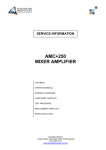
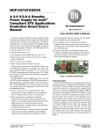
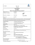
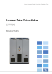
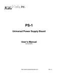
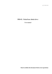
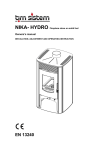
USER MANUAL XLB-2500 Short Arc Xenon Lamp Ballast The XLB-2500 Xenon lamp ballast is a very compact power supply designed for OEM applications. The XLB-2500 is ideal for high power applications where economy is important and performance cannot be compromised. Compact size is possible due to a low-loss Zero Voltage Switching inverter and incorporation of planar magnetics. Power factor is greater than 0.99 and conducted emissions meet stringent European regulations. No additional line filter is required to meet EN 55011 emission requirements. Lumina Power’s XLB series sets the standard for reliable lamp ignition and long term high power operation in a low cost, compact package. The XLB-2500 is ideal for medical, projection and industrial applications where a stable light source is essential. As a Xenon lamp ballast, the XLB-2500 power supply first ignites the lamp with a high voltage pulse and, once the lamp is ignited, acts as a programmable current source delivering constant current based on the input program signal, Iprogram(+), which is normally 0-10V. The XLB-2500 can be configured for output current up to 102A. Maximum output voltage is 35V. Typical lamp voltages are between 20V and 30V. The XLB-2500 utilizes a proprietary low loss, high frequency power factor correction circuit which keeps power factor above 0.98. Power factor corrected power supplies use up to 30% less input current and meet stringent IEC harmonic requirements. The output inverter is a state-of-the-art zero voltage switching (ZVS) inverter which permits very high frequency power conversion with minimum losses and electromagnetic noise. 26 Ward Hill Ave., Bradford, MA 01835 Ph: 978-241-8260 Fx: 978-241-8262 www.luminapower.com Table of Contents Page 3 5 8 10 12 Theory of Operation XLB-2500 Specifications XLB-2500 Interface Installation and Operation Optional RS-232 Protocol Tables and Figures XLB-2500 Block Diagram XLB-2500 Chassis Outline Drawing XLB-2500 Igniter Drawing XLB-2500 Interface XLB-2500 Interface Schematic XLB-2500 Input Connections XLB-2500 Output Connections XLB-2500 Lamp Connections XLB-2500 AC Input Requirements Figure 1 Figure 2 Figure 3 Table 1 Figure 4 Figure 5 Figure 6 Figure 7 Table 2 4 6 5 8 9 10 10 11 12 Symbols used in this document Hazard: This equipment produces high voltages which can be fatal. Only service personnel of Lumina Power, Inc. are qualified to service this equipment High Voltage Present. This power supply produces lethal high voltages. Only service personnel of Lumina Power, Inc., are qualified to service this equipment. Only qualified service personnel are permitted to install this power supply. 2 XLB-2500 Theory of Operation (Refer to Figure 1) The XLB-2500 Xenon lamp ballast has been designed to drive high power Xenon lamps. OEM power supplies for Xenon lamps have the following requirements: Safe lamp operation Reliable short pulse lamp ignition Compact size Power factor correction to conform with CE requirements Low conducted electromagnetic emissions Low leakage for medical applications Referring to the Figure 1, “XLB-2500 XENON LAMP BLOCK DIAGRAM”, the following is a brief description of operation. AC Input Power Circuitry AC input power is processed through a line filter to reduce the conducted EMI to an acceptable level. The XLB-2500 line filter has minimum capacitance to ground to minimize leakage currents. Power Factor Correction Boost Inverter The rectified input power is next applied to power factor boost inverter. This inverter boosts the input voltage to 400VDC. In the process of boosting the input AC voltage, the input AC current is adjusted so that is always in phase with the input AC voltage. Without this power factor correction circuit, the AC input current would be delivered to the power supply in high amplitude, narrow spikes, having a high harmonic content. With power factor correction, the non-50/60 Hz harmonics are reduced to near zero. Since only the fundamental frequency is now used to deliver power, the efficiency of the power supply is improved considerably. One problem with standard input power factor correction circuits is that a high frequency switching circuit is placed across the line in the input side of the traditional input capacitor filter. This circuit results in substantial switching noise conducted to the line. Lumina Power employs a proprietary soft-switching boost inverter which produces minimum switching noise, reduces switching losses, and results in a smaller heat sink associated with the power factor circuit. Zero Voltage Switching (ZVS) Inverter The ZVS inverter and the output transformer are used to step the 400VDC bus down to the appropriate output value. The ZVS inverter is the most modern high frequency/low loss/low noise topology utilized in power electronics today. Instead of running the inverter in a traditional PWM mode, the inverter is run in a phase shift mode. With the appropriate output inductor and the appropriate 3 capacitance across each switching device - in this case MOSFETS - there are 2 virtually no switching losses in the inverter. The only losses in the devices are I R losses associated with the Drain/Source resistance of the MOSFETS. Therefore, the ZVS inverter also contributes to reduced losses, reduce EMI noise and a reduction in overall system heatsink requirements. Output Circuit The output filter is a single stage RC filter designed to keep ripple and output noise very low. Control Circuit The control circuit handles all the responsibilities associated with safe operation of the Xenon lamp. Reliable lamp ignition as well as tight current regulation, overvoltage and over power protection are controlled and monitored in the control circuit. Auxiliary Power All internal power supply requirements as well as the external +15V power supplyand are derived from the power factor control boost inductor. All auxiliary power supplies are regulated by standard linear regulators. Lamp Igniter Module The igniter module provides the 40kV pulse required to break down the Xenon gas and facilitate ignition. In standard configurations, the pulse is applied through the positive output to the lamp anode. Power to the module is provided by the main power supply chassis. Internal circuitry in the igniter module senses the presence of the high voltage arc and briefly disables operation in the main power supply chassis in order to minimize damage from high voltage noise. Figure 1 XLB-2500 BLOCK DIAGRAM 4 XLB-2500-XX-35 SPECIFICATIONS XX = Ioutmax Voutmax= 35V Poutmax = 2500W Model Poutma Ioutmax Input Voltage Size (L x W x H) 200-240VAC 13” x 8.55” x 3.43” 33cm x 21.7cm x 8.71cm x XLB-2500-XX-35 2500W Can be configured to 120A Max Lamp Voltage = 35V Auxiliary Outputs: +15V @0.20A Input Voltage: Power Factor: 200-240VAC, 50/60 Hz, 18.5A@208VAC >.98 Interface (See interface description page 3) Connector: 15 Pin “D” Sub Female Ignition/Boost Boost Voltage: Boost Energy: Ignition Voltage: Igniter Polarity: Ignition Energy: Igniter Dimensions: 250V 500 milli-joulse Up to 45kV (~1uSec rise time) Positive or Negative (Factory Set per customer request) 65milli-joulse. 5.5” x 3.6” x 2.6” 140 x 92 x 66mm Performance Line Regulation: Current Regulation: Current Ripple: Power Limit: <0.2% of maximum output current <0.5% of Maximum output current <0.5% of maximum output current Limited to maximum power with powerfold-back circuit Environment Operating Temp: Storage: Humidity: Cooling: 0 to 40 oC -20 to 85 oC 0 to 90% non-condensing Forced air Regulatory Leakage Current: <350uA Approvals: Medical Safety: Emissions/Immunity: UL60601-1, IEC 60601-1, EN 60601-1, CAN/CSA C22.2 No. 601.1-M90 FCC 47 CFR Class A Emissions, EN55011:1998 Group 1 Class A Emissions, EN61000-3-2 Limits for harmonic current emissions, EN 610000303 Flicker, EN60601-1-2:2001 Electromagnetic emissions and immunity for medical equipment 5 Figure 2 XLB-2500 Chassis Outline Drawing 6 Figure 3 XLB-2500 Igniter 7 XLB-2500-XX-35 Interface Where XX= Ioutmax Voutmax= 35V Poutmax= 2500W Connector Type: 15 pin D-sub Female (Refer to Figure 4 XLB-2500 Interface Schematic) Pin # XLB-2500 Pin Name Lamp On/Off 1 Functional Voltage Level Description High=RUN=+5V to +15V Low = OFF = 0V The Lamp On/Off function is the control function which turns the lamp on and off. When the lamp is turned on, a trigger and boost sequence will ignite the lamp and deliver current as programmed via Iprogram, Pin 7. Open = OFF Connect to GND = RUN The Interlock function can be connected to external interlock switches such as door or overtemp switches. 0 – 10V = 0 – V full scale The output voltage of the supply can be monitored by Vout Monitor. (input) (Note: 1) 2 No connection Do not connect 3 Interlock (input) 4, 9, 15 GND 5 Vout Monitor: (output) 6 Iout Monitor (output) 7 Iprogram(+): (input) 8 Lamp On/Off Status (output) 10,11, 12 No connection Do not connect 13,14 +15V @0.25A (output) 0 – 10V = 0 – Ioutmax 0 – 10V = 0 – Ioutmax Low = Lamp On High = Lamp Off The output current of the supply can be monitored by Iout Monitor. The power supply output current is set by applying a 0-10V analog signal to Iprogram(+). Note that even with Iprogram(+) set between 0V and 2V, when the lamp is turned on via Lamp On/Off, the XLB-2500 will deliver 20% of the maximum current rating of the unit. This is the minimum current required to keep the lamp on. To deliver more than 20% of the maximum rated current, Iprogram(+) must be set higher than 2V. The lamp status is monitored and if at least 20% of the rated current of the power supply is flowing through the lamp, the Lamp On/Off Status signal will be pulled low. When the lamp is off, this pin is pulled high to 15V through a 10K resistor. Auxiliary +15V power supply for user. Up to 0.25A output current available. TABLE 1: XLB-2500 Interface 8 Figure 4 XLB-2500-XX-YY Interface Schematic 9 INSTALLATION AND OPERATION OF XLB-2500 The XLB-2500 chassis is mounted using the mounting brackets as shown in Figure 2, the XLB-2500 Outline Drawing. The XLB-2500 Igniter module has a mounting plate shown in Figure 3. IMPORTANT HIGH VOLTAGE INSTALLATION NOTE The XLB-2500 system trigger module produces a 40kV pulse during lamp ignition. The igniter module should be placed as close as possible to the Xenon lamp in order to keep the leads between the igniter and the Xenon lamp should be kept as short as possible. No other wires should be in the vicinity of the igniter output wires connecting to the Xenon lamp. The HV pulse produces transients that can be destructive to low signal electronics. Please refer to Figure 3, XLB-2500 Igniter Outline Drawing, for information regarding required clearances around the high voltage igniter coil. SAFETY WARNING Because XLB-2500 units are designed for OEM applications, the user must connect AC input power to the power supply chassis. Any input AC voltage must be considered extremely dangerous, and as such, care must be taken to connect AC input power to the unit. AC INPUT 15 PIN INFC Figure 5 XLB-2500 Input Connections OUTPUT TR Figure 6 XLB-2500 Output Connections 1. CONNECTING TO Xenon Lamp Figure 7 shows the interconnections between the XLB-2500, the Igniter module and the Xenon lamp. Because the Igniter module produces a high speed 45kV pulse when igniting the Xenon lamp, it is important to keep connections between the igniter module and the Xenon lamp as short as possible to avoid I2R losses in the wire. The Igniter module is ideally placed as close as possible to the Xenon lamp. 10 Figure 7 XLB-2500 Lamp Connections 11 2. TR Trigger Sense Connection Connect the TR trigger sense connection wire to the trigger module and the XLB-2500 main power supply chassis. The cable for this connection has been provided. The location of the connections is shown in Figure 7. IMPORTANT NOTE Make sure when connecting interface that the current program setting, Iprogram(+), is set no higher then the value required for Xenon lamp operation. When AC power is applied and system is enabled via Lamp On/Off, output current will rise to this program l 3. INTERFACE CONNECTION Connect user system to Interface 15 pin D-sub connector shown in Figure 5. (Although the user interface is typically designed by the user, Lumina Power can provide any assistance necessary to modify interface program and monitor levels) See Table 1 and Figure 4 for description of XLB2500 Interface and the associated simplified interface schematic. 4. INTERFACE INFORMATION BEFORE APPLYING AC POWER: The unit may be programmed for output current via Pin 7, the Iprogram function. But there are three interface control signals which must be properly set before the output will deliver current as programmed by Iprogram. a. INTERLOCK: Pin 3, the Interlock, must be grounded via Pins 4, 9 or 15 in order for the output to deliver current. b. Lamp On/Off: Pin 1, the Lamp On/Off signal is a 5V to 24V signal used to turn the output section on. c. Iprogram: Pin 7. A 0-10V signal results in output current as shown in the table below. Note that even with Iprogram(+) set between 0V and 2V, when the lamp is turned on via Lamp On/Off the XLB-2500 will deliver 20% of the maximum current rating of the unit. This is the minimum current required to keep the lamp on. To deliver more than 20% of the maximum rated current, Iprogram(+) must be set higher than 2V. Iprogram(+) 0V 2V 4V 6V 8V 10V Iout 20% Ioutmax 20% Ioutmax 40% Ioutmax 60% Ioutmax 80% Ioutmax 100% Ioutmax 5. Operating the XLB a. AC INPUT POWER CONNECTION Input power is 200-240VAC, 50/60Hz, 18.5A. Connect AC power connections to power supply input power terminals. Refer to Figure 4 for location of AC Input. 12 Table 2 XLB-2500 AC Input Power Requirements MODEL INPUT POWER XLB-2500-XX-YY 200-240 VAC, 50/60 Hz, 14A @208VAC IMPORTANT SYSTEM NOTE ON AC INPUT POWER Ground wire shall be crimped to a # 8 ring-lug and connected to the ground stud. on both input lines. It does not matter which of the XLB-2500 units are fused two AC inputs are designated Line or Neutral. IMPORTANT APPLICATON NOTE REGARDING AC INPUT POWER AC Input wires and Earth Ground wire should be at least #12 AWG, rated for at least 300V and 105DegC. b. INTERFACE SETTINGS: Make sure INTERLOCK, Pin 3, is connected to GND. c. APPLY INPUT AC POWER Turn ON AC power. After a few seconds the power supply fans will begin to run. d. PROGRAMMING OUTPUT CURRENT Program XLB-2500 power supply for desired output current. A 0-10V signal applied to Iprogram, Pin 7, will program the XLB-2500 for 0 to maximum rated output current. e. Lamp On/Off Apply +5V to +15V to Lamp On/Off, Pin 1. The lamp will ignite. After ignition, XLB-2500 will deliver output current as programmed. 6. Monitoring XLB output and performance: a. Current Monitor Power supply output current can be monitored via pin 6, Iout Monitor. A 0-10V signal will represent the output current from 0 to maximum rated output current. b. Voltage Monitor Power supply output voltage can be monitored via pin 5, Vout Monitor. A 0-10V signal will represent the output voltage from 035V output voltage. c. Lamp On/Off Status Once the lamp has successfully ignited and at least 20% of the maximum rated current of the power supply is being delivered to the lamp, the LAMP ON/OFF Status signal will go low. 13 8. Servicing the XLB-2500 XLB-2500 units have no serviceable parts. Do not attempt to repair or service this unit in the field. For further information, contact Lumina Power at 978-241-8260. Your distributor: 26 Ward Hill Dr., Bradford, MA 01835 Ph: 978-241-8260 Fx: 978-241-8262 www.luminapower.com [email protected] 14