1
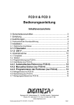
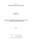
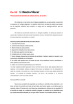
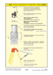
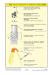
User Manual Flow–Controller Table of Contents 0 1 2 Safety regulations ............................................. 2 Introduction ...................................................... 2 Connections ..................................................... 3 2.1 2.2 2.3 Connection input plug FC-slot A..................................... 4 Connection measuring device ........................................ 5 Connection 230 VAC plug FC-slot B ............................... 6 3 4 Commissioning ................................................. 7 Working mode .................................................. 7 4.1 4.2 Function of the LEDs ...................................................... 7 Reset to zero .................................................................. 8 5 6 7 8 Statistical function ............................................. 8 Programming pulse count/litre without limit ...... 9 Programming pulse count/litre and limit ......... 10 Technical data ................................................ 11 DIGMESA AG KELTENSTRASSE 31 CH 2563 IPSACH Page 1 www.digmesa.com *[email protected] 0 Safety regulations 1. Please read through the Operating Instructions carefully before placing the FC (Flow Controller) into operation. Please perform all steps precisely as instructed. 2. Please follow all the instructions and indications. 3. Always disconnect the electrical power supply before opening the housing. 4. The FC is protected under safety regulation IP44. This means that it is conditionally splashwater-proof; particles may get in the housing 5. Please ensure that the mains voltage used corresponds to the value specified on the name plate. 6. Interrupt the electrical power supply immediately and call a technician in the following cases: Ø Water or other fluids have penetrated the FC. Ø The FC does not function correctly despite precisely following all instructions in these Operating Instructions. On no account may you attempt to modify the unit yourself or remedy the problem by randomly pressing the entry keys. Ø If the FC has been dropped and the housing is damaged. Measurement is not possible without the instrument connected to the electrical power supply! No consumption can be recorded by the FC during an electrical power outage! 1 Introduction The FC has been developed for measuring and monitoring the consumption of fluids. For this purpose, it is connected to the DIGMESA measuring devices fitted in the pipes. The liquid-crystal display informs the consumer of the quantity which has flowed through. The FC with limit value is used, amongst other things, to monitor water filters or water softeners etc. For example: Ø Activated-charcoal filter for cleaning and detoxifying the water. Ø Ion exchanger and filter cartridges for conditioning the water on coffee machines. Ø Monitoring the ion exchangers on washing machines. Ø etc... Page 2 2 Connections The FC is supplied with two different MSDs (magnetic sockets), one with 3 contacts and one with 4 contacts. Plug with 4 contacts ➂ ➃ ➁ ➅ ➀ Plug with 4 contacts ➁ Housing ➂ Fixing screw ➃ Rubber seal, round ➄ Washer ➅ Plastic screw ➆ Rubber seal, rectangular ➇ Plug with 3 contacts ➀ ➄ ➆ Figure 1 Plug with 3 contacts ➂ ➃ ➁ ➅ ➇ ➄ ➆ Figure 2 The underside of the FC accommodates two slots. The MSD with 4 contacts serves as connection between the FC and the measuring device and is conA The MSD with 3 contacts is for the mains connection and is nected to FC FC--slot A. connected to FC FC--slot B B. These MSDs differ and are thus non-confusible. Figure 3 Reset and Interrogation button Page 3 2.1 Connection input plug FC-slot A 1. Remove the MSD with 4 contacts by pushing out the plug ➀ with the fixing screw ➂ on the rear side of the MSD. 2. Remove the plastic screw ➅, washer ➄ and rubber seal ➃. Pull the individual parts in the order in which you removed them over the cable, followed, finally, by the housing ➁. Expose the 3 wires of the cable (3-core, max 0.25 mm2 crosssection) by cutting back the cable sheath over a length of approx. 15 mm. Then strip the insulation from the individual wires over a length of approx. 5 mm. 3. Now screw the three wires into the corresponding terminals: Positive (Digmesa colour code: brown) into terminal 1. Negative (Digmesa colour code: green) into terminal 2. Connect the signal of the flowmeter (Digmesa colour code: white) to the terminal with the earthing symbol. Note down the colours of the cables so that you will be able to then correctly connect the measuring devise (colours of the wires may vary from country to country). Please note that terminal 3 is required only in conjunction with the FC programmer. Plug with 4 contacts ➂ ➁ ➃ ➅ ➀ ➄ ➆ Figure 1 ➀ ➁ ➂ ➃ ➄ ➅ ➆ Plug with 4 contacts Housing Fixing screw Rubber seal, round Washer Plastic screw Rubber seal, rectangular 4. Plug the rubber seal ➆ and plug ➀ onto FC FC--slot A and plug the plug with the earthing symbol onto the earthing symbol FC-slot A. Guide the housing ➁ over the plug ➀ so that the cable outlet is at the right. Now tighten with the fixing screw ➂. 5. Guide rubber seal ➃, washer ➄ and plastic screw ➅ over the cable into the housing ➁ and tighten them so that the cable is held firmly and tightly. Page 4 FC-slot A 2.2 Connection measuring device Confusing the negative and positive cable may destroy the measuring device! 1. You will require an MSD with 3 contacts (Item No. 941-0002/3) in order to connect the measuring device to the FC. This MSD may need to be ordered additionally, depending on the particular measuring device. 2. Connect the MSD to the measuring device as specified in Point 2.1 (Page 4), Point 1 to Point 3. 3. Now plug the rubber seal ➆ and plug with 3 contacts onto the measuring device, earthing symbol plug to (signal symbo measuring device). Guide the housing ➁ over the plug. You yourself can determine in what direction the cable is pointing, dependent on local conditions. Now tighten with the fixing screw ➂. 4. Now guide the rubber seal ➃, washer ➄ and plastic screw ➅ over the cable into the housing ➁ and tighten them so that the cable is held firmly and tightly. Page 5 2.3 1. 2. 3. Connection 230 VAC plug FC-slot B Remove the MSD with 3 contacts by pushing out the plug with the fixing screw ➂ on the rear side of the MSD. Remove the plastic screw ➅, washer ➄ and rubber seal ➃. Pull the individual parts in the order in which you removed them over the cable, followed, finally, by the housing ➁. Expose the 2 wires of the cable (2-core, max 0.75 mm2 crosssection) by cutting back the cable sheath over a length of approx. 15 mm. Then strip the insulation from the individual wires over a length of approx. 5 mm. Now neatly twist the wires, insert them into the individual terminals and firmly tighten them. Insert phase (brown in Switzerland) into terminal 1, negative (blue in Switzerland) into terminal 2. The terminal with the earthing symbol is not used. Plug with 3 contacts ➂ ➃ ➁ ➅ ➇ ➆ ➄ ➁ ➂ ➃ ➄ ➅ ➆ ➇ Housing Fixing screw Rubber seal, round Washer Plastic screw Rubber seal, rectangular Plug with 3 contacts Figure 2 4. Plug the rubber seal ➆ and plug ➇ onto FC FC--slot B B, earthing symbol connector to earthing symbol FC-slot B. Guide the housing ➁ over the plug ➇ so that the cable outlet points to the left. Now firmly tighten with the fixing screw ➂. 5. Guide the round rubber seal ➃, washer ➄ and plastic screw ➅ over the cable into the housing ➁ and tighten them so that the cable is held firmly and tightly. FC-slot B Page 6 3 Commissioning 3.1.1 FC without limit 0.00 and Litres are displayed as soon as the FC is connected to the electrical power supply. 3.1.2 FC with limit The programmed limit value in litres and PROG are displayed for approx. 4 seconds as soon as the FC is connected to the electrical power supply. The FC is then in Working mode, and 0.00 and Litres are shown on the display. 4 Working mode The FC displays the number of litres which have flowed through the flowmeter. This device has an automatic range-selection facility: from 0 to 999.99 litres with two places after the decimal point. If the displayed value exceeds 999.99 litres, the FC changes the display mode and displays only one place after the decimal point up to 9999.9. Above this value, only litres are displayed (up to maximum 99999 litres). After this, it starts again at zero with two places after the decimal point. 4.1 Function of the LEDs 4.1.1 Without limit 1. The green LED lights for as long as the electrical power supply is connected. 4.1.2 With limit The limit value is monitored by the indication of the two LEDs. There are the following four indications: 1. The green LED lights for as long as the electrical power supply is connected. 2. If the number of litres exceeds 90 % of the programmed limit value, the green LED starts to blink. 3. As soon as the limit value is reached, the green LED goes out and the red LED starts to blink. 4. As soon as the limit value exceeds 10%, the red LED lights steadily. Page 7 4.2 Reset to zero Y press the Reset and Interrogation If you wish to set the counter to zero, GENTL GENTLY button on the underside of the housing using the tip of a ball-point pen. Press the Reset button adequately long (approx. 4 seconds) until the display is cleared. The zero-reset function will only have been performed when the display is cleared. As soon as you release the button, value 0.00 and LITRES are shown on the display. 5 Statistical function The device stores the values of the last 24 resets in its internal non-volatile memory. Proceed as follows in order to retrieve this data: 1. Press the Reset and Interrogation button as follows: press for 1 second, release -01 is shown on the display; now for one second, press again, after which St St-01 release and the last value set to zero is shown on the display. 2. If you press Reset a further time, St St-02 -02 is shown on the display. When you release the button, the value prior to the second last zero reset is displayed etc. 3. List all of them until you see End on the display. Then press a further time. If you now release, the FC is once again in Working mode. The litres continue to be counted in the background during the statistics dis dis-play play.. If you do not press the button for 30 seconds, the FC automatically returns to W orking mode. Working Figure 3 Reset and Interrogation button Page 8 6 Programming pulse count/litre without limit The pulse count/litre (calibration factor) can be programmed only with an FC programmer, available as an option, Item No. 925-0200. Proceed as follows in order to change these values: 1. Undo the fixing screw ➂ (Fig. 1) of the MSD slot A to which the cable of the measuring device is connected to the FC and carefully pull the MSD off. The FC remains electrically live. 2. Connect the MSD of the FC programmer to the FC FC--slot A so that the bracket of the MSD points towards the right. The (already set) pulse count per litre is now shown on the display: 4 digits, with the digit at the far right blinking. This pulse count must correspond to that of the connected measuring device. You can find this information on the relevant data sheet or on the Internet at www.digmesa.com. If the pulse value is incorrect, it can be changed as follows. 3. The value of the blinking digit can be change by pressing key digit reaches 9, it changes to 0 by pressing key 4. 5. until the required value is shown on the display. again. This confirms If you have reached the last digit at the left, press key the entries and the display disappears. The display remains blank until the MSD of the FC programmer is unplugged. If you wish to repeat programming, press keys 6. again. in order to access the next digit. Keep on changing the digits with Press key key . When the and simultaneously for 1 sec. When the MSD of the FC programmer is disconnected, 0.00 and LITRES are shown on the FC display. Plug the MSD which you removed in Point 1. onto FC FC--slot A and tighten it with the fixing screw ➂ (Fig. 1). The FC is now once again in Working mode and will count the litres on the basis of the newly set pulse count. Page 9 7 Programming pulse count/litre and limit The limit value (in litres) and pulse count/litre (calibration factor) can be programmed only with an FC programmer which is available as an option, Item No.925-0200. Proceed as follows in order to change these values: 1. Undo the fixing screw ➂ (Fig. 1) of the MSD slot A to which the cable of the measuring device is connected for the FC and pull the MSD carefully off. The FC remains electrically live. 2. Connect the MSD of the FC programmer to the FC FC--slot A A, so that the bracket of the MSD points to the right. The (already set) pulse count per litre is now shown on the display: 4 digits, with the digit at the far right blinking. This pulse count must correspond to that of the connected measuring device. You can find this information on the relevant data sheet or on the Internet at www.digmesa.com. If the pulse value is incorrect, it can be changed as follows. 3. Change the value of the blinking digit by pressing key reaches 9, it changes to 0 by pressing key 4. In order to access the next digit, press key key . When the digit again. . Continue changing the digit with until the required value is shown on the display. 5. When you have reached the last digit at the left, press key again. You will now see a 5-digit number on the display. This number indicates the limit value in litres. 6. Program your required value with the aid of keys Points 3 and 4. 7. When you have reached the last digit at the left, press key again. This confirms the entries and the display disappears. The display remains blank until the MSD of the FC programmer is disconnected. If you wish to repeat programming, press keys 8. and and as described in simultaneously for approx. 1 sec. If the MSD of the FC programmer has been disconnected, 0.00 and LITRES are shown on the FC display. Plug the MSD which you disconnected in Point 1. onto FC FC--slot A and tighten it with the fixing screw ➂ (Fig. 1). The FC is now once again in Working mode and counts the litres on the basis of the newly set pulse count. Page 10 Technical data Mains voltage : 230V~/ ±10 % : 115V~ and 12–24V~ on request : 0.4 W Consumption Measuring functions: Limit measurement Display : from 1 to 65,000 litres : from 0 to 999.99 with counting increment 0.01 litre from 1000.0 to 9,999.9 with counting increment 0.1 litre from 10,000 to 99,999 with counting increment 1litre Pulses/litre : Display : Flowmeter : Statistics memory : Main unit : Temperature range: Power connected : Storage : Power failure 1-9999 Liquid-crystal display All 3-pin Digmesa measuring device the last 24 zero resets 8-bit microprocessor 0oC to +70oC 0oC to +70oC : The values are stored automatically and are not lost. The FC resumes work at the point at which it was interrupted when the electrical power is restored. Measurement is not possible without the instrument connected to the electrical power supply! No consumption can be recorded by the FC during an electrical power outage! 101 *Subject to all technical modifications. 104 58 9.5 2x 92 2.15 25.5 39 Page 11 3.5 14 8 Notes: Your DIGMESA partner T:\Bedienungsanleitung\FC I 823-1007 Page 12 Version:1 März. 2002/ RN