1
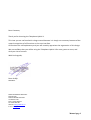
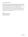
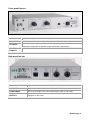
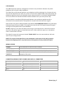
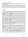
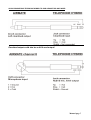
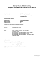
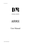
TELEPHONE
HYBRID-1
USER
MANUAL
V.1.02
Dear Customer,
Thank you for choosing the Telephone Hybrid-1.
This time you are not faced with a huge manual because it is simply not necessary because of the
natural recognition of all functions on the user interface.
All functions are self-explanatory and you will certainly appreciate the ergonomics of this design.
We are confident that you will be using the Telephone Hybrid-1 for many years to come, and
wish you a lot of success.
With kind regards,
Duco de Rijk
PRESIDENT
D&R ELECTRONICA WEESP B.V.
Rijnkade 15B
1382 GS WEESP-HOLLAND
The Netherlands
Phone: 0294-418 014
Fax: 0294-416 987
Website: http://www.d-r.nl
E-mail: [email protected]
Manual page 2
What is a Telephone hybrid?
Telephone hybrids provide the interface between professional audio equipment and the public
telephone network. They provide protection for your equipment and the public telephone lines,
allowing for varying line signals and line conditions. Automatically canceling out the unwanted
signal they also facilitate two-way communication down a single telephone line.
Each hybrid has a telephone line connection, a handset connection and separate connectors for
audio input and output from a broadcast mixer, or other professional audio source.
A large proportion of D&R hybrids are used in radio and television broadcasting applications
allowing external callers to be connected to the studio mixing console. Most of the other units
are supplied to communication operations allowing extremely effective conversion between 4wire audio circuits and standard telephone lines.
Specs:
Output: balanced mic level - 30db.
Input: Line level 0 dBu balanced.
R/C balance: fully adjustable
Separation: more than 30db.
Manual page 3
Front panel lay-out
C-BALANCE
12 pole rotary switch to select the optimum side tone attenuation.
R-BALANCE
Internal potentiometer to adjust for optimum side tone attenuation.
TO CALLER
Switch to temporarily connect the line (wall) connector to the Phone
connector (appliance) to be able to dial and make a connection.
ON-LINE
CONNECT
Line connect switch to connect and disconnect calls from the telephone line.
Back panel lay-out
PHONE:
RJ-11 connector to connect with a handset.
LINE (wall)
RJ-11 connector to connect with the public telephone network.
TO MIC INPUT
Stereo jack output to be connected to Mic input of the mixer.
TO CLEANFEED
OPUTPUT
Stereo jack input to be connected to Mix Minus/Clean feed (N1)output of the mixer.
Manual page 4
USER MANUAL
The D&R Telephone Hybrid-1 is designed to create an easy connection between the public
telephone line and your studio equipment.
The Hybrid has to be inserted between your telephone and the telephone line. Connect the two
wires of the telephone line’s wall unit to the RJ-11 connector labeled LINE (wall) and connect the
telephone appliance itself to the Hybrid’s phone output on the RJ-11 connector labeled PHONE.
This can be done with standard available cable assemblies from your local phone shop.
Now the Hybrid is interfaced (fully balanced) between your telephone appliance and its
connection to the outside world. The hybrid can now split the send and return signals.
Now connect the hybrid’s balanced audio input labeled TO CLEANFEED OUTPUT to a (preferable)
balanced output of around +4dBu. This output has to be the mix of all signals except the signal
coming from the hybrid itself to avoid feedback.
An Aux. output on your mixer will do as well as long as you keep the Aux. send of the channel
you return the phone signal on closed (all other Aux. sends need to be open), or in broadcast
mixers a clean-feed is the best.
The Hybrid-1 stereo jack connector labeled TO MIC INPUT has to be connected to a Mic level
input of your mixing console.
NOTE: The output of the Hybrid has to be connected to a Mic input of the mixing console,
because the outgoing level is very low because of the passive circuitry inside the Hybrid.
WIRING SCHEME
PHONE:
RJ-11 connector to connect with a handset.
LINE (wall)
RJ-11 connector to connect with the public telephone network.
TO MIC INPUT
Stereo jack output to be connected to mic input of the mixer.
TO CLEANFEED
OPUTPUT
Stereo jack input to be connected to Mix Minus/Clean feed (N1)output of the mixer.
CONNECTION WIRING OF BOTH PHONE AND LINE RJ-11 CONNECTORS
PHONE/WALL RJ-11
FUNCTION
CONNECTION
Pin 1
n.c.
Pin 2
A (telephone line)
In/out
Pin 3
B (telephone line)
In/out
Pin 4
n.c.
Manual page 5
WIRING OF AUDIO IN AND OUTPUTS
STEREO JACK TO MIC INPUT
/ TOCLEANFEED OUTUT
TYPE
CONNECTION
Screen
Screen (ground)
Audio ground
Tip
Phase (hot)
Audio +
Ring
Non-phase (cold)
Audio -
SPECIFICATIONS
Audio Inputs
TO CLEANFEED OUTPUT
Impedance
10k Ohm, electronically balanced
Common mode rejection
>30dB
Maximum input level
+26dBu
Nominal input level
+4 dBu
Frequency response
20Hz – 15kHz
Connectors
STEREO JACK
TO MIC INPUT
Impedance
< 50 Ohm, electronically balanced
Common mode rejection
>30dB
Maximum output level
-20dBu
Nominal output level
+4 dBu
Bandwidth to telephone line
250Hz – 4kHz, -3dB ref 1 kHz
Telephone line impedance
Nominally 600 ohm
Telephone line impedance
range
300 ohm to 1500 ohm
Connectors
STEREO JACK
GENERAL
Distortion
Less than 0.1% (0dBu out)
Power supply
PASSIVE
Power consomption
NONE
Dimensions
1 HE front panel: 482x44mm
Frame: 240x44x175mm (width x height x depth)
Weight
1.5 kg net including packing
Manual page 6
AUDIO CONNECIONS TELEPHONE HYBRID TO OUR AIRMATE OR ANY MIXER
Cleanfeed output could also be an AUX send output!
Manual page 7
SETTING UP PROCEDURE
Push the "to caller" switch and leave the "connect" switch in the up position. Now dial the caller
to whom you want to talk. If this connection is made you connect the caller to the mixing console
by pushing the connect switch.
Now listen by means of a PFL (CUE) switch on your mixer to the caller and adjust while talking the
C and R balance so that the outgoing signal (your voice) is best attenuated.
A practical start is to put the C balance on number 7 and the R balance on 5. Carefully adjusting
afterwards can be realized by slowly adjusting the R balance for optimum attenuation. This is the
basic setting for most of your calls, because the line balancing to your own telephone station has
to be performed one time only, when no changes are made to the telephone system in your
place. The maximum attenuation will be around 22 to 26 dB.
The function of the "Connect" switch is to connect the hybrid to the telephone line instead of the
phone itself (which is now switched off). The led indicates that a connection has been made.
The function "to caller” is there to disconnect the outgoing signal to the caller for private
discussions
Manual page 8
Declaration of Conformity
volgens ISO/IEC leidraad 22 en EN 45014
Name Manufacturer
Address Manufacturer
D&R Electronica Weesp b.v.
Rijnkade 15B, 1382 GS Weesp,
The Netherlands
declares that the product
Name product
Model nummer
Product options
TELEPHONE HYBRID-1
HYBRID
All
Complies with the following product specifications:
Security
EN 60950: 1988 +A1, A2
EMC:
CISPR-22: 1985 / EN 55022: 1988 klasse B (*)
EN 50082-1: 1992
IEC 801-2:1991 / prEN 55024-2:1992 - 3kV CD, 8kV AD
IEC 801-3:1984 / prEN 55024-3:1991 - 3 V/m
IEC 801-4:1988 / prEN 55024-4:1992 - 0.5kV signal cables,
1 kV power cables.
Additional info:
The product complies herewith to the following rules
Low voltage 73 / 23 / EEG
EMC-rules 89 / 336 / EEG.
(*) The product has been tested in normal users conditions.
Manual page 9
PRODUCT SAFETY
This product is manufactured with the highest standards and is double checked
in our quality control department for reliability in the "HIGH VOLTAGE" section.
CAUTION
Never remove any panels, or open this equipment. No user serviceable parts
inside. Equipment power supply must be grounded at all times.
Only use this product as described, in user manual or brochure.
Do not operate this equipment in high humidity or expose it to water or other
liquids. Check the AC power supply cable to assure secure contact.
Have your equipment checked yearly by a qualified dealer service center.
Hazardous electrical shock can be avoided by carefully following the above
rules.
PLEASE READ THE FOLLOWING INFORMATION
Especially in sound equipment on stage the following information is essential to know.
An electrical shock is caused by voltage and current, actually it is the current that causes the
shock. In practice the higher the voltage the higher the current will be and the higher the
shock. But there is another thing to consider and it is resistance.
When the resistance in Ohms is high between two poles, the current will be low and vice versa.
All three of these; voltage, current. and resistance are important in determining the effect of an
electrical shock.
However, the severity of a shock primarily determined by the amount of current flowing
through a person.
A person can feel a shock because the muscles in a body respond to electrical current and
because the heart is a muscle it can affect, when the current is high enough.
Current can also be fatal when it causes the chest muscles to contract and stop breathing. At
what potential is current dangerous. Well the first feeling of current is a tingle at 0.001 Amp of
current. The current between 0.1 Amp and 0.2 Amp is fatal.
Imagine that your home fuses of 20 Amp can handle 200 times more current than is necessary
to kill. How does resistance affect the shock a person feels.
A typical resistance between one hand to the other in "dry" condition could well over
100,000 Ohm.
If you are playing on stage your body is perspiring extensively and your body resistance is
lowered by more than 50%. This is a situation in which current can easily flow.
Current will flow when there is a difference in ground potential between equipment on stage
and in the P.A. system. Please do check if there is any potential between the housing of the
mikes and the guitar synth amps, which will be linked by your body on stage. Imagine, a guitar
in your hand and your lips close to the mike! A ground potential difference of above 10 volts is
not unusual, in improperly wired buildings it can possibly be as high as 240 volts.
Manual page 10
Although removing the ground wire sometimes cures a system hum, it will create a very
hazardous situation for the performing musician.
Always earth all your equipment by the grounding pin in your mains plug.
Hum loops should be only cured by proper wiring and isolation input/output transformers.
Replace fuses always with the same type and rating after the equipment has been turned off
and unplugged.
If the fuse blows again you have an equipment failure, do not use it again and return it to your
dealer for repair.
And last but not least be careful not to touch a person being shocked as you, yourself could
also be shocked.
Once removed from the shock, have someone send for medical help immediately
Always keep the above mentioned information in mind
when using electrically powered equipment.
Manual page 11
.
TELEPHONE
HYBRID
SERVICE
MANUAL
Manual page 12
Date: 18-08-9918-08-99 [ [16:1716:17]]
BILL OF MATERIAL
D & R Electronica Weesp BV
( SERVICE-MANUAL )
Comp: 100 60898508 Telephone Hybrid-1e 9.5"
---------------------------------------------------------------------------------------------------------Articlecode Description
Quantity Unit
--------------------------------------------------------------------------------------------------------10250345
Bridge rectifier B80C1000
(round)
1.0000 st
10400233
Condensator ker 560p R2.5
1.0000 st
10400234
Condensator ker 680p R2.5
1.0000 st
10400235
Condensator ker 820p R2.5
1.0000 st
10401246
Condensator poly 1n0 R5.0
1.0000 st
10401247
Condensator poly 1n5 R5.0
1.0000 st
10401248
Condensator poly 2n2 R5.0
1.0000 st
10401249
Condensator poly 3n3 R5.0
1.0000 st
10401250
Condensator poly 4n7 R5.0
1.0000 st
10401251
Condensator poly 6n8 R5.0
1.0000 st
10400278
Condensator poly 8n2 R5.0
2.0000 st
10401253
Condensator poly 10n R5.0
1.0000 st
10400273
Condensator poly 12n R5.0
1.0000 st
10401263
Condensator poly 180n R5.0
1.0000 st
10400280
Elco 2.2uF / 50V radiaal R5.0
1.0000 st
10400293
Elco 220uF / 63V radiaal R5.0
2.0000 st
10400281
Elco 4.7uF / 50V radiaal R5.0
1.0000 st
10600432
Jack chassis break
2.0000 st
10600445
Conn Chass 805-D 4p (RJ11)
2.000
st
10300791
Potm 12 1x1KA lin
1.0000 st
10200530
PCB Telephone-hybrid-C
1.0000 st
10550400
Switch Alps 2p-ns (2 x om)
1.0000 st
10550963
Switch Alps 4p-sh (4 x om)
1.0000 st
10550315
Switch rotary 1 x 12
1.0000 st
10950018
Transformer LM-NP-1003-B (PTT line)
2.0000 st
10350517
Resistor 0E 5% 1/4W
1.0000 st
10350718
Resistor 120E 5% 1/4W
1.0000 st
10350792
Resistor 604E 1% 1/4W
2.0000 st
10350728
Resistor 820E 5% 1/4W
1.0000 st
10250351
Zenerdiode 5V6 / 400mW
2.0000 st
10700631
Cap 11.0mm rond zwart
1.0000 st
10700665
cap 14.7mm (12.7x11.3)gat
1.0000 st
10450195
cap SiFam 11mm gray bulk
2.0000 st
10700975
Tape 12mm dun
20.0000 cm
10100371
Front 9.5" Telephonehybrid/E
1.0000 st
10500084
Isolation panel 9.5" randapp.PVC
1.000 st
10600436
Jack Nut
4.0000 st
10700685
Washer M 10 potmeter dun
2.0000 st
10150093
Frame 9.5" 1HE version D
1.0000 st
10450253
Knob Pushbutton 3.3 grey-square
2.0000 st
10450104
Knop SiFam grey D-shaft(11mm)
2.0000 st
10250387
Led 3mm red SLR-03A510-020
1.0000 st
20850531
PCB inserted Telephonehybrid
1.0000 st
Manual page 13
---------------------------------------------------------------------------------------------------------Articlecode Description
Quantity Unit
---------------------------------------------------------------------------------------------------------10700790
Taptite M3x6 verzkop/pozidr/zw
4.0000 st
10800924
Packaging 9.5"
1.0000 st
10800956
Foamblock 9.5"
2.0000 st
Manual page 14