1
100-1
USER MANUAL
UNI EN
ISO 9002
WARNING !
HIGH LEAKAGE CURRENT: first connect to earth !
The rgf100 is a voltage regulator for single-phase motors which operates
connected to the single-phase mains voltage. The regulator must be installed by
qualified personnel who will connect the electric supply, attach the cables in
their permanent positions and commission the plant.
Incorrect installation of the rgf100 voltage regulator or the fan connected to it
may cause damage to objects or people so ensure the instructions in this manual
and all required security measures are read and followed carefully.
• When receiving the goods, check that the packing is intact; in the event of any damage due to
transportation, notify the forwarding agent according to legal requirements.
• The rgf series of products shown in this manual has been manufactured to the highest standards.
• The manufacturer declines all responsibility for accident, loss or damage caused by the use of these
appliances. These must be correctly installed by qualified personnel in conformity with their
destined use and, whenever needed, must undergo correct maintenance which should be carried out
while ensuring the safety of people, domestic animals and goods.
• The purchaser must previously ascertain the suitability of the product for the use it is intended for
and assume all consequent risks and responsibility.
• The rgf100 is a mains voltage regulator which uses the phase-cut principle controll over the sihglephases. It has been designed to vary the effective voltage on single-phase asynchronous motors for
fans following a control signal (either mA, VDC or Ohm). The appliance is manufactured for
industrial use and therefore meets the EMC standards that relate to industrial environments.
• Using the appliance for purposes other than the ones described above will be considered incorrect.
In particular, the appliance may NOT be used to supply machine tools or any other machines
where the motor torque-speed characteristic is not quadratic.
• If the equipment is intended for civil, commercial and/or light industrial use, supplementary
components and other types of equipment are required which can be supplied on specific request
from the purchaser. In this case, the purchaser must provide a suitable design of the plant in which
the appliance is to be installed (compliant with EN 60555 - 2/3 standards regarding disturbance
produced by electrical household appliances and the like.
• We decline all responsibility for any errors in the catalogues, publications or other written
documents. The information in this manual is not binding and we reserve the right to make
changes to the products without prior notice, at any time and in any way that we deem convenient
for production purposes or useful for increasing functionality and performance.
rgf100-1 user manual / V. 2 30.01.02
1
www.selproweb.com
UNI EN
ISO 9002
SAFETY RULES !
This appliance has been designed to give excellent performance provided it is installed and used carefully in
a suitable electric environment by qualified personnel.
The following rules must be obeyed when installing the regulator :
•
•
•
•
•
•
•
•
•
•
•
•
•
•
•
•
•
•
•
Follow the instructions in this manual exactly and observe all safety measures in force.
Do NOT tamper with or disassemble the regulator's internal components; doing so will
INVALIDATE THE GUARANTEE and may cause unnecessary damage.
The regulator does not contain components that can be repaired by the user.
The regulator must be suitably and effectively earthed by the installer according to the standards in force;
earthing is essential for the EMC filter to operate correctly.
The user must be protected from the electric supply and the motor must be protected from possible
overloads in compliance with the standards in force.
DO NOT supply the regulator without the internal protection panel made from lexan.
DO NOT touch the electrical parts of the circuit when the power supply is connected under any
circumstances.
Before supplying power to the unit, check carefully that the power and earth are correctly connected.
If the mains supply is "disturbed", which may be due to other electrical power components causing
irregularities in the supply (power contactors), it is recommended that supplementary single-phase
‘ SURGE ARRESTER’ filters are installed directly on the regulator supply.
Avoid repeatedly connecting and disconnecting the power supply to the regulator; a constant supply
keeps the regulator at working temperature and eliminates problems caused by condensate inside the
protection case.
Install the regulator out of direct sunlight so that the container cannot get overheated and cause a
reduction in the maximum load current.
The appliance may operate at environmental temperatures up to 50° C. Do not install it where this
temperature may be exceeded or the integrity of the regulator will be compromised and the appliance
may make the user appliance operate at full load (100%) with all consequent effects.
The appliance must be stood vertically to encourage heat dissipation and to ensure there is a sufficient air
circulation and free space measuring 150 mm above and below the regulator. If several regulators are to
be grouped together on a single electric board, provide forced air circulation with a fan or cooling unit of
sufficient power.
Use the holes on the lower and power terminal board sides of the appliance, for entrance of the
connection cables. This will prevent water, dust etc. from getting in and will ensure the IP55 protection
level is maintained using adequately sized cables and sheaths of suitable quality.
Reassemble and check the cover of the external protection panel is properly closed.
DO NOT alter or damage the identification stickers on the equipment.
DO NOT force the trimmers to rotate beyond their set mechanical travel.
Only alter the trimmers intended for regulation.
Under no circumstances alter the trimmers marked with the spot of red paint.
WARNING !
HIGH LEAKAGE CURRENT: first connect to earth !
rgf100-1 user manual / V. 2 30.01.02
2
www.selproweb.com
UNI EN
ISO 9002
CONTENTS
1.0
2.0
3.0
4.0
5.0
6.0
PRESENTATION … … … … … … … … … … … … … … … … … … … … ..… .… … … … … … … … … … …
1.1
DESCRIPTION … … … … … … … … … … … … … … … … … … … … … … … … … … … … … … ..
1.2
INSTALLATION AND MECHANICAL DIMENSIONS … … … … … … … … … … … … … … … … … ..
1.3
PRINCIPLE OF OPERATION … … … … … … … … … … … … … … … … … … … … … … … … … …
1.3.1 OPERATING MODE … … … … … … … … … … … … … … … … … … … … … … … … …
1.3.2 APPLICATIONS … … … … … … … … … … … … … … … … … … … … … … … … … … … .
1.4
ELECTRIC MOTORS … … … … … … … … … … … … … … … … … … … … … … … … … … … … ..
1.4.1 MAGNETOTHERMAL PROTECTION … … ..… … … … … … … … … … … … … … … … …
1.5
RGF 100-1 TECHNICAL DATA … … … ..… … … … … … … … … … … … … … … … … … … … … .
ELECTRICAL CONNECTIONS … … … … … … … … … … … … … … … … … … … … … … … … … … … …
2.1
POWER CARD : ELECTRICAL CONNECTIONS … … ..… … … … … … … … … … … … … … … … … .
2.2
ANALOGUE INPUT SIGNALS : ELECTRICAL CONNECTIONS … ..… ...… … … … … … … … … … ..
2.2.1 CONNECTION OF XSK PRESSURE TRANSDUCER (4-20 mA) … … … … … … … … … …
2.2.2 CONNECTION OF NTC TEMPERATURE SENSOR (10 KOHM @ 25° C) … … … … … … ..
2.2.3 CONNECTION OF OTHER SENSORS AND CONTROL SIGNALS … .… … … … … … … … … .
2.2.4 REMOTE CONNECTION FOR A CURRENT (mA) OR VOLTAGE (VDC) CONTROL SIGNAL .
2.2.5 CONNECTION OF THE RGF MULTITRANSDUCERS CONTROL … ..… … … … … … …
4
7
8
9
10
10
11
11
12
13
13
14
15
17
18
19
20
COMMISSIONING PROCEDURE … … … … … .… … … … … … … … … … … … … … … … … … … … … …
3.1
JUMPERS … … … … … … … … … … … … … … … … … … … … … … … … … … … … … .… … … ..
3.2
MASTER, VERSION B (4-20 mA) … … … … … … … … … … … … … … … … … … … … … … … …
3.3
MASTER, VERSION G (0-10VDC) … … … … … … … … … … … … … ..… … … … … … .… … … …
3.4
SLAVE, VERSION E (0-20mA) … … … … … … … … … … … … … … … … … … … ..… ..… … ..… .
3.5
SLAVE, VERSION F (0-10VDC) … … … … … … … … … … … … … ..… … … … … … ..… … … … ..
3.6
MASTER, VERSION D, C OR L (NTC ° C) … … … … … … … … … … … … ..… … … … .… … … ..
3.7
OPTIONAL MODULE FOR CENTESIMAL SET-POINT … .… … … … … … … … … … ..… … … .… ...
CONTROL TRIMMER … … … … … … … … … … … … … … … … … … … … … … … … … … … … … … …
4.1
OPERATING MODE SELECTION … … … … … … … … … … … … … … ..… … … … … … … … … …
4.2
CALIBRATION TRIMMER … … … … … … … … … … … … … … … … … … … … … … … … … … ..
4.3
MAX. OUTPUT REGULATION … … … … … … … .. TRIMMER P4 … … … … … … … … … … …
4.4
MIN OUTPUT REGULATION … … .… … ..… … ..… . TRIMMER P5 … … … … … … … … … … …
4.5
PROPORTIONAL BAND REGULATION … … ..… … ... TRIMMER P2 … … … … … … … … … … …
4.5.1
VERSIONS WITH MASTER REGULATOR OPERATION … … … … … … … … … … … … ..
4.5.2
VERSIONS WITH SLAVE REGULATOR OPERATION … … … … … … … … … … … … … .
4.6
SET-POINT REGULATION … … … … … … … … … … TRIMMER P3 … … … … … … … … … … ..
4.7
SOFT-START REGULATION … … … … … … ...… … . TRIMMER P1 … .… … … … … … … … … .
21
21
22
22
23
23
24
25
26
26
26
27
27
28
28
29
30
31
… … … … … … … … … … … … … … … … … ..
TROUBLESHOOTING INSTRUCTIONS . . . … … ..… … … … … … … … … … … … … … … … … … … … .
32
33
RGF 100-1 EASY REFERENCE COMMISSIONING GUIDE
rgf100-1 user manual / V. 2 30.01.02
3
www.selproweb.com
UNI EN
ISO 9002
1.0 PRESENTATION
THANK YOU for choosing an rgf100-1 series single phase voltage regulator designed specifically to give the
maximum yield and greatest ease of use.
Like all our products, it has been built to the very highest quality standards using electronic components of
the utmost reliability which have undergone functional tests that guarantee use of the product for at least
30,000 hours of continuous operation without problem.
The rgf100-1 regulator is a power unit designed to meet requirements of quality and flexibility of use in
plants and machines in which proportional variation of the speed of rotation of the fans is essential.
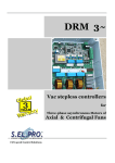
The regulator is housed in a GEWISS GW Plast 120°C case (fig. 1) which guarantees high heat resistance
during ordinary use (120°C), increased mechanical impact resistance (IK = 08) and a protection level (IP55)
that allows the regulator to be installed out of doors.
The rgf100-1 control is shown in fig.1.
Vdc - mA - NTC
fig. 1
Before installing the rgf100-1, you are invited to read this manual which describes the necessary
procedures for correct installation and commissioning of the machine.
rgf100-1 user manual / V. 2 30.01.02
4
www.selproweb.com
UNI EN
ISO 9002
Like all our products, the rgf100-1 series bears CE marking as required by directive 89/336/ECC and its
subsequent modification EEC/92/31 on electromagnetic compatibility.
Since all these products are not used as "stand alone" appliances but incorporated into other plants or
machines, the standards' compatibility test was carried out under typical operating conditions.
The essential requirements of the directive are satisfied by conformity to "generic standards" for heavy
industry.
EN 50081-2 emission standard, EN 50082-2 immunity standard, and in particular:
EN 55011
EN 55011
ENV 50140 (IEC 801-3)
ENV 50141
IEC 801-4
IEC 801-2
class B, for radiated disturbances
class A, for conducted disturbances
for susceptibility (on the power supply)
for conducted susceptibility on power lines
for fast transistors (bursts / high frequency disturbances)
for electrostatic discharge (ESD)
The tests and checks for conformity have been carried out according to the procedures described in the
product's technical documentation. The system used was formed by an rgf100-1 voltage regulator, a control
cable and relative controls, a power supply cable, a motor cable and a fan.
Responsibility for the final characteristics of the system or plant regarding the EMC directive
rests with the installer. The equipment must be installed in observance of the regulations in
force using the information presented in this manual.
3
IP 55
120° C
STOCK & WORK
- 20
° C +85
- 10
° C +50
UR%
fig. 2
rgf100-1 user manual / V. 2 30.01.02
5
www.selproweb.com
UNI EN
ISO 9002
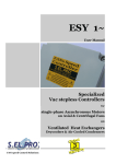
Fig. 3 represent the rgf100-1 regulator with the general contents
13
Soft
start
Proportional
Band
M
m
Max.
Output
M
M
C
Set
Point
M
C
m
Min.
output
M
C
C
m
m
C
12
m
11
10
EN 61000-4-5
9
8
7
1
2
3
4
5
6
fig. 3
CONTENTS of rgf100-1 regulator
1.
3.
5.
7.
9.
11.
13.
Terminal block for single-phase power supply (F - N)
Terminal block for PE connection
Terminal block for analog input signal
Cover screws
Power card (lower)
GEWISS GW Plast 120° C case
Control Trimmer for work parameters regulation
rgf100-1 user manual / V. 2 30.01.02
2.
4.
6.
8.
10.
12.
6
Terminal block for load connection (M1 – M2)
SURGE ARRESTER circuit / PE faston connection
Screws hole for wall installation
Black anodized heat sink
SURGE ARRESTER circuit like EN 61000-4-5
Control card (upper)
www.selproweb.com
UNI EN
ISO 9002
1.1
DESCRIPTION
The rgf100-1 series single-phase cutting regulators comprises one electronic cards on a vetronite support
mounted inside the GEWISS IP55 GW Plast 120°C case.
The cards represent the control section (upper) and power section (lower).
Soft
start
Proportional
Band
M
m
P2
Min.
output
M
C
m
P1
Max.
Output
m
M
C
Set
Point
C
M
P3
M
M
C
m
P4
Factory
calibration
C
m
m
P5
P0
1 2
1 2
1 2
+10
Vdc
M1M2 N F
+24
Vdc
PE
1
2
3
IN GND +V
fig. 4
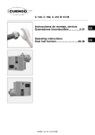
The control card contains the following regulation, connection and signalling components:
•
•
•
•
trimmers
jumpers
Inputs signals
terminal block
power supply
terminal block
Marked "Pn"; used to set working parameters
Marked 'Jn'; used to change preset operational modes
Terminal board (IN – GND - +V) for connection of the control analogue input
signal
'F-N' for VAC input supply
'M1-M2' for output supply to load
‘PE' for the Earth / PE connection
rgf100-1 user manual / V. 2 30.01.02
7
www.selproweb.com
UNI EN
ISO 9002
1.2
INSTALLATION AND MECHANICAL DIMENSIONS
The rgf100-1 regulator must always be securely assembled and fixed using the four (4) attachment screws on
the side fins before connecting to the power supply.
The holes provided on the lower part of the regulator are for entry of the electric connection cables:
• three pole line (F + N + Earth) to power the regulator,
• three pole line (M1 + M2 + Earth) to power the load,
• signal cable lines for the analogue inputs and digital outputs.
To make installation simpler, all regulators are also fitted with stuffing boxes in PA6 polyamide, class V2,
IP68, for use with the power and signal cables.
The regulator is cooled by natural convection and so air must be able to pass freely below and above the
appliance.
Therefore ensure there is at least 150 mm of free space above and below the regulator.
Montaggio verticale : corretto
Wall mounting : correct
Montage vertical : correct
Wandmontage : Richtig
150 mm
FA
D
150 mm
6
fig. 5
Mechanical Dimensions
MODELS
A
B
C
D
E
F
Kg.
∅ Fixing
screw holes
rgf 110
rgf 116
240
152
115
195
108
210
1,6
1,7
∅6
Table 1
rgf100-1 user manual / V. 2 30.01.02
8
www.selproweb.com
UNI EN
ISO 9002
1.3
PRINCIPLE OF OPERATION
The rgf100-1 series appliances are voltage regulators that use the phase cutting principle.
The regulators, also referred to as speed controls, have been designed to change the average voltage on the
following types of equipment, according to a control signal:
• asynchronous single phase motors connected to fans, pumps, agitators, mixers;
• electrical resistor devices.
Regulation occurs as a result of cutting of the input sinusoid. Regulation does not generate any torque knock
or pulsation and is particularly quiet. Any voltage loss is contained within a maximum limit of 1%.
Fig. 6 shows a block diagram of regulator rgf100-1.
POWER
CARD
CONTROL
SIGNAL
CARD
E
F
F
N
C
AB
D
PE
M2
M1
A - Power circuit
B - Mains filter and EMC
protective devices
C - Power supply and synchronism
signals
D - Insulators for the control
signals of the power devices
E - Regulation and control circuit
F – Modulator for control of the
power devices
fig. 6
The speed regulators are sized to withstand a starting current equal to more than twice the rated current;
therefore, when choosing a regulator, it is essential to take into consideration both the motor starting current
and the type of motor.
It is actually well-known that, while the starting current in axial fans is equal to 2 or 3 times the rated current,
the same current in centrifugal fans can have values around 7 or 8 times the rated current.
As far as the choice of motor is concerned, it is advisable to choose motors suited to the type of regulation.
As a general rule, the best suited are:
• motors with high slipping resistive motors
• defluxed motors
• tropicalized motors
• CLASS H motors
as these allow better performance to be obtained with speed changes, they are quieter and start with lower
current.
When choosing a motor, it is always advisable to contact your own supplier and order a motor which is
suitable for speed control by voltage change. Subsequently, practical trials should be carried out on the
motors or prototype machines in order to check their correct operation.
After choosing the motor, the speed regulator must be ordered according to
• the rated voltage,
• maximum power required (load-Amperes) bearing in mind the starting current.
rgf100-1 user manual / V. 2 30.01.02
9
www.selproweb.com
UNI EN
ISO 9002
After the motor characteristics have been checked, the following should be defined in order to identify the
type of operating mode and application.
1.3.1 Operating mode
The rgf controls allow two different types of operation depending on which type of input is available:
•
operation as REGULATOR (also called MASTER)
the phase cutting regulators is directly connected to one or more sensors; the phase cutting is a function of
the values selected for:
q Set-point (SP trimmer P3)
q Proportional band (PB trimmer P2)
•
operation as POWER UNIT (also called SLAVE)
In this case, the rgf is set up to be controlled by an external Master regulator which decides the phase cutting
of the voltage by sending the control signal to the slave.
The incoming control signal to the rgf100-1 regulators can be:
For a MASTER (mA – Vdc)
For a MASTER (ohm)
For a SLAVE (mA – Vdc)
Active sensors with control in current (mA) or voltage (Vdc)
NTC sensors with control in °C/ohm ( 10kohm @ 25 °C )
Control signals in current (mA) or voltage (Vdc)
1.3.2 Applications
It is generally possible to connect one sensors / control signals to the ‘MASTER’ and ‘SLAVE’ models.
In the case of active sensors, this can be directly powered (24Vdc / max. 40 mA).
The principal applications are for measuring pressure (bar), temperature (°C), humidity (%RH), delivery
(cu.m/h), superpressure (mm.), static pressure (Pa), supertemperature (destratification) etc. in plants and
machines.
PB
max.
max.
min.
(min.)
(cut-off)
0
SP
MASTER
100%
SLAVE
fig. 7
rgf100-1 user manual / V. 2 30.01.02
10
www.selproweb.com
UNI EN
ISO 9002
1.4
ELECTRIC MOTORS
Single phase asynchronous motors can be connected to the rgf100-1 regulator in applications where the
torque-motor speed characteristic is quadratic.
This mainly allows phase cutting application with axial and centrifugal fans used for control purposes.
The correct electrical connection and the supply voltage are given on the motor's specifications plate.
It is important to keep the motor power supply cable as short as possible to reduce the level of interference
and leakage currents to a minimum (10 / 15 mt); if the cable has to be long, an auxiliary filter of exactly the
same power as the regulator must be installed on the regulator output.
The figure below shows the connection configurations.
M1
U1
2 WIRE
CONNECTION
Clockwise
rotation
Z1
M2
Z2
M1
U2
U1
Anti-clockwise
M2
rotation
Z2
Z1
Z1
Z2
Z2
Z1
U1
U2
U1
U2
U2
3 WIRE
CONNECTION
M2
Clockwise
rotation
M2
Anti-clockwise
rotation
F
M1
F
M1
Z1
Z2
Z2
Z1
U1
U2
U1
U2
fig. 8
The rgf100-1 regulator can control several motors connected in parallel but the absorption of the motors'
total current must never exceed the rated current as given on the rgf100-1's specification plate.
The speeds of the motors vary at the same time though any differences in behaviour during start up and at
low speeds are due to slight differences between the motors even if they are of the same type. However, if
the required speeds of the motors are different, motors must be used with different rated speeds. Bear in
mind though that motors with very different characteristics create different electrical situations and these
may cause problems on start up and at low speeds caused by different resistances of the stators which require
different voltages on start up and at low speeds.
1.4.1 Magnetothermal protection
rgf100-1 devices must be protected by a magnetothermal switch fitted upstream of the cutting regulators.
Installation of magnetothermal protections is the responsibility of the installer.
It is advisable to fit an automatic magnetothermal protection with a 'C' intervention curve having the
following capacity:
rgf models
magnetothermal
carrying capacity
rgf 110
rgf 116
16 A
25 A
Table 2
rgf100-1 user manual / V. 2 30.01.02
11
www.selproweb.com
UNI EN
ISO 9002
1.5
rgf 100-1 TECHNICAL DATA
SUPPLY
CURRENT
POWER
OPERATING
PRINCIPLE
OPERATING
CHARACTERISTIC
INPUT SIGNALS
OUTPUT SIGNAL
ADJUSTMENTS
AND
PRESETTINGS
PROTECTIONS
CASE
INSULATION
TEMPERATURE
HUMIDITY
INSTALLATION
ELECTRICAL
CONNECTIONS
TECHNICAL
STANDARDS
Voltage
Frequency
Overvoltage protection
Rated
Overload
Control circuits
Dissipated in
environment
230VAC +/- 10 % Single-phase
50 Hz ( 60 Hz on request)
for installation Category II ( 4 KV )
10 A up to 50°C environment , over decrease by 0.5 A/°C
RGF 110
16 A up to 50°C environment , over decrease by 0.8 A/°C
RGF 116
200 % of the rated current (max. 10”every 3’)
3VA
RGF 110
20 W @ 10A
RGF 116
32 W @ 16A
Cutting phase with compensation for inductive loads and motors
POWER Unit
The output voltage depends on the control signal applied to the input,
(Vers.E , F )
according to the specific appliance regulating curve
Regulator
The output voltage changes to keep the quantity measured by the transducer
(Vers.B , C , D , G , L ) set to the target point, chosen by means of the Set-Point.
Vers. E
One 0-20 mA , Ri = 100 Ohm analog input
Vers. B
One 4-20 mA , Ri = 100 Ohm analog input
Control
Vers. F,G
One 0-10 Vdc analog input with Ri = 10 Kohm input impedance
Vers. C,D,L One analog input specific for the NTC sensor supplied (10K@25°C)
Versions B, G, E
+20V -10/+20%, 40 mA non-stabilized rated voltage
Version F
+10V/5mA stabilised voltage
Version & Input
B: 4-20 mA
G: 0-10 V C:-10/+40°C D:+20/+70°C L:-30/+20°C
Target value
4...20 mA
0..10 V
-10..+40 ° C
+20..+70 ° C -30 +20 ° C
Proportional range
0.7..7.0 mA
1..6 V
2… 30 ° C
Minimum Limit
Adjustable from 0% to 100%
Maximum Limit
Adjustable from 100% to 0%
Acceleration ramp
Adjustable 1”to 10”
EMC integrated mains According to EN 55011 (CEI 110-6) Class B : ISM appliances directly
filter
connected to low voltage power mains
Overvoltage protection According to EN 61000-4-5 : overvoltage Category II (4 KV)
Dimensions and Weight 240 x 150 x 115 mm
1.6 kg / 1.7 kg.
Materials
GW-Plast 120°C and black anodised aluminium
Degree of protection
IP 55
Environmental pollution Strong pollution
Fire resistance
Category D
Case
Class I (use of earthed protection cable)
Control circuits
4000V between control input and mains voltage components
Working
-10 T 50 ( from -10° C to + 50° C )
Storing
-20 T 85 ( from -20° C to + 85° C )
RH < 85%
Vertical wall-mounting only, with No 4 ∅ 6 mm. holes
Signal
Trailing cable with rated cross section max. 1.5 sq mm / 22-14 AWG Cu
Power
Trailing cable with rated cross section min. 2.5 sq mm / 20-12 AWG Cu
89/392/EEC Directive
CEI-EN 60204-1 : “Safety of machinery”
73/23/EEC Directive
EN 50081-2 Generic standard for industrial environment emission
EN 50082-2 Generic standard for industrial environment immunity
EN 55011 class B, for radiated disturbance
EN 55011 class B, for conducted disturbance
89/336/EEC Directive
ENV 50140 (IEC 801-3) for susceptibility (on the supply)
ENV 50141 for conducted susceptibility on the signal lines
IEC 801-4 for fast transients (burst / high-frequency disturbance)
IEC 801-2 for electrostatic discharge (ESD)
Table 3
rgf100-1 user manual / V. 2 30.01.02
12
www.selproweb.com
UNI EN
ISO 9002
2.0 ELECTRICAL CONNECTIONS
2.1
POWER CARD : ELECTRICAL CONNECTIONS
For supply and load connection, reference should be made to the diagrams shown in fig. 9, making sure the
section of the cables is adequate to the connected load.
The power cables (supply and load) must be installed separately from the control cables (analogue input)
keeping the maximum distance possible between the conductors.
Do not place power cables with signal cables in the same raceway. If the cables cross one another,
ensure it is at 90°.
ATTENTION : connect the earth conductor to the screw placed purposely beside the dissipator. Use
heat resistant cables able to withstand temperatures greater than 90°C.
SURGE ARRESTER : electric protection placed between the regulator supply and the earth to protect
the device from transitory mains excess voltage.
ATTENTION : disconnect the faston contact from the earth reference in the 'electric strength test’.
The rgf100-1 regulators allows connection of single-phase load.
It is advisable to provide a by-pass switch to allow load activation even when the cutting regulators is faulty
(emergency by-pass).
When connecting the by-pass, the following precautions should be taken into consideration:
i) connection made through the by-pass switch must keep phase correspondence unaltered so as to
avoid destructive shortcircuits and maintain the motor's sense of rotation.
ii) before supplying the load with maximum voltage, supply to the regulator should be disconnected,
therefore:
• it is advisable to use a three-position manual switch as a commutation device
• if automatic commutation is carried out by means of contactors, make sure there is some delay (at
least 2 seconds) between regulator disconnection and load activation operations.
Electrical connection of the supply and load for 10A & 16A rgf100-1 regulators is shown in fig. 9
Disconnect PE faston before dielectric strenght test
By
Pass
fig. 9
rgf100-1 user manual / V. 2 30.01.02
13
www.selproweb.com
UNI EN
ISO 9002
2.2
ANALOGUE INPUT SIGNALS : ELECTRICAL CONNECTIONS
The connections for the control analogue inputs are described below.
They can be connected to the analogue input terminal board, in particular:
MASTER version
MASTER version
SLAVE version
CONNECTIONS
Active sensors with control in current (mA) or voltage (Vdc)
NTC sensors with control in °C (per 10kohm = 25 °C)
Control signals in current (mA) or voltage (Vdc)
Trailing cable with rated cross section min. 1.5 sq mm / 22-14 AWG Cu
XSK
4-20mA
NTC
10kohm
@ 25° C
4 IN
0-20mA
0-10Vdc
mode
4 INPUT
AUXILIARY
mA / Vdc
NTC
RGF-MEI
0-10Vdc
mode
s et
s et
on off
on off
CFI
CFI
fig. 10
rgf100-1 user manual / V. 2 30.01.02
14
www.selproweb.com
UNI EN
ISO 9002
One of the main applications of the rgf100-1 series regulators is the control of voltage and speed of rotation
of fans.
This is modulated to keep temperature or pressure constant as a work point for one or more refrigerating
circuits (condensator or evaporator mode).
In the STANDARD condition, the fan reaches maximum output voltage (or P4) coinciding with the work
Set-point.
Directions are given below for connection or calibration of rgf100-1 regulators with active pressure
sensors, NTC temperature sensors and other possible applications for direct or remote regulation.
2.2.1 Connection of XSK pressure transducer 4-20 mA
The fig. 11 show the rgf100-1 with Trimmer and centesimal switch for Set-Point P3
Soft Proportional Set
Start
Band
Point
M
M
C
m
M
C
m
P1
Min.
output
M
M
C
P3
1
2
P4
Factory
calibration
Soft Proportional
Start
Band
M
C
m
m
P2
Max.
Output
M
C
m
C
m
P5
m
P0
m
M
C
m
P1
J1
Min.
output
M
M
C
M
m
M
C
m
P4
2
Factory
calibration
C
P2
1
J2
Max.
Output
m
P5
P0
J1
J2
9 0 1
8
7
9 0 1
2
3
6 5 4
SW1
8
7
2
3
6 5 4
P3
SW2
SET-POINT
M1M2 N F
PE
M1M2 N F
1 2 3
PE
1 2 3
fig. 11
Fig. 12 shows the connection of pressure transducer plus the type of operation (standard) and the operating
regulation controls
PRESSURE TRANSDUCER
ACCURACY
4-20mA
0-10Vdc
+/- 3% FS
+V
GND
IN
3
2
1
XSK
fig. 12
WARNING : do not invert the transducer cables (IN / +V) when connection is made to terminals 1/3
as the transducer may be damaged.
rgf100-1 user manual / V. 2 30.01.02
15
www.selproweb.com
UNI EN
ISO 9002
The table below lists the information necessary for calibration of the Set-point with the position of P3
referred to the Trimmer (Trim.), and for calibration of the Proportional Band with the position of P2.
Setting of work point SP / Set-point P3
with 4-20 mA pressure transducer
M
m
c
c
M
m
c
M
M
V(*)
4
6
8
10
12
14
16
18
20
0.4
0.6
0.8
1.0
1.2
1.4
1.6
1.8
2.0
XSK
30 bar
0.00
3.75
7.50
11.25
15.00
18.75
22.50
26.25
30.00
P2
M
c
c
mA
Trimmer
Set
m
0.7
XSK
0-30
1.31
c
3.5
6.56
M
7
13.12
mA
m
M
c
m
Trimmer
Set
m
m
M
c
P3
Proportional Band PB / P2 setting
with 4-20 mA pressure transducers
m
Tab. 4
The table below lists the information necessary for calibration of the Set-point with the position of P3
referred to the centesimal switch (Com.) and for calibration of the Proportional Band with the position of
P2.
Setting of work point SP / Set-point P3
with XSK pressure transducer
mA
V(*)
04
06
08
10
12
14
16
18
20
0.4
0.6
0.8
1.0
1.2
1.4
1.6
1.8
2.0
XSK
30 bar
0.00
3.75
7.50
11.25
15.00
18.75
22.50
26.25
30.00
Proportional Band PB / P2 setting
with XSK pressure transducers
1 mA = 1,875 bar
N°
00
13
25
37
50
63
76
87
99
mA
With XSK
0-30 bar
2,2
4,12 bar
2.2 mA
M
c
m
(factory calibration)
Tab. 5
(*) Column V gives the voltage values legible with a multimeter (20Vdc scale limit) on the IN/Gnd
terminals of the analogue inputs, corresponding to the mA control signal generated by the 4-20mA
transducer in regulation .
rgf100-1 user manual / V. 2 30.01.02
16
www.selproweb.com
UNI EN
ISO 9002
2.2.2 Connection of NTC temperature sensor (10kohm @ 25 °C)
Three versions of NTC temperature sensors are available for rgf100-1 models:
• D for scale +20 °C to +70 °C
• C for scale - 10 °C to +40 °C
• L for scale - 30 °C to +20 °C
Connection of NTC sensor is shown in fig. 13 below.
Also shown is the type of operation (standard) and operating regulation controls.
C for scale -10T40 (C°)
D for scale 20T70 (C°)
L for scale -30T20 (C°)
NTC probe (10 kohm a 25 ° C)
NTC
T. C.
°C
Airflow = 35"
NO-Air = 70"
GND
IN
3
2
1
NTC
fig. 13
The table below lists the information necessary for calibration of the Set-point with the position of P3
referred to the centesimal Commutators (Com.) or Trimmer (Trim.), and for calibration of the Proportional
Band with the position of P2.
Setting of work point SP / Set-point P3 with NTC probe
SP/P3
M
c
m
D (°C)
20/70
20°
C (°C)
-10/40
-10°
L (°C)
-30/20
-30°
m
M
c
c
45°
15°
-05°
m
M
c
m
M
70°
40°
Proportional Band
PB / Trimmer P2
with NTC probe
SP /
Centesimal
switch for P3
SP / Trimmer
For P3
20°
SP/P3 D (°C)
Comm. 20/70
00
20°
10
25°
20
30°
30
35°
40
40°
50
45°
60
50°
70
55°
80
60°
90
65°
99
70°
C (°C)
-10/40
-10°
-05°
00°
05°
10°
15°
20°
25°
30°
35°
40°
L
-30/20
-30°
-25°
-20°
-15°
-10°
-05°
00°
05°
10°
15°
20°
m
Skale
D/C/L
3 °C
c
c
18 °C
c
M
30 °C
PB/P2
M
c
m
M
m
M
m
Tab. 6
rgf100-1 user manual / V. 2 30.01.02
17
www.selproweb.com
UNI EN
ISO 9002
2.2.3 Connection of other sensors and control signals
Active sensors with : 0-20 / 4-20 mA current output (E vers.), and
0-10 Vdc voltage output (F vers.)
Connection can usually be made to the rgf100-1 regulator with one active sensors, with current output
control signal (0-20 mA) or voltage output (0-10 Vdc) with conductors having two or three wires.
If the sensors have an earth (Gnd) as well as a signal (IN) reference, and they accept a +24Vdc (max. 40 mA
supply), they can be directly connected to and supplied by the rgf100-1 regulator (fig. 14).
The diagram below shows the connection of pressure transducer used to maintain constant pressure / air
delivery from a fan in a controlled air flow plant (laminar flow); also shown is the type of operation
(standard) and the operating regulation controls.
+
DIFFERENTIAL
IN
GND +V
4-20mA
0-10Vdc
- Refrigerant
- Water
- Air and Oil
- Vapor
- General Purpose
3
2
1
_
+
Differential
Transducer
fig. 14
rgf100-1 user manual / V. 2 30.01.02
18
www.selproweb.com
UNI EN
ISO 9002
2.2.4 Remote connection for a current (mA) or voltage (Vdc) control signal
Connection of an external control unit (for SLAVE E, F)
If regulator control from an external unit is required, choose one of the following versions:
SLAVE E when the external control unit uses a current control signal (0-20 mA), or
SLAVE F when the external control unit uses a voltage control signal (0-10 Vdc).
This configuration allows a grid of several regulators to be controlled via a single regulation control signal in
either mA or Vdc, even if the regulators are a mixture of single phase and three phase.
It is therefore possible to control totally and automatically several ventilation units and, if necessary, to
release one or more regulators from automatic regulation that, using a local, manual control signal, are
regulated to the requested voltage.
See fig. 15 for the layout of the connections.
REMOTE CONTROL
mode
set
on off
CF I
0-20 mA
0-10 Vdc
0-10 Vdc
0-10 Vdc
+V 3
GND 2
IN 1
0%
100%
MANUAL CONTROL
mode
set
on off
AUT/MAN
REMOTE SWITCH
CFI
AUTOMATIC CONTROL
fig. 15
rgf100-1 user manual / V. 2 30.01.02
19
www.selproweb.com
UNI EN
ISO 9002
2.2.5 Connection of the rgf MULTI-TRANSDUCERS control
It is possible to increase the number of current (mA) or voltage (Vdc) inputs which can be connected
to the regulator rgf100-1, by installing the rgf-MEI expansion module.
In this configuration, the rgf100-1 regulator receive control signal from rgf MEI regulator, through the
IN and GND terminals.
With four (4) sensors-signals connected, the regulator automatically selects the greater (factorystandard) or lesser signal value.
The regulator is automatically controlled by a sensor which provides the signal with the greater value ;
as the said module is supplied separately, theoretically there is no limit to the number expansion cards
that can be added.
For more information see the rgf-MEI user manual.
The electrical connection available are shown in fig. 16.
+V 3
GND 2
IN 1
NTC
NTC
4-20 mA
0-10 Vdc
NTC
NTC
NTC
fig. 16
rgf100-1 user manual / V. 2 30.01.02
20
www.selproweb.com
UNI EN
ISO 9002
3.0 COMMISSIONING PROCEDURE
Having carried out the electrical connections to the regulator, it is time to perform the configuration,
regulation and commissioning operations for the rgf100-1 regulator by following the procedure below.
It is important to remember that the settings of the jumpers (Jn) are only to be modified to change the
configuration or the operating mode of the regulator set in the factory (check the label on the right side of the
casing).
3.1
Jumpers
This paragraph describes the preset functions of the programming jumper.
The jumper used on the card is of the following type – 3 contacts (see fig. 17).
The term "Jumper" refers to the moveable element which connects two (2) contacts.
3 contacts
3 contacts
3 contatti
3 contatti
pos.
1
pos.
1
2
1
6 contacts
2 contacts
6 contatti
2 contatti
pos.
2
2
ON
pos.
1
2
1
2
1
3
fig. 17
For 3 contact jumpers, there are two selection types:
• position ‘1’ i.e. the middle jumper connected to jumper no. 1
• position ‘2’ i.e. the middle jumper connected to jumper no. 2
The main jumpers on the rgf100-1 cutting regulators control card are described below.
J1 / J2
The J1 / J2 are a factory’ s jumper calibration
J3
Selection for active sensor and remote manual control supply
In the case of MASTER (B0 and G0) configuration, the cutting regulators is able to supply the
active sensors with 24 Vdc, maximum current 40 mA ;
in the case of SLAVE (F0) configuration, the cutting regulators is able to supply the remote
manual control with 10 Vdc, maximum current 5 mA.
The supply voltage selection is obtained by activating the following bridges :
To select a new operating mode (Master or Slave), see the fig. 18 / 19 / 20 / 21 / 22.
J3 = ON 2 - to have 24 Vdc / 40 mA on outlet 3 of terminal board, to supply sensor
J3 = ON 1 - to have 10 Vdc / 5 mA on outlet 3 of terminal board A, to supply potentiometer 10kohm
The standard position given is J3=ON2
WARNING ! : Check the position of jumpers 'J3' during commissioning procedure.
WARNING ! : Make sure that the ‘Jn’ jumpers are correctly positioned during commissioning.
In the case where the rgf100-1 regulator work function is modified (MASTER / SLAVE), refer to fig. 18, 19,
20, 21 and 22, showing the different positions of these bridges depending on the standard work configurations.
rgf100-1 user manual / V. 2 30.01.02
21
www.selproweb.com
UNI EN
ISO 9002
3.2
MASTER, version B (4-20 mA)
Soft
start
Proportional
Band
M
m
Max.
Output
m
M
C
Set
Point
M
C
m
P1
M
C
m
P3
C
m
P4
1
Factory
calibration
M
C
M
P2
Min.
output
m
P5
P0
J1
2
J3
J2
+10
Vdc
+24
Vdc
1
M1M2 N F
2
1 2 3
PE
fig. 18
3.3
MASTER, version G (0-10 Vdc)
Soft
start
Proportional
Band
M
m
P1
Max.
Output
m
M
C
Set
Point
M
C
m
P2
Min.
output
M
C
M
m
2
C
m
P4
1
M
C
P3
Factory
calibration
m
P5
P0
J1
J2
J3
+10
Vdc
+24
Vdc
1
M1M2 N F
2
1 2 3
PE
fig. 19
rgf100-1 user manual / V. 2 30.01.02
22
www.selproweb.com
UNI EN
ISO 9002
3.4
SLAVE, version E (0-20 mA)
Soft
start
Setting
100% output standing
M
Max.
Output
M
C
m
M
C
P3
2
C
m
P4
1
M
C
m
P2
Factory
calibration
M
C
m
P1
Min.
output
m
P5
P0
J1
J3
J2
+10
Vdc
+24
Vdc
1
M1M2 N F
2
1 2 3
PE
fig. 20
3.5
SLAVE, version F (0-10 Vdc)
Soft
start
Setting
100% output standing
M
Max.
Output
M
C
m
P1
M
C
1
C
m
P4
2
M
C
m
P3
Factory
calibration
M
C
m
P2
Min.
output
m
P5
P0
J1
J2
J3
+10
Vdc
+24
Vdc
1
M1M2 N F
PE
2
1 2 3
fig. 21
rgf100-1 user manual / V. 2 30.01.02
23
www.selproweb.com
UNI EN
ISO 9002
3.6
MASTER, version D, C or L (NTC °C)
Soft
start
Proportional
Band
M
P1
Max.
Output
M
M
C
m
Set
Point
M
C
m
1
M
C
m
P3
C
m
P4
2
Factory
calibration
M
C
m
P2
Min.
output
m
P5
P0
J1
J2
J3
+10
Vdc
+24
Vdc
1
M1M2 N F
2
1 2 3
PE
fig. 22
The rgf100-1 version for temperature control inputs with NTC sensors is available in three °C
scales:
MASTER D with temperature scale +20 to +70 °C
MASTER C with temperature scale -10 to +40 °C
MASTER L with temperature scale -30 to +20 °C
The scale limit values for the Trimmer with P3 Set-point calibration are inverted compared to the
current (mA) and voltage (Vdc) scales for the active sensors.
WARNING !
•
•
The configuration with NTC temperature sensors is not compatible with other
configurations.
It is not therefore possible to alter the position of the jumpers to pass from operation with
NTC sensors to operation with active sensors or control signals in mA or Vdc, nor to
change the °C work field/scale of the rgf regulator.
The regulator is already set for the operations indicated on the label on the side of the casing; if
modifications are required, describe and indicate the modifications made on the TECHNICAL
ASSISTANCE MODULE.
rgf100-1 user manual / V. 2 30.01.02
24
www.selproweb.com
UNI EN
ISO 9002
3.7
Optional module for centesimal Set-point
The rgf100-1 regulator can be used in versions
MASTER B, G, D, C, L with a reference
centesimal Set-point by using the optional module
card RGFPB10641.
With the optional module, Trimmer P3 is disabled
(standing) and substituted by one pairs 10 positions
digital commutators (centesimal switch).
Soft Proportional
Start
Band
M
m
M
C
m
Max.
Output
M
C
m
P1
Min.
output
C
M
M
C
m
m
P4
1
2
M
C
P2
Factory
calibration
m
P5
P0
J1
J2
In fig. 23 are schown the table value for :
- 0-30 bar / 4-20 mA transducer
- 0-70 °C NTC sensor (*)
9 0 1
8
7
6
5
4
9 0 1
2
8
3
7
SW1
2
3
6
5
4
P3
SW2
SET-POINT
(*) the 0-70 ° C skale is only with centesimal SetPoint option
M1M2 N F
PE
With Centesimal Set-Point, the proportional
Band is setting like schown in fig. 24 table, for
∆ bar & ∆°C
1 2 3
fig. 23
fig. 24
rgf100-1 user manual / V. 2 30.01.02
25
www.selproweb.com
UNI EN
ISO 9002
4.0 CONTROL TRIMMER
Having carried out the electrical connections to the regulator and checked the presetting functions, it is time to
move onto the regulation and commissioning operations, by following the procedure below :
4.1
Operating mode selection
With the ‘MASTER’ versions, it is possible to select the regulators rgf100-1 for two operating modes :
The “direct”mode is selected when using the device designed to increase the fan speed of
rotation as the controlled parameter value increases
the “reverse”mode is selected when deciding to use the device designed to increase the fan
REVERSE
speed of rotation as the controlled parameter value decreases
DIRECT
Owing to the type of signal transmitted, the operating mode with NTC sensors becomes inverted.
(*) The Direcy & Reverse mode are a factory calibration.
With the ‘SLAVE’ versions, the operating mode is decided by the external controller, therefore the only
significant parameters for commissioning are the Minimum and Maximum voltage limits.
WARNING: Before starting the regulator calibration phase, check the position of the trimmers as
shown in figs. 25 and 26;The position of the trimmers marked with a spot of red paint (factory calibrated
trimmers) must not be altered.
4.2
Calibration trimmer
Before starting the regulator calibration phase, check the trimmer position as shown in the figure.
Soft
start
Differential
PB
M
Set-Point
SP
M
C
m
M
C
M
C
m
m
P3
Factory
calibration
M
C
m
P2
Min.
output
M
C
m
P1
Max.
Output
P4
m
P5
P0
fig. 25 Starting configuration for 'MASTER' regulator calibration trimmers
Soft
start
Set 100%
output
M
(Standing)
M
C
m
M
Max.
Output
M
C
m
P1
Min.
output
M
C
m
m
P2
P4
Factory
calibration
M
C
m
m
P5
P0
fig. 26 Starting configuration for 'SLAVE' regulator calibration trimmers
The work parameters regulation can be divided into TWO PHASES:
1. definition of regulator work limits: the values of P4 and P5 are defined in this phase.
2. definition of regulator work field: the values of P2 and P3 are defined in this phase.
With SLAVE type regulators, the regulator calibration is completed during PHASE 1.
With MASTER type regulators, PHASE 1 is necessarily followed by PHASE 2 which defines the Work
Range and Set-point.
rgf100-1 user manual / V. 2 30.01.02
26
www.selproweb.com
UNI EN
ISO 9002
4.3
MAX. OUTPUT regulation (P4 trimmer)
230 Vac
100%
M
80%
P4 100%
M
C
m
C
m
P4 80%
P5
Max. output
setting
0
SP
fig. 27
MAX. OUTPUT Limits the maximum operating voltage (from 100% to 0%).
It is useful for limiting the maximum capacity or noise of the fan when turning at
M = 100%
max. speed.
m = 0%
It is set in the factory to the max. value ‘M’ which corresponds to the max. voltage
supplied to the fan and equal to 100% of the control value.
P4
To regulate the MAX. OUTPUT voltage correctly, proceed as follows:
When the control signal is set to the maximum operating value, it is possible to limit the maximum operation
voltage by activating the P4 trimmer.
To set the P4 trimmer, the system must be set to generate the maximum value in automatic control (Vdc, mA
or ° C).
Starting from position ‘M’, turn P4 clockwise until the value required as maximum output voltage limit is
reached
4.4
MIN. OUTPUT regulation (P5 trimmer)
230 Vac
0%
20%
M
C
m
P4
M
C
m
P5 20%
Min. output
setting
P5 0%
SP
fig. 28
MIN. OUTPUT This adjusts the output voltage manually from 0% to 70%.
During the calibration starting phase, it is used to check the regulator for correct
m = 0%
cutting
regulators and the fans for correct rotation
M = 70%
P5
When the automatic control is not operating or the control input is disconnected, it is possible to supply the
fan with a minimum constant voltage by activating the P5 trimmer.
Under these conditions, the fan always rotates at a fixed minimum speed once the automatic regulation
control has reached the minimum value.
Rotate P5 anticlockwise starting from position ‘m’ , until the desired minimum voltage is reached.
rgf100-1 user manual / V. 2 30.01.02
27
www.selproweb.com
UNI EN
ISO 9002
4.5
PROPORTIONAL BAND regulation (P2 trimmer)
P2
PROPORTIONAL
BAND
- mA
- Vdc
- °C
Trimmer P2 takes on different roles depending on the model of rgf100-1 chosen:
- on 'Master' operation models (B,G,D,C,L), P2 adjusts the proportional band.
- on 'Slave' operation models (E and F), trimmer P2 is set at the factory to
give maximum voltage to the load corresponding to the maximum control
signal sent to the regulator.
4.5.1 Versions with MASTER regulator operation
In MASTER regulator versions the range determines the value in mA / V / °C of the input signal that,
once set, passes the fan from the maximum voltage (MAX. OUT P4) to the minimum set (MIN. OUT
P5).
The P2 work field is different for different versions.
0.7 mA
MASTER
0-20 mA
(M)
3.5 mA
M
M
P4
M
c
m
m
MASTER
NTC ° C
(X - Y)
C
m
M
m
6 Vdc
M
M
C
m
C
m
C
m
18 ° C
M
30 ° C
M
C
m
C
3 Vdc
3 °C
P5
M
C
1 Vdc
MASTER
0-10 Vdc
(V)
7 mA
M
C
m
C
m
fig. 29
rgf100-1 user manual / V. 2 30.01.02
28
www.selproweb.com
UNI EN
ISO 9002
Version M for 4/20 mA active sensors:
ranges from:
-
-
0.7 mA (trimmer in position 'm' )
3.5 mA (trimmer in position 'c' )
7.0 mA (trimmer in position 'M' ).
The current signal is tied to the scale amplitude of the transducer used.
In the case of pressure control (which occurs most frequently), the value of the mA/Bar ratio changes
depending on the pressure transmitter scale.
Version V for 0/10 Vdc active sensors:
ranges from:
-
-
0.30 Vdc (trimmer in position 'm' )
1.75 Vdc (trimmer in position 'c' )
3.50 Vdc (trimmer in position 'M' ).
For Vdc / set physical quantity correspondence, refer to the characteristics of the sensor used.
Versions X and Y for NTC sensors ( °C ) :
ranges from:
-
-
3.0 °C (trimmer in position 'm' )
18.0 °C (trimmer in position 'c' )
30.0 °C (trimmer in position 'M' ).
4.5.2 Versions with SLAVE regulator operation
In this case, the rgf100-1 is subjected to a control signal (automatic or manual) generated by a remote
controller.
Trimmer P2 only determines the maximum voltage supplied to the fan corresponding to the maximum
control signal received by the regulator from the remote controller :
20 mA for the SLAVE M version, and
10 Vdc for the SLAVE V version.
Starting with the trimmer in position ‘m’ and remote control at maximum (20 mA or 10 Vdc), check the
value of the voltage supplied to the load.
It is at maximum (100%) when the trimmer is roughly in the position shown in fig. 30 with the control signal
in mA and Vdc.
In this configuration, the DIRECT or REVERSE mode is determined by the external controller.
N.B.: in the SLAVE configuration the P2 trimmer is already calibrated and varnished to hold its
position in the factory and must NOT be altered.
60%
100%
M
40%
100%
M
C
m
230
Vac
C
P2
m
Taratura Max. Output
max. INPUT mA/Vdc
0 Comando in ingresso
fig. 30
rgf100-1 user manual / V. 2 30.01.02
29
www.selproweb.com
UNI EN
ISO 9002
4.6
P3
SET-POINT regulation ( P3 Trimmer )
It is possible to activate the SET-POINT (the automatic regulation start point) by activating the P3
trimmer.
SET POINT In the standard configuration, the Set-Point coincides with the maximum value of
supply (100% or value of P4 max. output).
- mA
- Vdc
- °C
The regulation scales are as follows in 'Master' versions:
•
model B : from 0 mA to 20 mA
•
model G : from 0 Vdc to 10 Vdc
• model D : from 20 °C to 70 °C
• model C : from -10 °C to 40 °C
• model L : from -30 °C to 20 °C
The direction of regulation goes from 'm' (low values) to 'M' (high values).
In SLAVE versions (E and F) & with centesimal switch, this trimmer is not operative
(STANDING) even if present.
Note:
- for B versions, the regulation refers to the current control signal (mA)
- for G versions, the regulation refers to the voltage control signal (Vdc).
- for D, C and L versions, the trimmer regulation refers directly to the temperature in ºC.
It is therefore necessary to change the "range" of the sensor being used to work out the
corresponding measured quantity / control signal.
Fig. 31 shows the values and positions of the trimmers for the different ‘MASTER’ configurations.
4 mA
for
MASTER
4-20 mA
12 mA
m
C
M
for
MASTER
NTC
C
10 Vdc
m
C
C
M
5 Vdc
m
m
C
M
M
D) 20° C
C) - 10° C
L) - 30° C
45 ° C
15 ° C
- 05 ° C
M
M
C
m
m
M
0 Vdc
for
MASTER
0-10 Vdc
20 mA
m
C
M
70 ° C
40 ° C
20 ° C
M
C
m
C
m
fig. 31
During the calibration procedure, it is advisable to start from position 'c' so as to be
positioned halfway through the work field and the connected transducer or sensor scale.
rgf100-1 user manual / V. 2 30.01.02
30
www.selproweb.com
UNI EN
ISO 9002
4.7
SOFT-START regulation (P1 trimmer)
P1
Soft-Start
m = 2”
M = 10”
Adjusts the rapidity with which the fan speed varies ('slow start' and 'slow stop'); in
practice it makes the system 'slow' or 'fast' depending on the change in the automatic control
signal.
In the 'M' position (trimmer completely turned anticlockwise), the variation speed is slowed
to the maximum (system slow to vary).
In the 'm' position (minimum), speed variation is almost instantaneous ('fast' system).
The cutting regulators is provided with a minimum Soft-Start time equal to circa 2 seconds
(P1=m) to avoid possible hunting that might be caused by an excessively slow system.
2”
10”
M
M
c
m
c
m
SOFT-START
setting
fig. 32
WARNING
The position of trimmers marked with a spot of red paint (factory calibration)
must not be altered
rgf100-1 user manual / V. 2 30.01.02
31
www.selproweb.com
UNI EN
ISO 9002
5.0 rgf 100-1 EASY REFERENCE COMMISSIONING GUIDE
Having connected the supply and load to the regulator, the control system commissioning operation must be divided
into two phases in order to separate the definition of the regulator work voltage limits (P4-P5) from the surround
control values (P3-P2 with mA - Vdc - ° C) in automatic regulation:
QUESTION
ANSWER
Should the fan reach 100% speed in • NO (with IN = max. value)
automatic regulation?
(P4)
• YES
Should the fan constantly rotate at a • YES (with IN = 0 value)
fixed speed regardless of the automatic
regulation signal?
(P5)
• NO
HOW TO PROCEED
• With P5 in position M, turn P4
clockwise slowly, starting from ‘M’
until the desired max. voltage
(VAC) is reached
• Turn P4 to position ‘M’
• Starting from ‘m’ , turn P5 slowly
anticlockwise, until reaching the
desired voltage (VAC)
• Turn P5 to position ‘m’
Once the P4 and P5 values have been defined and therefore become fixed reference parameters, define the work field
values (P2 Proportional Band) and work point value (P3 Set-point) in the:
“MASTER”CONFIGURATION with control in mA / Vdc / °C
P3, point where the system go on in automatic regulation, starting from MIN.OUT or 0%
P2, point where the system reaches the MAX.OUT control value for the fans (P4)
How
can
you
proportional band?
determine
(P2)
How can you determine the Set-Point?
(P3)
Starting from position ‘m’ , turn P2
work anticlockwise until the position
considered as the optimum regulation is
reached.
Starting from position ‘c’ , turn P3
Use the P3 trimmer.
First, check the scale zone in which to clockwise or anticlockwise until the
position considered as the optimum
operate (fig. 31).
regulation is reached.
the Use the P2 trimmer.
First, check the trimmer's
parameters (fig. 29).
Once P2 and P3 have been positioned, check the modulation system and slowly correct by using:
P3 (+/-) if the Set-point is not working at the required pressure or temperature, and with
P2 (+/-) if the fan voltage variation is too fast or too slow.
“SLAVE”CONFIGURATION with control in mA / Vdc
With this configuration, once the P4 and P5 reference parameters have been defined, the regulator carries out speed
changes on the basis of the control values which are transmitted by the external controller, without needing further
calibration.
QUESTION
ANSWER
HOW TO PROCEED
Generate the maximum control value
First, check the P2 calibration, with the
(20mA - 10Vdc – max. °C) and,
What should you do to control the
control Input (mA-Vdc-° C) is at Max.
100% output in slave configuration ?
looking at VAC output verify the
value
230VAC for fan-load (see 4.5.2 point)
rgf100-1 user manual / V. 2 30.01.02
32
www.selproweb.com
UNI EN
ISO 9002
6.0 TROUBLE SHOOTING INSTRUCTION . . .
Some of the problems which may occur during or after unit commissioning are listed below with their
possible solutions.
Problem
Cause
C1. Absence of single-phases.
C2. Load not connected.
C3. No control signal.
Unit supplied, but load does not
activate.
Solution
S1. Check supply connections and
input VAC.
S2. Check there are no electrical
interruptions between regulator and
load.
S3. Check sensors for correct
operation (return voltage tab.4/5 for
mA) and connections to analogue
input terminal board.
S4. Check P3 trimmer calibration
and J1 / J2 bridge positions.
C4. Incorrect operating mode
(direct, reverse) and Set points
not adequate for control signal.
C5. Maximum voltage supplied S5. Check P4 trimmer calibration.
to lower load at minimum
starting voltage.
C1. Load not connected to
S1. Check electromagnetic switch
Tension can be read on outlet
or disconnecting switch between
terminal heads to load (about 200 regulator terminals.
motor / regulator..
VAC), but motor does not start.
C1. Regulator undersized with S1. Check powers involved, as well
respect to load used.
as starting and operating current.
C2. Interference on supply
S2. Check supply line and, if
lines.
needed, install mains or ‘surge’
Protection fuses burn.
filters before the cutting regulators.
C3. By-pass configuration with S3. Check input and output phase
short circuit phases.
correspondence.
C1. Lack of ventilation and / or S1. Check the unit is mounted
After correctly operating for a
high working temperature in the vertically ; check temperature of
certain time, cutting regulators
unit.
room where the unit is placed.
supplies maximum voltage load
C2. Detection transducer faulty S2. Check input control voltage
regardless of control signal.
or short-circuited.
(tab. 4).
C1. Proportional range too
S1. Increase proportional range
Unit regulates load in ON - OFF
“tight”with respect to system
value using TP2 trimmer.
operation.
response.
C1. External safety device has S1. Check safety device activation
intervened
and cause of intervention.
Unit has suspended regulation
C2. Fuse burnt or supply
S2. Replace supply line fuse and
phases absent.
check beginning of line.
Tab. 7
rgf100-1 user manual / V. 2 30.01.02
33
www.selproweb.com
UNI EN
ISO 9002
TECHNICAL ASSISTANCE SHEET
1.
2.
•
•
All rgf equipment is guaranteed for 36 months from the date of testing.
The guarantee is rendered invalid under these circumstance:
evidence of tampering with the mechanics or electrics
• improper use
incorrect installation
• external electrical causes
Please keep this sheet near the 'rgf' regulator. To improve the assistance service and speed fault
diagnosis, please fill this sheet in and send it to the Assistance centre together with the regulator in the
event of a breakdown.
Customer:
Regulator model:
Serial no.:
Date of installation:
Date of breakdown:
Description of the fault
Noisy motor
Unbalanced phases
Blocked motor
Burnt out motor
Protection interrupt
Differential interrupt
Burnt fuse
phase SN
phase RN
phase TN
Description:
Controls and contacts check card
Soft-Start
Prop.Band
Set-point
P1
P2
P3
Max. Out. Lim.
Min. Out. Lim.
P4
P5
Transd. fd. 24 Vdc / 40 mA
Potent. fd. 10Vdc / 5mA
INPUT 4/20 mA
INPUT 0/10 Vdc
INPUT NTC
Input 1
Details of the connected load
Manufacturer:
Electrical data
Type
VAC
Amp
fans
Start amp.
Motor
electric
resistors
Code
Electrical data
.
Electrical data
Traction
Mechanics
Operator name:
star
direct
helical
rgf100-1 user manual / V. 2 30.01.02
delta
Phase R N
belt driven
Phase S N
centrifugal
phase T N
Company stamp:
34
V
V
V
Amp
Amp
Amp
www.selproweb.com
UNI EN
ISO 9002
rgf INSTALLATION FEATURES
rgf FEATURES
FAN FEATURES
Serial N°
N°
Model
Load (Amp)
Power Supply
Model
PROBE FEATURES
TYPE
N°
MODEL
RANGE
CONNECTION
Pressure
Transducer
NTC
probe
Transducer . . .
WORKING PARAMETERS
TRIMMER
P4
% OUTPUT
VAC OUTPUT
VAC SUPPLY
FACTORY
SETTING
OPERATOR
M
M
m
m
M
M
m
m
MAX. OUT
P5
MIN. OUT
TRIMMER
P2
P3
P3
Date :
bar
°C
mA
Vdc
FACTORY
SETTING
OPERATOR
M
M
m
m
m
m
M
M
PROP. BAND
SET-POINT
SET-POINT
Operator Name :
rgf100-1 user manual / V. 2 30.01.02
SP1 N° :
Company :
35
www.selproweb.com