1
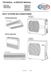
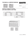
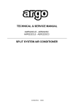
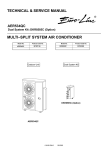
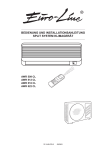
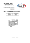
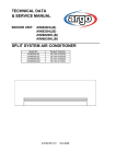
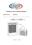
TECHNICAL DATA
& SERVICE MANUAL
®
OUTDOOR UNIT: AER518SC
AER518SCL
AER522SC
SPLIT SYSTEM AIR CONDITIONER
Model No.
AER518SC
AER518SCL
AER522SC
Product Code No.
387007114
387007140
387007142
0.8180.267.0
05/2002
• Ground the unit following local electrical codes.
• The Yellow/Green wire cannot be used for any connection
different from the ground connection.
• Connect all wiring tightly. Loose wiring may cause overheating
at connection points and a possible fire hazard.
• Do not allow wiring to touch the refrigerant tubing, compressor,
or any moving parts of the fan.
• Do not use multi-core cable when wiring the power supply and
control lines. Use separate cables for each type of line.
IMPORTANT!
Please read before installation
This air conditioning system meets strict safety and operating
standards.
For the installer or service person, it is important to install or
service the system so that it operates safely and efficiently.
For safe installation and trouble-free operation, you must:
• Carefully read this instruction booklet before beginning.
• Follow each installation or repair step exactly as shown.
• Observe all local, state and national electrical codes.
• Pay close attention to all warning and caution notices given in
this manual.
•The unit must be supplied with a dedicated electrical line.
When transporting
Be careful when picking up and moving the indoor and outdoor
units. Get a partner to help, and bend your knees when lifting to
reduce strain on your back. Sharp edges or thin aluminium fins on
the air conditioner can cut your fingers.
WARNING
When installing...
... In a ceiling or wall
Make sure the ceiling/wall is strong enough to hold the unit-weight.
It may be necessary to build a strong wooden or metal frame to
provide added support.
This symbol refers to a hazard or unsafe practice which can result
in severe personal injury or death.
... In a room
Properly insulate any tubing run inside a room to prevent
"sweating", which can cause dripping and water damage to walls
and floors.
CAUTION
This symbol refers to a hazard or unsafe practice which can result
in personal injury or product or property damage.
... In moist or uneven locations
Use a raised concrete base to provide a solid level foundation for
the outdoor unit.
This prevents damage and abnormal vibrations.
If necessary, get help
These instructions are all you need for most installation sites and
maintenance conditions.
If you require help for a special problem, contact our sale/service
outlet or your certified dealer for additional instructions.
... In area with strong winds
Securely anchor the outdoor unit down with bolts and a metal
frame. Provide a suitable air baffle.
In case of improper installation
The manufacturer shall in no way be responsible for improper
installation or maintenance service, including failure to follow the
instructions in this document.
... In a snowy area (for heat pump-type systems)
Install the outdoor unit on a raised platform that is higher than
drifting snow. Provide snow vents.
SPECIAL PRECAUTIONS
When connecting refrigerant tubing
• Keep all tubing runs as short as possible.
• Use the flare method for connecting tubing.
• Apply refrigerant lubricant to the matching surfaces of the flare
and union tubes before connecting them; screw by hand and
then tighten the nut with a torque wrench for a leak-free
connection.
• Check carefully for leaks before starting the test run.
• During installation, connect before the refrigerant system and
then the wiring one; proceed in the reverse orden when removing
the units.
WARNING
When wiring
ELECTRICAL SHOCK CAN CAUSE SEVERE
PERSONAL INJURY OR DEATH. ONLY A QUALIFIED,
EXPERIENCED ELECTRICIANS SHOULD ATTEMPT
TO WIRE THIS SYSTEM.
NOTE:
Depending on the system type, liquid and gas lines may be either
narrow or wide. Therefore, to avoid confusion, the refrigerant
tubing for your particular model is specified as narrow tube for
liquid, wide tube for gas.
• Do not supply power to the unit until all wiring and tubing are
completed or reconnected and checked, to ensure the grounding.
• Highly dangerous electrical voltages are used in this system.
Carefully refer to the wiring diagram and these instructions when
wiring.
Improper connections and inadequate grounding can cause
accidental injury and death.
When servicing
• Turn the power OFF at the main power board before opening
the unit to check or repair electrical parts and wiring.
• Keep your fingers and clothing away from any moving parts.
• Clean up the site after the work, remembering to check that no
metal scraps or bits of wiring have been left inside the unit being
serviced.
• Ventilate the room during the installation or testng the refrigeration
system; make sure that, after the installation, no gas leaks are
present, because this could produce toxic gas and dangerous
if in contact with flames or heat-sources.
2
Table of Contents
Page
1. OPERATING RANGE
4
2. SPECIFICATIONS
5
5
8
2-1 Unit specifications
2-2 Major Component specifications
3. DIMENSIONAL DATA
11
4. REFRIGERANT FLOW DIAGRAM
13
5. PERFORMANCE DATA
14
14
18
5-1 Performance Charts
5-2 Cooling Capacity
21
21
24
26
6. ELECTRICAL DATA
6-1 Electrical characteristics
6-2 Electric Wiring Diagram
6-3 System Wiring Diagram
3
1. OPERATING RANGE
Cooling
Temperature
Maximum
Minimum
Indoor Air Intake Temp.
32°C D.B. / 23°C W.B.
19°C D.B. / 14°C W.B.
Outdoor Air Intake Temp.
43°C D.B.
(*)19°C D.B.
(*) SCL MODEL : -15°C D.B.
4
2. SPECIFICATIONS
2-1 Unit Specifications
AER518SC
Power source
220 - 240V ~ 50Hz
Voltage rating
230V
Performance *
Capacity
AWR518CL
kW
BTU/h
m³/h
Liters/h
Air circulation (High)
Moisture removal (High)
Electrical Rating
Available voltage range
Running amperes
Power input
Power factor
C.O.P.
Compressor locked rotor amperes
V
A
W
%
W/W
A
Features
Fan speed
Compressor
Refrigerant / Amount charged at shipment
Refrigerant control
Operation Sound
Hi
Refrigerant tubing connections
Max. allowable tubing length at shipment
Refrigerant
Narrow tube
tube diameter
Wide tube
Dimensions & Weight
Unit dimensions
Package dimensions
Weight
g
dB-A
m
mm(in.)
mm(in.)
Cooling
5,00
17063
760
2,3
Cooling
198 ~ 264
10,00
2200
96
2,3
46
1(Hi)
Rotary (Hermetic)
R407C / 1760
Capillary tube
64
Flare type
7,5
6,35 (1/4")
12,7(1/2")
630
mm
830
mm
305
mm
713
mm
994
mm
413
mm
52
kg
57
kg
3
0,29
m
DATA SUBJECT TO CHANGE WITHOUT NOTICE
Height
Width
Depth
Height
Width
Depth
Net
Shipping
Shipping volume
Remarks:
Rating conditions are:
Cooling: Indoor air temperature 27°C D.B. / 19°C W.B.
Outdoor air temperature 35°C D.B. / 24°C W.B.
Heating: Indoor air temperature 20°C D.B.
Outdoor air temperature 7°C D.B. / 6°C W.B.
5
AER518SCL
Power source
220 - 240V ~ 50Hz
Voltage rating
230V
Performance *
Capacity
AWR518CL
kW
BTU/h
m³/h
Liters/h
Air circulation (High)
Moisture removal (High)
Electrical Rating
Available voltage range
Running amperes
Power input
Power factor
C.O.P.
Compressor locked rotor amperes
V
A
W
%
W/W
A
Features
Fan speed
Compressor
Refrigerant / Amount charged at shipment
Refrigerant control
Operation Sound
Hi
Refrigerant tubing connections
Max. allowable tubing length at shipment
Refrigerant
Narrow tube
tube diameter
Wide tube
Dimensions & Weight
Unit dimensions
Package dimensions
Weight
g
dB-A
m
mm(in.)
mm(in.)
Cooling
5,00
17063
760
2,3
Cooling
198 ~ 264
10,00
2200
96
2,3
46
1(Hi)
Rotary (Hermetic)
R407C / 1670
Capillary tube
64
Flare type
7,5
6,35 (1/4")
12,7(1/2")
630
mm
830
mm
305
mm
713
mm
994
mm
413
mm
52
kg
57
kg
3
0,29
m
DATA SUBJECT TO CHANGE WITHOUT NOTICE
Height
Width
Depth
Height
Width
Depth
Net
Shipping
Shipping volume
Remarks:
Rating conditions are:
Cooling: Indoor air temperature 27°C D.B. / 19°C W.B.
Outdoor air temperature 35°C D.B. / 24°C W.B.
Heating: Indoor air temperature 20°C D.B.
Outdoor air temperature 7°C D.B. / 6°C W.B.
6
AER522SC
Power source
220 - 240V ~ 50Hz
Voltage rating
230V
Performance *
Capacity
Cooling
AWR518CL
Air circulation (High)
Moisture removal (High)
Cooling
Electrical Rating
Available voltage range
Running amperes
Power input
Power factor
C.O.P.
Compressor locked rotor amperes
V
A
W
%
W/W
A
Features
Fan speed
Compressor
Refrigerant / Amount charged at shipment
Refrigerant control
Operation Sound
Hi
Refrigerant tubing connections
Max. allowable tubing length at shipment
Refrigerant
Narrow tube
tube diameter
Wide tube
Dimensions & Weight
Unit dimensions
Package dimensions
Weight
5,90
20134
830
3,3
kW
BTU/h
m³/h
Liters/h
g
dB-A
m
mm(in.)
mm(in.)
198 ~ 264
13,00
2750
92
2,1
70
1(Hi)
Rotary (Hermetic)
R407C / 2400
Capillary tube
67
Flare type
7,5
6,35 (1/4")
15,88 (5/8")
835
mm
850
mm
305
mm
913
mm
1000
mm
400
mm
67,0
kg
76,0
kg
3
0,37
m
DATA SUBJECT TO CHANGE WITHOUT NOTICE
Height
Width
Depth
Height
Width
Depth
Net
Shipping
Shipping volume
Remarks:
Rating conditions are:
Cooling: Indoor air temperature 27°C D.B. / 19°C W.B.
Outdoor air temperature 35°C D.B. / 24°C W.B.
Heating: Indoor air temperature 20°C D.B.
Outdoor air temperature 7°C D.B. / 6°C W.B.
7
2-2 Major Component Specifications
Outdoor Unit:
AER518SC
Compressor
Type
Compressor model
Nominal output
Compressor oil…Amount
Coil resistance (Ambient temp. 25°C)
Safety devices
Run capacitor
W
cc.
Ω
Type
Overload relay
Operating Temp. Open
°C
Close
°C
Operating amp.(Ambient temp.25°C)
µF
VAC
Fan & Fan Motor
Type
Q'ty ……. Dia.
Fan motor model…Q'ty
No. Of poles…rpm (230 V, High)
Nominal output
Coil resistance (Ambient temp. 20 °C )
Safety devices
°C
°C
µF
VAC
Propeller
1…. Ø 400
SG6S-51B5P OR / KFG6S-51SB5P - 1
6…900 / 6...912
50 / 42,7
BRN-WHT: 89,1 / 98,5
WHT-YEL: 111,8 / 120,5
YEL - PNK : 55,9 / 60,5
Internal thermal protector
130 ± 8 / 130 ± 5
83 ± 15
2
440
mm
m2
Aluminium plate fin / Copper tube
2
1,8
0,508
W
Ω
Ω
Ω
Type
Operating temp. Open
Close
Run capacitor
Heat Exch. Coil
Coil
Rows
Fin pitch
Face area
Rotary (Hermetic)
80807045B C-2RN170H5W
1700
FV68S…800
C-R: 1,353
C-S: 3,422
Internal protector
Automatic opening
Automatic reclosining
40
400
Acrylic baked-on enamel finish
External Finish
DATA SUBJECT TO CHANGE WITHOUT NOTICE
8
Outdoor Unit:
AER518SCL
Compressor
Type
Compressor model
Nominal output
Compressor oil…Amount
Coil resistance (Ambient temp. 25°C)
Safety devices
Run capacitor
W
cc.
Ω
Ω
Type
Overload relay
Operating Temp. Open
°C
Close
°C
Operating amp.(Ambient temp.25°C)
µF
VAC
Crank case heater
Fan & Fan Motor
Type
Q'ty ……. Dia.
Fan motor model…Q'ty
No. Of poles…rpm (230 V, High)
Nominal output
Coil resistance (Ambient temp. 20 °C )
Safety devices
W
Ω
Ω
Type
Operating temp. Open
Close
Run capacitor
Heat Exch. Coil
Coil
Rows
Fin pitch
Face area
Rotary (Hermetic)
80242335 C-RN190H5B
1900
FV68S…2100
C-R: 0,921
C-S: 2,843
Internal protector
Automatic opening
Automatic reclosining
40
400
240 V - 30 W
Propeller
1…. Ø 400
SMEN 5192672 OR / KFG6S-51SA5P - 1
6…910 / 6…908
43 / 40
BRN-WHT: 83,4 / 98,5
WHT-PNK: 218,7 / 201
°C
°C
µF
VAC
Internal thermal protector
130 ± 5
83 ± 15
2
440
mm
m2
Aluminium plate fin / Copper tube
2
1,8
0,508
Acrylic baked-on enamel finish
External Finish
DATA SUBJECT TO CHANGE WITHOUT NOTICE
9
Outdoor Unit:
AER522SC
Compressor
Type
Compressor model
Nominal output
Compressor oil…Amount
Coil resistance (Ambient temp. 25°C)
Safety devices
Run capacitor
W
cc.
Ω
Ω
Type
Overload relay
Operating Temp. Open
°C
Close
°C
Operating amp.(Ambient temp.25°C)
µF
VAC
Crank case heater
Fan & Fan Motor
Type
Q'ty ……. Dia.
Fan motor model…Q'ty
No. Of poles…rpm (230 V, High)
Nominal output
Coil resistance (Ambient temp. 20 °C )
Safety devices
°C
°C
µF
VAC
Propeller
1…. Ø 460
KFC6S-51B5P OR / KFG6S-51SA5P - 1
6…860 / 6…856
50 / 62,6
BRN-WHT: 95,9 / 98,1
WHT-YEL: 55,4 / 56,7
YEL - PNK : 7,2 / 7,4
Internal thermal protector
130 ± 5
83 ± 15
5,0
440
mm
m2
Aluminium plate fin / Copper tube
2
2
0.610
W
Ω
Ω
Ω
Type
Operating temp. Open
Close
Run capacitor
Heat Exch. Coil
Coil
Rows
Fin pitch
Face area
Rotary (Hermetic)
80244035 C-RN220H5A
2200
FV68S…1350
C-R: 0,777
C-S: 2,408
External protector
Internal protector
OL-D24
Automatic opening
150 ± 5
Automatic reclosining
63 ± 10
Trip in 6 to 16 sec.at 59 A
40
400
240 V - 30 W
Acrylic baked-on enamel finish
External Finish
DATA SUBJECT TO CHANGE WITHOUT NOTICE
10
3. DIMENSIONAL DATA
Outdoor Unit:
AER518SC
AER518SCL
538
146
337
307
Air intake
4 – ø12 holes
Air discharge
Wide tube service valve
ø12.7 (1/2")
Narrow tube service valve
ø6.35 (1/4")
305
19
95 61
630
830
Unit : mm
11
AER522SC
Outdoor Unit:
Air intake
325
20
20
Air discharge
130
620
100
55
Wide tube service valve ø15.88 (5/8")
Narrow tube service valve ø6.35 (1/4")
6 – ø3.1 holes
Check port ø6.35 (1/4")
850
250
285
86 73
229
57
835
560
250
86
88
155
Unit : mm
12
4. REFRIGERANT FLOW DIAGRAM
Indoor Unit:
Outdoor Unit:
AER518SC
Indoor Unit:
Outdoor Unit:
AER518SCL
13
Indoor Unit:
Outdoor Unit:
14
AER522SC
5. PERFORMANCE DATA
5-1 Performance charts
AER518SC
n
Cooling Characteristics
15
Indoor inlet air
D.B. (°C)
14
Operating current (A)
13
32
12
27
11
19
10
9
8
7
6
5
20
25
30
35
40
45
Outdoor inlet air D.B. temp. (°C)
0,60
Indoor inlet air
D.B. (°C)
32
Low pressure at wide tube service valve MPa
0,50
27
19
0,40
0,30
0,20
0,10
0,00
20
25
30
35
40
45
Outdoor inlet air D.B. (°C)
Overload prevention operates to protect the air conditioner when outdoor ambient temperature
reaches extremely high values in heating mode.
Points of Rating condition
Data referred to
AWR518CL
15
AER518SCL
n
Cooling Characteristics
15
Indoor inlet air
D.B. (°C)
14
13
32
Operating current (A)
12
27
19
11
10
9
8
7
6
5
20
25
30
35
40
45
Outdoor inlet air D.B. temp. (°C)
Indoor inlet air
D.B. (°C)
0,60
32
Low pressure at wide tube service valve MPa
0,50
27
19
0,40
0,30
0,20
0,10
0,00
20
25
30
35
40
45
Outdoor inlet air D.B. (°C)
Overload prevention operates to protect the air conditioner when outdoor ambient temperature
reaches extremely high values in heating mode.
Points of Rating condition
Data referred to
AWR518CL
16
AER522SC
n Cooling Characteristics
15
Indoor inlet air
D.B. (°C)
14
13
Operating current (A)
32
12
27
11
19
10
9
8
7
6
5
20
25
30
35
40
45
Outdoor inlet air D.B. temp. (°C)
Indoor inlet air
D.B. (°C)
0,60
32
Low pressure at wide tube service valve MPa
0,50
27
19
0,40
0,30
0,20
0,10
0,00
20
25
30
35
40
45
Outdoor inlet air D.B. (°C)
Overload prevention operates to protect the air conditioner when outdoor ambient temperature
reaches extremely high values in heating mode.
Points of Rating condition
Data referred to AWR522CL
17
5-2 Cooling Capacity
OUTDOOR UNIT:
INDOOR UNIT:
AER518SC
AWR518CL
220 - 240V ~ 50Hz
RATING CAPACITY
COMP. POWER INPUT
AIR FLOW RATE
EVAPORATOR
ENT.TEMP. °C
W.B.
D.B.
15
17
19
21
23
TC:
SHC:
CM:
NOTE:
5,00 kW
2,044 kW
760 m³/h
moisture removal
max comp input
CONDENSER
OUTDOOR AMBIENT TEMP. °C
20
25
30
35
TC
5,05
4,74
4,60
4,38
CM
1,43
1,59
1,76
1,92
21
SHC
3,50
3,25
3,18
3,08
23
SHC
3,96
3,68
3,61
3,50
25
SHC
4,40
4,10
4,02
3,91
27
SHC
4,85
4,54
4,45
4,34
29
SHC
5,05
4,74
4,60
4,38
31
SHC
5,05
4,74
4,60
4,38
TC
5,41
5,13
4,93
4,70
CM
1,49
1,66
1,82
1,98
21
SHC
3,02
2,84
2,76
2,65
23
SHC
3,48
3,27
3,17
3,07
25
SHC
3,93
3,70
3,60
3,49
27
SHC
4,39
4,13
4,01
3,90
29
SHC
4,85
4,56
4,43
4,33
31
SHC
5,28
4,99
4,85
4,70
TC
5,75
5,43
5,25
5,00
CM
1,55
1,72
1,88
2,04
21
SHC
2,54
2,38
2,30
2,20
23
SHC
2,99
2,80
2,73
2,62
25
SHC
3,45
3,21
3,14
3,03
27
SHC
3,88
3,62
3,57
3,39
29
SHC
4,34
4,02
3,98
3,87
31
SHC
4,80
4,45
4,40
4,29
TC
6,05
5,76
5,57
5,30
CM
1,84
1,96
2,08
2,20
23
SHC
2,48
2,35
2,27
2,16
25
SHC
2,94
2,75
2,68
2,59
27
SHC
3,39
3,17
3,11
3,00
29
SHC
3,85
3,57
3,52
3,42
31
SHC
4,28
3,99
3,95
3,84
TC
6,45
6,09
5,89
5,57
CM
2,14
2,21
2,28
2,35
25
SHC
2,42
2,28
2,21
2,09
27
SHC
2,88
2,67
2,62
2,50
29
SHC
3,33
3,07
3,04
2,92
31
SHC
3,79
3,51
3,47
3,34
TOTAL COOLING CAPACITY
kW
SENSIBLE HEAT CAPACITY
kW
COMPRESSOR INPUT
kW
Data referred to
AWR518CL
18
2,3 l/h
2,494 kW
40
4,11
2,09
2,95
3,37
3,78
4,11
4,11
4,11
4,41
2,15
2,52
2,93
3,36
3,77
4,20
4,41
4,70
2,21
2,07
2,49
2,91
3,33
3,75
4,16
4,98
2,32
2,03
2,46
2,88
3,29
3,72
5,21
2,42
1,96
2,37
2,79
3,21
43
3,79
2,25
2,79
3,22
3,63
3,79
3,79
3,79
4,07
2,31
2,36
2,78
3,20
3,62
4,03
4,07
4,33
2,37
1,91
2,34
2,75
3,17
3,59
4,01
4,59
2,43
1,88
2,30
2,72
3,14
3,57
4,85
2,49
1,83
2,24
2,66
3,09
OUTDOOR UNIT:
INDOOR UNIT:
AER518SCL
AWR518CL
220 - 240V ~ 50Hz
RATING CAPACITY
COMP. POWER INPUT
AIR FLOW RATE
EVAPORATOR
ENT.TEMP. °C
W.B.
D.B.
15
17
19
21
23
TC:
SHC:
CM:
NOTE:
5,00 kW
2,043 kW
760 m³/h
moisture removal
max comp input
CONDENSER
OUTDOOR AMBIENT TEMP. °C
20
25
30
35
TC
5,05
4,74
4,60
4,38
CM
1,43
1,59
1,76
1,92
21
SHC
3,50
3,25
3,18
3,08
23
SHC
3,96
3,68
3,61
3,50
25
SHC
4,40
4,10
4,02
3,91
27
SHC
4,85
4,54
4,45
4,34
29
SHC
5,05
4,74
4,60
4,38
31
SHC
5,05
4,74
4,60
4,38
TC
5,41
5,13
4,93
4,70
CM
1,49
1,65
1,82
1,98
21
SHC
3,02
2,84
2,76
2,65
23
SHC
3,48
3,27
3,17
3,07
25
SHC
3,93
3,70
3,60
3,49
27
SHC
4,39
4,13
4,01
3,90
29
SHC
4,85
4,56
4,43
4,33
31
SHC
5,28
4,99
4,85
4,70
TC
5,75
5,43
5,25
5,00
CM
1,55
1,72
1,88
2,04
21
SHC
2,54
2,38
2,30
2,20
23
SHC
2,99
2,80
2,73
2,62
25
SHC
3,45
3,21
3,14
3,03
27
SHC
3,88
3,62
3,57
3,39
29
SHC
4,34
4,02
3,98
3,87
31
SHC
4,80
4,45
4,40
4,29
TC
6,05
5,76
5,57
5,30
CM
1,72
1,86
2,00
2,15
23
SHC
2,48
2,35
2,27
2,16
25
SHC
2,94
2,75
2,68
2,59
27
SHC
3,39
3,17
3,11
3,00
29
SHC
3,85
3,57
3,52
3,42
31
SHC
4,28
3,99
3,95
3,84
TC
6,45
6,09
5,89
5,57
CM
1,88
2,00
2,13
2,25
25
SHC
2,42
2,28
2,21
2,09
27
SHC
2,88
2,67
2,62
2,50
29
SHC
3,33
3,07
3,04
2,92
31
SHC
3,79
3,51
3,47
3,34
TOTAL COOLING CAPACITY
kW
SENSIBLE HEAT CAPACITY
kW
COMPRESSOR INPUT
kW
Data referred to
AWR518CL
19
2,3 l/h
2,493 kW
40
4,11
2,08
2,95
3,37
3,78
4,11
4,11
4,11
4,41
2,15
2,52
2,93
3,36
3,77
4,20
4,41
4,70
2,21
2,07
2,49
2,91
3,33
3,75
4,16
4,98
2,29
2,03
2,46
2,88
3,29
3,72
5,21
2,37
1,96
2,37
2,79
3,21
43
3,79
2,25
2,79
3,22
3,63
3,79
3,79
3,79
4,07
2,31
2,36
2,78
3,20
3,62
4,03
4,07
4,33
2,37
1,91
2,34
2,75
3,17
3,59
4,01
4,59
2,43
1,88
2,30
2,72
3,14
3,57
4,85
2,49
1,83
2,24
2,66
3,09
OUTDOOR UNIT:
INDOOR UNIT:
AER522SC
AWR522CL
220 - 240V ~ 50Hz
RATING CAPACITY
COMP. POWER INPUT
AIR FLOW RATE
EVAPORATOR
ENT.TEMP. °C
W.B.
D.B.
15
17
19
21
23
TC:
SHC:
CM:
NOTE:
5,90 kW
2,551 kW
830 m³/h
moisture removal
max comp input
CONDENSER
OUTDOOR AMBIENT TEMP. °C
20
25
30
35
TC
5,96
5,59
5,43
5,17
CM
1,80
2,00
2,20
2,40
21
SHC
4,14
3,83
3,76
3,63
23
SHC
4,67
4,35
4,26
4,13
25
SHC
5,19
4,84
4,75
4,62
27
SHC
5,73
5,35
5,25
5,12
29
SHC
5,96
5,59
5,43
5,17
31
SHC
5,96
5,59
5,43
5,17
TC
6,38
6,05
5,82
5,54
CM
1,88
2,08
2,28
2,47
21
SHC
3,56
3,35
3,26
3,13
23
SHC
4,10
3,85
3,75
3,62
25
SHC
4,64
4,37
4,25
4,12
27
SHC
5,18
4,87
4,73
4,60
29
SHC
5,72
5,39
5,23
5,10
31
SHC
6,23
5,89
5,72
5,54
TC
6,79
6,41
6,20
5,90
CM
1,96
2,15
2,35
2,55
21
SHC
3,00
2,81
2,72
2,59
23
SHC
3,53
3,30
3,22
3,09
25
SHC
4,07
3,78
3,71
3,58
27
SHC
4,58
4,27
4,21
3,59
29
SHC
5,12
4,75
4,69
4,57
31
SHC
5,66
5,25
5,19
5,07
TC
7,14
6,80
6,57
6,26
CM
2,15
2,32
2,50
2,67
23
SHC
2,93
2,77
2,68
2,55
25
SHC
3,47
3,25
3,17
3,05
27
SHC
4,00
3,74
3,67
3,54
29
SHC
4,54
4,21
4,16
4,04
31
SHC
5,05
4,71
4,66
4,53
TC
7,61
7,18
6,95
6,57
CM
2,34
2,49
2,64
2,79
25
SHC
2,86
2,69
2,60
2,46
27
SHC
3,40
3,15
3,09
2,95
29
SHC
3,93
3,63
3,59
3,45
31
SHC
4,47
4,14
4,09
3,94
TOTAL COOLING CAPACITY
kW
SENSIBLE HEAT CAPACITY
kW
COMPRESSOR INPUT
kW
Data referred to
AWR522CL
20
3,3 l/h
3,101 kW
40
4,85
2,60
3,48
3,98
4,46
4,85
4,85
4,85
5,21
2,67
2,98
3,46
3,96
4,45
4,95
5,21
5,54
2,75
2,44
2,94
3,44
3,92
4,43
4,91
5,87
2,85
2,40
2,90
3,40
3,89
4,39
6,14
2,95
2,31
2,80
3,30
3,78
43
4,48
2,79
3,30
3,80
4,28
4,48
4,48
4,48
4,80
2,87
2,78
3,28
3,77
4,27
4,76
4,80
5,10
2,95
2,26
2,76
3,25
3,75
4,23
4,73
5,41
3,02
2,22
2,72
3,21
3,71
4,21
5,72
3,10
2,15
2,64
3,14
3,64
6. ELECTRICAL DATA
6-1 Electrical characteristics
OUTDOOR UNIT:
AER518SC
COOLING
Indoor Unit
Fan Motor
performance at
Rating conditions
Full load conditions
Running Amps.
Power input
Running Amps.
Power input
A
Kw
A
Kw
0,37
0,070
0,37
0,070
Outdoor unit
Fan Motor
Compressor
230V 1-Phase 50 Hz
0,40
9,23
0,086
2,044
0,40
11,23
0,086
2,494
Rating Conditions:
Indoor Air Temperature 27°C D.B. / 19°C W.B.
Outdoor Air Temperature 35°C D.B.
Full Load Conditions: Indoor Air Temperature 32°C D.B. / 23°C W.B.
Outdoor Air Temperature 43°C D.B.
NOTE: Data referred to indoor unit
AWR518CL
model.
For other indoor unit models there could be the same differences.
21
Complete Unit
10,0
2,200
12,0
2,650
OUTDOOR UNIT:
AER518SCL
COOLING
Indoor Unit
Fan Motor
performance at
Rating conditions
Full load conditions
Running Amps.
Power input
Running Amps.
Power input
A
Kw
A
Kw
0,37
0,070
0,37
0,070
Outdoor unit
Fan Motor
Compressor
230V 1-Phase 50 Hz
0,41
9,2
0,087
2,043
0,41
11,2
0,087
2,493
Rating Conditions:
Indoor Air Temperature 27°C D.B. / 19°C W.B.
Outdoor Air Temperature 35°C D.B.
Full Load Conditions: Indoor Air Temperature 32°C D.B. / 23°C W.B.
Outdoor Air Temperature 43°C D.B.
NOTE: Data referred to indoor unit
AWR518CL
model.
For other indoor unit models could be the same difference.
22
Complete Unit
10,0
2,200
12,0
2,650
OUTDOOR UNIT:
AER522SC
COOLING
Indoor Unit
Fan Motor
performance at
Rating conditions
Full load conditions
Running Amps.
Power input
Running Amps.
Power input
A
Kw
A
Kw
0,39
0,075
0,39
0,075
Outdoor unit
Fan Motor
Compressor
230V 1-Phase 50 Hz
0,55
12,1
0,124
2,551
0,55
14,1
0,124
3,101
Rating Conditions:
Indoor Air Temperature 27°C D.B. / 19°C W.B.
Outdoor Air Temperature 35°C D.B.
Full Load Conditions: Indoor Air Temperature 32°C D.B. / 23°C W.B.
Outdoor Air Temperature 43°C D.B.
NOTE: Data referred to indoor unit
AWR522CL
model.
For other indoor unit models could be the same difference.
23
Complete Unit
13,0
2,750
15,0
3,300
AER518SC
6-2 Electric Wiring Diagram
OUTDOOR UNIT:
AER518SCL
OUTDOOR UNIT:
24
AER522SC
OUTDOOR UNIT:
25
6-3 System Wiring Diagram
26
Via Varese, 90 - 21013 Gallarate - Va - Italy
Tel. +39 0331 755111 - Fax +39 0331 776240
www.argoclima.it