1
6263 RM-207 / 6267 RM-210
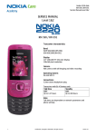
Service Manual Level 1&2
SERVICE MANUAL
Level 1&2
RM-207
RM-210
Transceiver characteristics:
Band:
EGSM: Quad-band 850/900/1800/1900MHz
RM-210 only: WCDMA: 850/2100MHz
RM-207 only: WCDMA: 1700MHz
Display:
Main L CD: 5.588cm QVGA (2.2”) (240x320 pixel); 16M colors
Second LCD: 3.4544cm (1.36”) 128x160
Camera:
Camera: 2.0 Megapixel, Flash and 8x zoom
RM-210 only: 2nd Camera: CIF ACME
Operating System:
Series 40
Connections:
Wireless: Bluetooth
Connector: Mini USB Connector; AV Connector
Memory:
MicroSD™ (max 4GB)
Transceiver with BL-5c Li-Ion battery pack
Page
1 (21)
Talk time
Standby
Note
GSM: up to 6.5h
WCDMA: up to 2.75h
up to 10days
Depends on network
parameters
CONFIDENTIAL
Copyright © 2007 NOKIA. All rights reserved.
ISSUE 4
6263 RM-207 / 6267 RM-210
Service Manual Level 1&2
TABLE OF CONTENTS
1.
2.
3.
4.
5.
6.
7.
8.
9.
10.
11.
12.
13.
14.
Page
Page
CHANGE HISTORY
COPYRIGHT
WARNINGS AND CAUTIONS ESD PROTECTION
CARE AND MAINTENANCE
BATTERY INFORMATION
EXPLODED VIEW
SPARE PARTS OVERVIEW
LEVEL 2 SOLDER COMPONENTS
SERVICE TOOLS
SW-UPDATE
UPPER BLOCK DISASSEMBLY
UPPER BLOCK ASSEMBLY HINTS LOWER BLOCK DISASSEMBLY
2 (21)
CONFIDENTIAL
Copyright © 2007 NOKIA. All rights reserved.
3
3
4
4
5
5
6
7
8
9
10
11
16
17
ISSUE 4
6263 RM-207 / 6267 RM-210
Service Manual Level 1&2
1. CHANGE HISTORY
Status
Version No.
Date
Comments
Draft
0.1
15.Jun.2007
Initial draft
Approved
2.0
28.Jun.2007
Approval
Approved
3.0
23.July.2007
Exploded view & Spare Parts overview changed (A3 Assy structure)
Approved
4.0
10.Aug.2007
Exploded view & Spare Parts overview changed (A2 Assy added)
Approved
5.0
28.Aug.2007
6263 RM-207 added
Approved
6.0
12.Oct.2007
Exploded view & Spare Parts overview changed (I9998 added)
Approved
7.0
05.Nov.2007
Exploded view & Spare Parts overview update (I0014 single available)
The purpose of this document is to help NOKIA service levels 1 and 2 workshop technicians to carry out service to
NOKIA products. This Service Manual is to be used only by authorized NOKIA service suppliers, and the content of it is
confidential. Please note that NOKIA provides also other guidance documents (e.g. Service Bulletins) for service suppliers, follow these regularly and comply with the given instructions.
While every endeavor has been made to ensure the accuracy of this document, some errors may exist.
If you find any errors or if you have further suggestions, please notify NOKIA using the address below:
CMO Operation & Logistics
Training and Vendor Development
Multimedia Creation & Support
mailto:[email protected]
Please keep in mind also that this documentation is continuously being updated and modified, so watch always out
for the newest version.
2. COPYRIGHT
Copyright © 2007 Nokia. All rights reserved.
Reproduction, transfer, distribution or storage of part or all of the contents in this document in any form
without the prior written permission of Nokia is prohibited.
Nokia, Nokia Connecting People, and Nokia X and Y are trademarks or registered trademarks of Nokia
Corporation. Other product and company names mentioned herein may be trademarks or tradenames of
their respective owners.
Nokia operates a policy of continuous development. Nokia reserves the right to make changes and
improvements to any of the products described in this document without prior notice.
Under no circumstances shall Nokia be responsible for any loss of data or income or any special, incidental,
consequential or indirect damages howsoever caused.
The contents of this document are provided “as is”. Except as required by applicable law, no warranties of
any kind, either express or implied, including, but not limited to, the implied warranties of merchantability
and fitness for a particular purpose, are made in relation to the accuracy, reliability or contents of this
document. Nokia reserves the right to revise this document or withdraw it at any time without prior notice.
The availability of particular products may vary by region.
IMPORTANT
This document is intended for use by qualified service personnel only.
Page
3 (21)
CONFIDENTIAL
Copyright © 2007 NOKIA. All rights reserved.
ISSUE 4
6263 RM-207 / 6267 RM-210
Service Manual Level 1&2
3. WARNINGS AND CAUTIONS
Warnings and Cautions
Please refer to the phone’s user guide for instructions relating to operation, care and maintenance including important safety information. Note also the following:
Warnings:
1. CARE MUST BE TAKEN ON INSTALLATION IN VEHICLES FITTED WITH ELECTRONIC ENGINE MANAGEMENT SYSTEMS
AND ANTI–SKID BRAKING SYSTEMS. UNDER CERTAIN FAULT CONDITIONS, EMITTED RF ENERGY CAN AFFECT THEIR
OPERATION. IF NECESSARY, CONSULT THE VEHICLE DEALER/MANUFACTURER TO DETERMINE THE IMMUNITY OF VEHICLE ELECTRONIC SYSTEMS TO RF ENERGY.
2. THE HANDPORTABLE TELEPHONE MUST NOT BE OPERATED IN AREAS LIKELY TO CONTAIN POTENTIALLY EXPLOSIVE
ATMOSPHERES, EG PETROL STATIONS (SERVICE STATIONS), BLASTING AREAS ETC.
3. OPERATION OF ANY RADIO TRANSMITTING EQUIPMENT, INCLUDING CELLULAR TELEPHONES, MAY INTERFERE WITH
THE FUNCTIONALITY OF INADEQUATELY PROTECTED MEDICAL DEVICES. CONSULT A PHYSICIAN OR THE MANUFACTURER OF THE MEDICAL DEVICE IF YOU HAVE ANY QUESTIONS. OTHER ELECTRONIC EQUIPMENT MAY ALSO BE SUBJECT TO
INTERFERENCE.
Cautions:
1. Servicing and alignment must be undertaken by qualified personnel only.
2. Ensure all work is carried out at an anti–static workstation and that an anti–static wrist strap is worn.
3. Use only approved components as specified in the parts list.
4. Ensure all components, modules screws and insulators are correctly re–fitted after servicing and alignment.
5. Ensure all cables and wires are repositioned correctly.
4. ESD PROTECTION
Nokia requires that service points have sufficient ESD protection (against static electricity) when
servicing the phone.
Any product of which the covers are removed must be handled with ESD protection. The SIM card
can be replaced without ESD protection if the product is otherwise ready for use.
To replace the covers ESD protection must be applied.
All electronic parts of the product are susceptible to ESD. Resistors, too, can be damaged by static
electricity discharge.
All ESD sensitive parts must be packed in metallized protective bags during shipping and handling
outside any ESD Protected Area (EPA).
Every repair action involving opening the product or handling the product components must be
done under ESD protection.
ESD protected spare part packages MUST NOT be opened/closed out of an ESD Protected Area.
For more information and local requirements about ESD protection and ESD Protected Area, contact
your local Nokia After Market Services representative.
Page
4 (21)
CONFIDENTIAL
Copyright © 2007 NOKIA. All rights reserved.
ISSUE 4
6263 RM-207 / 6267 RM-210
Service Manual Level 1&2
5. CARE AND MAINTENANCE
This product is of superior design and craftsmanship and should be treated with care. The suggestions below
will help you to fulfil any warranty obligations and to enjoy this product for many years.
• Keep the phone and all its parts and accessories out of the reach of small children.
• Keep the phone dry. Precipitation, humidity and all types of liquids or moisture can contain minerals that
will corrode electronic circuits.
• Do not use or store the phone in dusty, dirty areas. Its moving parts can be damaged.
• Do not store the phone in hot areas. High temperatures can shorten the life of electronic devices, damage
batteries, and warp or melt certain plastics.
• Do not store the phone in cold areas. When it warms up (to its normal temperature), moisture can form
inside, which may damage electronic circuit boards.
• Do not drop, knock or shake the phone. Rough handling can break internal circuit boards.
• Do not use harsh chemicals, cleaning solvents, or strong detergents to clean the phone.
• Do not paint the phone. Paint can clog the moving parts and prevent proper operation.
• Use only the supplied or an approved replacement antenna. Unauthorised antennas, modifications or
attachments could damage the phone and may violate regulations governing radio devices.
All of the above suggestions apply equally to the product, battery, charger or any accessory.
6. BATTERY INFORMATION
Note: A new battery’s full performance is achieved only after two or three complete charge and discharge cycles!
The battery can be charged and discharged hundreds of times but it will eventually wear out.
When the operating time (talk-time and standby time) is noticeably shorter than normal, it is time to buy a new battery.
Use only batteries approved by the phone manufacturer and recharge the battery only with the chargers
approved by the manufacturer.
Unplug the charger when not in use. Do not leave the battery connected to a charger for longer than a week, since
overcharging may shorten its lifetime.
If left unused a fully charged battery will discharge itself over time Temperature extremes can affect the ability of
your battery to charge.
For good operation times with Ni-Cd/NiMh batteries, discharge the battery from time to time by leaving the
product switched on until it turns itself off (or by using the battery discharge facility of any approved accessory
available for the product).
Do not attempt to discharge the battery by any other means Use the battery only for its intended purpose.
Never use any charger or battery which is damaged.
Do not short-circuit the battery. Accidental short-circuiting can occur when a metallic object (coin, clip or
pen) causes direct connection of the + and - terminals of the battery (metal strips on the battery) for example
when you carry a spare battery in your pocket or purse. Short-circuiting the terminals may damage the battery
or the connecting object.
Leaving the battery in hot or cold places, such as in a closed car in summer or winter conditions, will reduce
the capacity and lifetime of the battery. Always try to keep the battery between 15°C and 25°C (59°F and 77°F).
A phone with a hot or cold battery may temporarily not work, even when the battery is fully charged.
Batteries’ performance is particularly limited in temperatures well below freezing.
Do not dispose batteries in a fire! Dispose of batteries according to local regulations (e.g. recycling).
Do not dispose as household waste.
Page
5 (21)
CONFIDENTIAL
Copyright © 2007 NOKIA. All rights reserved.
ISSUE 4
6263 RM-207 / 6267 RM-210
Service Manual Level 1&2
7. EXPLODED VIEW
See corresponding ITEM/CIRCUIT REF in the Spare Parts Service Bulletins on NOL.
Page
6 (21)
CONFIDENTIAL
Copyright © 2007 NOKIA. All rights reserved.
ISSUE 4
6263 RM-207 / 6267 RM-210
Service Manual Level 1&2
8. SPARE PARTS OVERVIEW
Page
7 (21)
CONFIDENTIAL
Copyright © 2007 NOKIA. All rights reserved.
ISSUE 4
6263 RM-207 / 6267 RM-210
Service Manual Level 1&2
9. LEVEL 2 SOLDER COMPONENTS
Page
8 (21)
CONFIDENTIAL
Copyright © 2007 NOKIA. All rights reserved.
ISSUE 4
6263 RM-207 / 6267 RM-210
Service Manual Level 1&2
10.SERVICE TOOLS
FLS-5 incl. ACF-8, Driver and User
ACF-8
Travel Charger AC-4
Guide
Universal Power Supply is used to Small and lightweight charger for
Dongle and flash device incorporated
power FLS-5S.
fast charging of your phone battery.
into one package, developed specifically for POS use.
DKE-2
SS-45
Service Cable to connect the PC with Camera removal tool. One side is for
the mini USB connector.
disassembly, the other side for assembly.
Internal Battery BL-5c
Inserted under the back cover, this
Li-Ion battery provides power in a
lightweight package.
Page
9 (21)
RJ-182
Soldering Jig
0772040
NMP Standard Toolkit (V2)
For more informations refer to the
Service Bulletin (SB-011) on NOKIA Online.
Supplier or manufacturer contacts for
tool re-order can be found in “Recommended service equipment” document on NOKIA Online.
CONFIDENTIAL
Copyright © 2007 NOKIA. All rights reserved.
ISSUE 4
6263 RM-207 / 6267 RM-210
Service Manual Level 1&2
11.SW-UPDATE
Flash Concept – (Point of Sales)
To use FLS-5 Flash Dongle you have to follow the user guide inside the sales package. Please check always for the
latest version of flash software, which is available on
NOKIA Online.
Page 10 (21)
CONFIDENTIAL
Copyright © 2007 NOKIA. All rights reserved.
ISSUE 4
6263 RM-207 / 6267 RM-210
Service Manual Level 1&2
12.UPPER BLOCK DISASSEMBLY
6263
1. Nokia 6263 & 6267 Upper Block Disassembly.
2. You will need the Nokia Standard Toolkit version 2 as well as
the hinge opening tool SS-6. Also refer to the General Mechanical
Guideline Video for additional hints about the tools and
component handling.
3. Remove the BATTERY COVER.
4. Unlock the clips of the SHOULDER CAP…
5. …on both sides with the SS-93.
6. Now it can be removed easily.
Page 11 (21)
CONFIDENTIAL
Copyright © 2007 NOKIA. All rights reserved.
ISSUE 4
6263 RM-207 / 6267 RM-210
Service Manual Level 1&2
7. Gently detach the A-COVER ASSY, beginning on the top side
with the SS-93.
8. Carefully pry open the 5 clips of the A-COVER ASSY…
9. …on both sides with the SS-93.
10. Now lift up the A-COVER ASSY, beginning from the hinge side
in order to release the last 2 clips.
11. The MUSIC KEY can be removed easily.
12. Lever up the COAX ASSEMBLY with the angled tweezers. It
is very important not to bend these connector, otherwise it
becomes unusable.
Page 12 (21)
CONFIDENTIAL
Copyright © 2007 NOKIA. All rights reserved.
ISSUE 4
6263 RM-207 / 6267 RM-210
Service Manual Level 1&2
13. Carefully open the flex connector with the SS-93. Avoid
mechanical stress to the connector and the flex foil.
14. Carefully lever up the TOP BOARD MECH ASSY. Keep in mind
that a flex foil is still connected.
15. Flip over the TOP BOARD MECH ASSY now. Disconnect the
flex connector with the SS-93.
16. For replacement of the MUSIC KEY FLEX ASSY, disconnect the
flex connector first.
17. Now carefully lever up the glued in KEY FLEX ASSY.
18. Lift out the 1ZC-D CAMERA FLEX. Mind the sharp metal latches
on order to avoid cutting the delicate flex foil. It is not necessary
to remove the camera flex if the CAMERA MODULE should be
replaced only. In this case simply peel up the CAMERA GASKET and
lift out the CAMERA MODULE with the SS-45.
Page 13 (21)
CONFIDENTIAL
Copyright © 2007 NOKIA. All rights reserved.
ISSUE 4
6263 RM-207 / 6267 RM-210
Service Manual Level 1&2
19. The CAMERA GASKET can be removed.
20. Unlock the plastic clips of the LCD MODULE.
21. Now flip out the LCD MODULE.
22. Ease out and remove the EARPIECE with the SS-93.
23. Compress the spring of the HINGE with the SS-6…
24. …and lift the now released side of the C-COVER. Hold the
HINGE into position while moving the C-COVER.
Page 14 (21)
CONFIDENTIAL
Copyright © 2007 NOKIA. All rights reserved.
ISSUE 4
6263 RM-207 / 6267 RM-210
Service Manual Level 1&2
25. The HINGE can be pushed out with a Torx bit…
26. …now it can be removed easily.
27. Note that the parts are still connected with the coax cable. 28. Carefully pull out the coax grounding clip.
29. For the replacement of the COAX CABLE the upper and the
lower block must be disassembled. Also the HINGE STOP muist
be removed. The disassembly procedure is now completed.
Page 15 (21)
CONFIDENTIAL
Copyright © 2007 NOKIA. All rights reserved.
ISSUE 4
6263 RM-207 / 6267 RM-210
Service Manual Level 1&2
13.UPPER BLOCK ASSEMBLY HINTS
2. Use the SS-6 for correct replacement of the MUSIC KEY FLEX
1. Assembly hints: Mind the correct positioning of the COAX
ASSY.
ASSEMBLY before going on. Note that the grounding clip is
positioned correctly. It must be clicked into its place as shown.
Page 16 (21)
CONFIDENTIAL
Copyright © 2007 NOKIA. All rights reserved.
ISSUE 4
6263 RM-207 / 6267 RM-210
Service Manual Level 1&2
14.LOWER BLOCK DISASSEMBLY
6263
1. Nokia 6263 & 6267 Lower Block Disassembly.
2. You will need the Nokia Standard Toolkit version 2. Also refer
to the General Mechanical Guideline Video for additional hints
about the tools and component handling.
3. Remove the BATTERY COVER ASSY.
4. An procedure how to remove the KEYMAT FRAME and the
KEAMAT without disassembling the phone is shown here.
Carefully unlock the clips of the KEYMAT FRAME with the SS-93…
5. …on both sides.
6. Now the KEYMAT FRAME and the KEYMAT can be removed.
Page 17 (21)
CONFIDENTIAL
Copyright © 2007 NOKIA. All rights reserved.
ISSUE 4
6263 RM-207 / 6267 RM-210
Service Manual Level 1&2
7. Release the clips of the SHOULDER CAP...
8. …on both sides.
9. Now the SHOULDER CAP can be released easily.
10. Unscrew the 2 screws (A screw order is not recommended).
For assembly tighten the screws with a torque of 18Ncm.
11. Remove these screws before continue.
12. Unlock the clips of the D-COVER…
Page 18 (21)
CONFIDENTIAL
Copyright © 2007 NOKIA. All rights reserved.
ISSUE 4
6263 RM-207 / 6267 RM-210
Service Manual Level 1&2
13. …on both sides.
14. Now the D-COVER can be released easily.
15. Push out the ANTENNA ASSY.
16. Carefully open the connector as shown.
17. Release this clip with the SS-93.
18. Now the ENGINE MODULE can be removed.
Page 19 (21)
CONFIDENTIAL
Copyright © 2007 NOKIA. All rights reserved.
ISSUE 4
6263 RM-207 / 6267 RM-210
Service Manual Level 1&2
19. The KEYMAT can be removed easily, if not already done.
20. Also remove the KEYMAT FRAME ASSY.
21. Lift out the connector with the DC PLUG.
22. Ease out the HINGE GROUNDING CLIP carefully with a straight
bladed screwdriver.. Do not scratch the coax cable underneath.
23. Now remove it with tweezers.
24. Ease out the MICROPHONE with the dental pick.
Page 20 (21)
CONFIDENTIAL
Copyright © 2007 NOKIA. All rights reserved.
ISSUE 4
6263 RM-207 / 6267 RM-210
Service Manual Level 1&2
25. Remove it with tweezers now. The disassembly procedure
is now completed.
Page 21 (21)
CONFIDENTIAL
Copyright © 2007 NOKIA. All rights reserved.
ISSUE 4