1
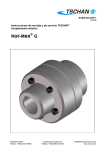
Barrel Coupling
R
BAWG007-GBR-0
Assembly and Service Manual
1
INITIAL CONSIDERATIONS
-The TSCHAN barrel coupling is supplied as a whole unit, ready to be mounted, but not provided with lubricant. Therefore, before it
is put into service it must be lubricated in the required quantity with the appropriate lubricant, as indicated in chapter 4, table 3.
- In case it is necessary to dismantle the coupling (i.e. for the machining of a pilot bored hub or for the shrink fit setting-up) it is very
important to make sure that when assembling it again the hub and the sleeve-flange pair off without taking place a possible mixture
between different unities and it will also have to be done in the same relative position at is was supplied. This is achieved by
making coincide the marked tooth of the hub with the corresponding marked tooth of the sleeve-flange ( reference fig. 1 and 2).
- The bearing-support of the drum at the opposite side of the coupling must absorb the axial forces generated during the service
and must convey them to the structure. The axial component of any structural distortion must not exceed the maximum acceptable
axial displacement for the coupling indicated on table no. 1.
- Fixing screws for the assembly of the coupling to the drum and the securing of covers, must have a minimum 8.8 quality. The
tightening torque of these screws will have to be in accordance with the said quality and also- with the material of the covers and
of the drum flange. See values on table no. 2.
1.
2.
3.
4.
5.
6.
7.
8.
9.
10.
11.
12.
13.
14.
15.
16.
Hub
Sleeve flange
Barrel
External cover
Pointer
Internal cover
Seal
Retaining ring
Carrier face
Wear marks
Axial adjustment mark
Assembly mark
Lubricant filler
Overflow hole
Extractor hole
Fixing screw
fig. 1
Size
± mm
25
3
50
3
75
4
100
4
130
4
160
4
Max. axial displacement
200
300
400
600
4
4
4
6
1000
6
1500
6
2600
6
3400
8
4200
8
6200
8
Table no. 1
Screw quality 8.8
Torque [Nm]
Tightening torque
M8
M10
M12
26
50
90
M16
215
M20
420
M24
725
Table no. 2
TK-gb-05-00.doc
Tschan GmbH
Zweibrücker Straße 104
- page 1 of 4 D-66538 Neunkirchen / Saar
Postfach 2166
D-66521 Neunkirchen / Saar
2
SETTING UP ON THE REDUCER SHAFT
HUB-SHAFT CONNECTIONS BY MEANS OF KEYS; SPLINES; ETC:
-Clean the surfaces of the hub-bore and the shaft.
-Pre-heat the whole coupling by putting it into a bath of hot oil at a temperature which does not exceed 80ºC so that the seals are
not damaged. The oil of bath must not attack those components manufactured on a nitrile base.
- Mount the hub on the shaft avoiding to bump it and applying force only to hub item 1.
- Check the free axial displacement of the sleeve-flange.
HUB-SHAFT CONNECTION BY MEANS OF INTERFERENCE WITHOUT KEYS
In this case it is necessary to separate the hub from the rest of the coupling.
- Unfasten and take away the external cover as well as the sleeve-flange, the external retainer ring and the barrels.
- Clean the surfaces of the hub and the shaft.
- Place the external cover together with its joint and the retainer ring over the shaft. Make sure that the space between the cover
and the reducer is sufficient to house the fixing screws. If it was not so, the screws have to be previously housed in the cover.
- Heat the hub up to the appropriate temperature for its mounting. Whatever method of heating is used, it must be progressive along
the whole surface, preventing any localized heating spots. As an indication, a maximum temperature of 200ºC is usually enough
for this operation.
- Mount the hub on the shaft until reaching a reference-mark previously set or until the hub face matches the shaft end. At this
stage it is crucial to avoid any contact of the hot hub with the seal. Before continuing with the procedure, wait until the hub cools
down and reaches room temperature.
- Set-up the sleeve-flange over the hub, checking that the matching and the position reference of these ones is the correct one.
(fig. 2).
- House the barrels in their cavities and place the external retainer ring in its channel.
- Fix the external cover making the pointer coincide with the marks over the hub.
- Check the free axial displacement of the sleeve-flange.
fig. 2
TK-gb-05-00.doc
Tschan GmbH
Zweibrücker Straße 104
- page 2 of 4 D-66538 Neunkirchen / Saar
Postfach 2166
D-66521 Neunkirchen / Saar
3
AXIAL ADJUSTEMENT AND ALIGNMENT
Once the coupling has been fixed to the drum flange, its correct axial position is indicated by the coincidence of the mark at the
pointer with the mark of the hub (fig. 3). At the position the setting of the opposite bearing support of the drum to the base is
defined.
Afterwards, the angle alignment is checked by measuring the gap „X“, (fig. 4) at four points with a separation of 90º by using a
reference ruler. As an indication, the following maximum difference between the 4 measurements to the height of the external part
of the sleeve-flange can be considered as acceptable:
0.3 mm for sizes ≤ TK-600
0.6 mm for sizes ≥ TK-1000
fig. 3
4
fig. 4
LUBRICATION
Once the setting-up has been done and before the putting into service, the internal chamber has to be filled with lubricant EP2
(Extreme Pressure additive and consistency NLGI=2). The inlet at the external cover is suitable for placing a tubular extension up to
the external part of the drum, making access easier. In practice, lubricant must be fed until it comes out of the oil overflow hole at
the opposite part of the hub. As an indication, Table no. 3 shows the approximate amount depending on the different sizes.
Table no. 4 shows certain references of appropriate lubricants for temperatures of -20 and up to 80°C. Please ask for advice if
temperatures are out of that range.
Size
kg
25
0.08
50
0.10
75
0.12
100
0.14
130
0.15
160
0.17
200
0.19
300
0.23
400
0.45
600
0.57
1000
0.65
1500
0.72
2600
0.9
3400
1.0
4200
1.3
6200
2.0
Table no. 3
Reference
CENTOPLEX 2 EP
VERKOL EP -2
AGUILA Nr 850 EP-2
BP Energrease LS-EP 2
SHELL alvania EP-2
MOBILUX EP2
BEACON EP2
Greases (-20 °C - +80°C)
Producer
KLÜBER LUBRICATION
VERKOL, S.A.
BRUGAROLAS
BP
SHELL
MOBIL
ESSO
Table no. 4
TK-gb-05-00.doc
Tschan GmbH
Zweibrücker Straße 104
- page 3 of 4 D-66538 Neunkirchen / Saar
Postfach 2166
D-66521 Neunkirchen / Saar
5
MAINTENANCE
LUBRICATION PERIODICITY
Depending on the operating conditions the lubricant must be completly renewed every 2000 up to 3000 hours of operation and as a
minimum, once a year.
For ist renewal, feed the lubricant through the inlet, ejecting the used lubricant through the overflow hole. When new lubricant
starts being ejected out of this overflow hole it will mean that the operation has been completed.
PERIODICAL INSPECTIONS
At least once a year the following checkings must be carried out:
- Tightening of all the screws up to the recommend values and replacement of the damaged ones.
- Internal wear of the teeth. The position of the mark over the pointer in relation to the marks over the hub, (fig. 5), will be an
indicator of the state of the flanks wear. When the equipment is new, the pointer mark is centered (case a). When it reaches the
limit (case b) the whole coupling has to be replaced.
Table no. 5 shows the maximum permissible wear values, „m/2“, for applications which imply one only sense of loading (typical
case of the hoisting in cranes). With applications of reversible loading sense, the amplitude between the marks must be divided by
2. Unless it is expressly asked for, couplings are standardly supplied with the marks according to the aforementioned table and
therefore, it is advisable to modify them, if the application requires so, in order to correctly asses the wear evolution.
- Axial adjustement According to fig. 2. If deviation was close to the maximum acceptable value on table no. 1, the seat position
of the support bearing must be readjusted.
- Seals control. If any deterioration appears on the sealing lips, these must be replaced.
fig. 5a
Between marks O.K.
Size
„m/2“ [mm]
25
4
50
4
fig. 5b
Wear limit
75
4
Wear control
100 130 160 200 300 400 600 1000 1500
4
6
6
6
6
6
8
8
8
2600
8
3400 4200
8
8
6200
8
Table no. 5
TK-gb-05-00.doc
Tschan GmbH
Zweibrücker Straße 104
- page 4 of 4 D-66538 Neunkirchen / Saar
Postfach 2166
D-66521 Neunkirchen / Saar


![manual de instrucciones y ce nº serie 42[...]](http://vs1.manualzilla.com/store/data/006245767_1-c7f58b57d1ee3562d103ef3dc5a749e8-150x150.png)