1
TECHNICAL & SERVICE MANUAL
ADR518CW
AE518SC
AE518SC3 / AER518SCL3
ADR518HW
AE518SH
AE518SH3 / AER518SH3
®
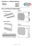
SPLIT SYSTEM AIR CONDITIONER
INDOOR UNIT
OUTDOOR UNIT
0.8180.224.0
OCTOBER 01
TABLE OF CONTENTS
A
SPECIFICATIONS...........................................................................................................PAGE...3
B
MAJOR COMPONENT SPECIFICATION.....................................................................................9
C
OTHERS COMPONENT SPECIFICATIONS................................................................................16
D
OPERATING RANGE....................................................................................................................21
E
DIMENSIONALE DATA.................................................................................................................22
F
FUNCTION.....................................................................................................................................24
G
REFRIGERANT FLOW DIAGRAM................................................................................................31
H
ELECTRIC WIRING DIAGRAM.....................................................................................................32
I
TROUBLESHOOTING COOLING MODEL...................................................................................36
L
SAME PARTS OF AIR CONDITIONER DO NOT OPERATE........................................................43
M
AIR CONDITIONER OPERATES,BUT ABNORMALITIES OCCUR.............................................44
N
TROUBLESHOOTING HEATING MODEL....................................................................................45
O
SAME PARTS OF AIR CONDITIONER DO NOT OPERATE.......................................................52
P
AIR CONDITIONER OPERATES,BUT ABNORMALITIES OCCUR............................................55
Q
IS SENSOR IS DEFECTIVE..........................................................................................................56
R
CHECKING ELECTRICAL ...........................................................................................................59
H
A
SPECIFICATIONS
1) UNIT SPECIFICATIONS
UNIT MODEL
INDOOR UNIT
OUTDOOR UNIT
ADR518CW
AE518SC
Power source
220 / 230 / 240V - 1 - 50 Hz
PERFORMANCES
COOLING
BTU/h
Capacity
16,900
W (Kcal/h)
Air circulation (high - med - low)
4.950 (4,250)
m3/h
780
External static pressure (high speed) mm w.g. (Pa)
Moisture removal (high speed)
l/h
ELECTRICAL
Umidità asportataRATINGS
(alta velocità)
5 (49) at shipment - 10 (98) using the Booster cable
2,8
l/h
0,9
Voltage rating
V
230
Available voltage range
V
198 ÷ 264
Running ampere
A
9.5
Power input
W
2,06
Power factor
%
94
Compressor locked rotor amperes
A
46
W/W
2.4
C.O.P.
FEATURES
Controls
Microprocessor
Control unit
Remote control
Temperature control
I.C. thermostat
Timer
ON/OFF 12 hours
Fan speed indoor / outdoor
3 + auto / 2 auto
Air filter
Washable, easy access (accessory)
Compressor
Rotary (hermetic)
Refrigerant / ref. control / amount charged at ship g
Operation sound
Outdoor Hi / Lo
Max. tubing length
42 / 37 / 32
Max. allowable tubing length
Limit of elevation difference
between the two units
51 / 44
(3 m) dB-A
m
Required amount of additional refrigerant
Refrigerant tube
diameter
R22 / capillary tube / 1.710 g
Indoor Hi / Me / Lo (1 m) dB-A
(with factory R22 charge)
10
m ....(with.R22.addition)....................20
g/m
25
m
7
Narrow tube
mm (in.)
6.35 (1/4”)
Wide tube
mm (in.)
12.7 (1/2”)
Accessory
Booster cable
DIMENSIONS AND WEIGTH
INDOOR UNIT
OUTDOOR UNIT
Higth
mm
316
630
Width
mm
750
830
Depth
mm
665
305
Net weigth
kg
42
52
Shipping volume
m3
0,33
0,3
Shipping weight (approx.)
kg
44
57
Data subject to change without notice.
NOTA. Rating conditions:
Cooling: Outside air temp.: 35°C DB, indoor unit entering air temp.: 27°C DB / 19°C WB
3
UNIT MODEL
INDOOR UNIT
OUTDOOR UNIT
ADR518CW
AE518SC3
Power source
400V - 3N - 50 Hz (4 wires)
PERFORMANCES
COOLING
BTU/h
Capacity
16,900
W (Kcal/h)
Air circulation (high - med - low)
4.950 (4250)
m3/h
780
External static pressure (high speed) mm w.g. (Pa)
Moisture removal (high speed)
l/h
ELECTRICAL
Umidità asportataRATINGS
(alta velocità)
5 (49) at shipment - 10 (98) using the Booster cable
2,8
l/h
0,9
Voltage rating
V
400
Available voltage range
V
342 ÷ 440
Running ampere
A
4.0
Power input
W
1.96
Power factor
%
84
Compressor locked rotor amperes
A
21.5
C.O.P.
W/W
2.5
FEATURES
Controls
Microprocessor
Control unit
Remote control
Temperature control
I.C. thermostat
Timer
ON/OFF 12 hours
Fan speed indoor / outdoor
3 + auto / 2 auto
Air filter
Washable, easy access (accessory)
Compressor
Rotary (hermetic)
Refrigerant / ref. control / amount charged at ship g
Operation sound
Outdoor Hi / Lo
Max. tubing length
42 / 37 / 32
Required amount of additional refrigerant
Limit of elevation difference
between the two units
51 / 44
(3 m) dB-A
m
Max. allowable tubing length
Refrigerant tube
diameter
R22 / capillary tube / 1.405 g
Indoor Hi / Me / Lo (1 m) dB-A
(with factory R22 charge)
10
m ....(with.R22.addition).....................20
g/m
25
7
m
Narrow tube
mm (in.)
6,35 (1/4”)
Wide tube
mm (in.)
12,7 (1/2”)
Accessory
Booster cable
DIMENSIONS AND WEIGTH
INDOOR UNIT
OUTDOOR UNIT
Higth
mm
316
630
Width
mm
750
830
Depth
mm
665
305
Net weigth
kg
42
52
Shipping volume
m3
0,33
0,3
Shipping weight (approx.)
kg
44
57
Data subject to change without notice.
NOTA. Rating conditions:
Cooling: Outside air temp.: 35°C DB, indoor unit entering air temp.: 27°C DB / 19°C WB
4
UNIT MODEL
INDOOR UNIT
OUTDOOR UNIT
ADR518CW
AER518SCL3
Power source
400V - 3N - 50 Hz (4 wires)
PERFORMANCES
COOLING
BTU/h
Capacity
17.400
W (Kcal/h)
Air circulation (high - med - low)
5900 (5070)
m3/h
780
External static pressure (high speed) mm w.g. (Pa)
5 (49 at shipment - 10 (98) using the Booster cable
Moisture removal (high speed)
l/h
2.8
ELECTRICAL
Umidità asportataRATINGS
(alta velocità)
l/h
0,9
Voltage rating
V
400
Available voltage range
V
342 : 440
Running ampere
A
3.6
Power input
W
2.000
Power factor
%
80
Compressor locked rotor amperes
A
21.5
C.O.P.
W/W
2,3
FEATURES
Controls
Microprocessor
Control unit
Remote control
Temperature control
I.C. thermostat
Timer
ON/OFF 12 hours
Fan speed indoor / outdoor
3 + auto / 2 auto
Air filter
Washable, easy access (accessory)
Compressor
Rotary (hermetic)
Refrigerant / ref. control / amount charged at ship g
Operation sound
Outdoor Hi / Lo
Max. tubing length
42 / 37 / 32
Required amount of additional refrigerant
Limit of elevation difference
between the two units
51/ 44
(3 m) dB-A
m
Max. allowable tubing length
Refrigerant tube
diameter
R407C / capillary tube / 1.710 g
Indoor Hi / Me / Lo (1 m) dB-A
m
(with factory R407C charge)
10
(with R407C addition)
g/m
30
25
7
m
Narrow tube
mm (in.)
6,35 (1/4”)
Wide tube
mm (in.)
12.7(1/2")
Accessory
Booster cable
DIMENSIONS AND WEIGTH
INDOOR UNIT
OUTDOOR UNIT
mm
316
630
Width
mm
750
830
Depth
mm
665
305
Higth
Net weigth
kg
42
52
Shipping volume
m3
0.33
0.3
Shipping weight (approx.)
kg
44
57
Data subject to change without notice.
NOTA. Rating conditions:
Cooling: Outside air temp.: 35°C DB, indoor unit entering air temp.: 27°C DB / 19°C WB
5
INDOOR UNIT
OUTDOOR UNIT
UNIT MODEL
ADR518HW
AE518SH
Power source
220 / 230 / 240V - 1 - 50 Hz
PERFORMANCES
COOLING
BTU/h
Capacity
W (Kcal/h)
Air circulation (high - med - low)
HEATING
16.900
20500
4.950 (4.257)
6000(5160)
m3/h
750
External static pressure (high speed) mm w.g. (Pa)
Moisture removal (high speed)
l/h
ELECTRICAL
Umidità asportataRATINGS
(alta velocità)
5 (49) at shipment - 10 (98) using the Booster cable
2.8
---
l/h
0,9
Voltage rating
V
230
Available voltage range
V
Running ampere
A
9.8
Power input
W
2.100
Power factor
%
93
Compressor locked rotor amperes
A
C.O.P.
198 ÷ 264
10.3
2.150
90
57
W/W
2.35
2.8
FEATURES
Controls
Microprocessor
Control unit
Remote control
Temperature control
I.C. thermostat
Timer
ON/OFF 12 hours
Fan speed indoor / outdoor
3 + auto / 2 auto
Air filter
Washable, easy access (accessory)
Compressor
Rotary (hermetic)
Refrigerant / ref. control / amount charged at ship g
R22 / capillary tube / 1.87 g
42 / 37 / 32
Indoor Hi / Me / Lo (1 m) dB-A
Operation sound
Outdoor Hi / Lo
Max. tubing length
m
Max. allowable tubing length
Required amount of additional refrigerant
Limit of elevation difference
between the two units
Refrigerant tube
diameter
51 / 44
(3 m) dB-A
(standard refrigerant charge)
10
m ....(with.R22.addition).....................30
g/m
25
7
m
Narrow tube
mm (in.)
6,35 (1/4”)
Wide tube
mm (in.)
12.7 (1/2”)
Accessory
Booster cable
DIMENSIONS AND WEIGTH
Higth
mm
Width
mm
Depth
mm
INDOOR UNIT
OUTDOOR UNIT
316
630
750
665
830
305
Net weigth
kg
42
52
Shipping volume
m3
0,33
0.3
Shipping weight (approx.)
kg
44
57
Data subject to change without notice.
NOTA. Rating conditions:
Cooling:
Outside air temp.: 35°C DB, indoor unit entering air temp.: 27°C DB / 19°C WB
6
INDOOR UNIT
OUTDOOR UNIT
UNIT MODEL
ADR518HW
AE518SH3
Power source
400V - 3N - 50 Hz (4 wires)
PERFORMANCES
COOLING
BTU/h
Capacity
W (Kcal/h)
Air circulation (high - med - low)
HEATING
16.100
19.800
4.700 (4.042)
5.800(6.744)
m3/h
750
External static pressure (high speed) mm w.g. (Pa)
Moisture removal (high speed)
l/h
ELECTRICAL
Umidità asportataRATINGS
(alta velocità)
5 (49) at shipment - 10 (98) using the Booster cable
2.8
---
l/h
0,9
Voltage rating
V
400
Available voltage range
V
Running ampere
A
3.8
Power input
W
2.000
Power factor
%
93
Compressor locked rotor amperes
A
C.O.P.
342 ÷ 440
4.0
2.100
90
22
W/W
2.35
2.76
FEATURES
Controls
Microprocessor
Control unit
Remote control
Temperature control
I.C. thermostat
Timer
ON/OFF 12 hours
Fan speed indoor / outdoor
3 + auto / 2 auto
Air filter
Washable, easy access (accessory)
Compressor
Rotary (hermetic)
Refrigerant / ref. control / amount charged at ship g
R22 / capillary tube / 2.450g
42 / 37 / 32
Indoor Hi / Me / Lo (1 m) dB-A
Operation sound
Outdoor Hi / Lo
Max. tubing length
m
Max. allowable tubing length
Required amount of additional refrigerant
Limit of elevation difference
between the two units
Refrigerant tube
diameter
51 / 44
(3 m) dB-A
(standard refrigerant charge)
10
m ....(with.R22.addition).....................30
g/m
25
7
m
Narrow tube
mm (in.)
6,35 (1/4”)
Wide tube
mm (in.)
12.7 (1/2”)
Accessory
Booster cable
DIMENSIONS AND WEIGTH
INDOOR UNIT
OUTDOOR UNIT
mm
316
630
Width
mm
750
830
Depth
mm
665
305
Higth
Net weigth
kg
42
52
Shipping volume
m3
0,33
0.3
Shipping weight (approx.)
kg
44
57
Data subject to change without notice.
NOTA. Rating conditions:
Cooling:
Outside air temp.: 35°C DB, indoor unit entering air temp.: 27°C DB / 19°C WB
7
INDOOR UNIT
OUTDOOR UNIT
UNIT MODEL
ADR518HW
AER518SH3
Power source
400V - 3N - 50 Hz (4 wires)
PERFORMANCES
COOLING
BTU/h
Capacity
W (Kcal/h)
Air circulation (high - med - low)
HEATING
16.400
21.500
4.800 (4.128)
6300(5418)
m3/h
750
External static pressure (high speed) mm w.g. (Pa)
Moisture removal (high speed)
l/h
ELECTRICAL
Umidità asportataRATINGS
(alta velocità)
5 (49) at shipment - 10 (98) using the Booster cable
2.8
---
l/h
0,9
Voltage rating
V
400
Available voltage range
V
Running ampere
A
4.0
Power input
W
2.150
Power factor
%
93
Compressor locked rotor amperes
A
C.O.P.
342 ÷ 440
4.2
2.250
90
22
W/W
2.23
2.8
FEATURES
Controls
Microprocessor
Control unit
Remote control
Temperature control
I.C. thermostat
Timer
ON/OFF 12 hours
Fan speed indoor / outdoor
3 + auto / 2 auto
Air filter
Washable, easy access (accessory)
Compressor
Rotary (hermetic)
Refrigerant / ref. control / amount charged at ship g
R407C / capillary tube / 1.600 g
42 / 37 / 32
Indoor Hi / Me / Lo (1 m) dB-A
Operation sound
Outdoor Hi / Lo
Max. tubing length
m
Max. allowable tubing length
Required amount of additional refrigerant
Limit of elevation difference
between the two units
Refrigerant tube
diameter
51 / 44
(3 m) dB-A
(standard refrigerant charge)
10
m ....(with.R407C.addition)................30
g/m
25
7
m
Narrow tube
mm (in.)
6,35 (1/4”)
Wide tube
mm (in.)
12.7 (1/2”)
Accessory
Booster cable
DIMENSIONS AND WEIGTH
Higth
mm
INDOOR UNIT
OUTDOOR UNIT
316
630
Width
mm
750
830
Depth
mm
665
305
Net weigth
kg
42
52
Shipping volume
m3
0,33
0.3
Shipping weight (approx.)
kg
44
57
Data subject to change without notice.
NOTA. Rating conditions:
Cooling:
Outside air temp.: 35°C DB, indoor unit entering air temp.: 27°C DB / 19°C WB
8
B
MAJOR COMPONENT SPECIFICATIONS
INDOOR UNIT
UNIT MODEL
ADR518CW / ADR518HW
Power source
220 / 230 / 240V -1 - 50 Hz
REMOTE CONTROL UNIT
CONTROLLER P.C.B.
POW-U186GH
Controls
Microprocessor
RCS-U251G
Control circuit fuse
250V - 3A
FAN
Centrifugal
Number ... dia. / length
mm
2 ... Ø 200 / L 230
FAN MOTOR
Model ... Number
K48410M01526 ... 1
Power source
V
220 / 230 / 240-1-50 Hz
No. di poli ... giri/min (230V-max)
4 ... 1040
Nominal output
W
Coil resistance
(Ambient temp. 20°C)
Ω
70
WHT - BRN : 181,1
ORG - VLT : 136,8
YEL - ORG : 151,4
BLK - YEL : 120,6
WHT - VLT : 112,7
VLT - PNK : 144,2
Internal type
130 ± 18
SAFETY DEVICES
Operating temp.
Open
°C
Close
°C
179 ± 15
µF
Run capacitor
5
VAC
440
DRAIN PUMP
Model
Rated
PC
Voltage
AC 230V - 50 Hz
Input
114.7 W
Total head capacity
0.4 m / 0.6 l/m
HEAT EXCHANGER
Coil
Aluminum plate fin / Copper tube
Rows
Fin pitch
Fase area
3
mm
1,8
0,125
m2
EXTERNAL FINISH
Insulated galvanized metal sheet
9
Outdoor Unit
Controller
PCB
AE518SC3
Part No.
POW-C181BL
Control circuit fuse
250V – 5A
Type
Rotary (Hermetic)
Compressor model
C-2R173H8V- 80817C88D
380 – 400 V – 3N ~ 50 Hz
Source
Nominal output
W
Compressor oil ... Amount
cc
Coil resistance (Ambient temp. 25°C)
Ω
1,700
SUNISO 4GSD-T ... 800
C – R : 6.369
Compressor
C – S : 6.073
R – S : 6.217
Type
Safety
devices
Overload relay
Operating temp.
Open
°C
Close
°C
HOE-10TB TH-5A
125 ± 5
—
—
—
5A
µF
Run capacitor
—
VAC
—
Crank case heater
240V 30W
Type
Propeller
Q´ty ... Dia.
mm
1 ... ø400
Fan motor model ... Q´ty
SMEN 19 TFB6055 ... 1
220 – 230 V ~ 50 Hz
Source
No. of poles ... rpm (220 V, High)
Fan & Fan Motor
External protector
—
Automatic reclosing
Operating amp.(Ambient temp. 25°C)
6 ... 910
Nominal output
W
Coil resistance (Ambient temp. 20°C)
Ω
43
WHT – BRN : 77.7
WHT - YEL : 366
WHT – PNK : 211
Safety
devices
Type
Operating temp.
Run capacitor
Heat
Exch. Coil
Internal protector
Internal type
Open
°C
130 ± 5
Close
Automatic reclosing
µF
2.0
VAC
400
Coil
Aluminum plate fin / Copper tube
Rows
Fin pitch
Face area
2
mm
1.8
m2
0.508
External Finish
Acrylic baked-on enamel finish
DATA SUBJECT TO CHANGE WITHOUT NOTICE.
10
Outdoor Unit
AE518SC
Controller PCB
—
Type
Rotary (Hermetic)
Compressor
Compressor model
PH36VTRT
Nominal output
W
1,600
Compressor oil ... Amount
cc
DIAMOND... 900
Coil resistance (Ambient temp. 20°C)
Ω
C – R : 1.06
C – S : 2.03
Type
Safety
devices
Internal protector (OLR)
Overload relay
Operating temp.
—
Open
°C
Automatic opening 155 ± 5
Close
°C
Automatic reclosing 90 ± 10
Operating amp. (Ambient temp. 25 C)
Run capacitor
Trip in 3 to 10 sec at 54A
µF
55.0
VAC
450
Crank case heater
—
Type
Propeller
Number ... Dia.
mm
1 ... ø 400
Fan motor model ... Number
Smen 19TFB6055 ... 1
Fan & Fan Motor
No. of poles ... rpm (230 V, High)
6 ... 910
Nominal output
W
Coil resistance (Ambient temp. 20°C)
Ω
43
WHT – BRN : 77.7 ± 7%
WHT – YEL : 366.0 ± 7%
WHT – PNK : 211.0 ± 7%
Safety
devices
Type
Operating temp.
Thermal protector
Open
°C
130 ± 5
Close
Heat
Exch. Coil
Run capacitor
Automatic reclosing
µF
2.0
VAC
440
Coil
Aluminum plate fin / Copper tube
Rows
Fin pitch
Face area
2
mm
1.8
m2
0.508
External Finish
Acrylic baked-on enamel finish
DATA SUBJECT TO CHANGE WITHOUT NOTICE.
11
Outdoor Unit
Controller
PCB
AER518SCL3
Part No.
POW-C181BL
Control circuit fuse
250V – 5A
Type
Rotary (Hermetic)
Compressor model
C-2RN173H8W 80807088
380 – 400 V – 3N ~ 50 Hz
Source
Nominal output
W
1,700
Compressor oil ... Amount
cc
FV68S ... 800
Coil resistance (Ambient temp. 25°C)
Ω
C – R : 6.369
Compressor
C – S : 6.073
R – S : 6.217
Type
Safety
devices
Overload relay
Operating temp.
HOE-10TB TH-5A
°C
Automatic opening
—
Close
°C
Automatic reclosing
—
—
µF
Run capacitor
5A
—
VAC
—
Crank case heater
240V 30W
Type
Propeller
Q´ty ... Dia.
mm
1 ... ø400
Fan motor model ... Q´ty
SMEN 19 TFB6047 ... 1
220 – 230 V ~ 50 Hz
Source
No. of poles ... rpm (220 V, High)
Fan & Fan Motor
External protector
—
Open
Operating amp.(Ambient temp. 25°C)
6 ... 910
Nominal output
W
Coil resistance (Ambient temp. 20°C)
Ω
43
WHT – BRN : 83.4
WHT – PNK : 218.7
Safety
devices
Type
Operating temp.
Run capacitor
Heat
Exch. Coil
Internal protector
Internal type
Open
°C
130 ± 5
Close
Automatic reclosing
µF
2.0
VAC
440
Coil
Aluminum plate fin / Copper tube
Rows
Fin pitch
Face area
2
mm
1.8
m2
0.508
External Finish
Acrylic baked-on enamel finish
DATA SUBJECT TO CHANGE WITHOUT NOTICE.
12
Outdoor Unit
AE518SH
Controller PCB
POW – C186GH
Type
Rotary (Hermetic)
Compressor
Compressor model
SCI PH36VTRT
Nominal output
W
Compressor oil ... Amount
cc
Coil resistance (Ambient temp. 20°C)
Ω
1600
DIAMOND....900
C – R : 1.06
C – S : 2.03
Type
Safety
devices
Internal protector
Overload relay
Operating temp.
MRA-8967-9200
Open
°C
Close
°C
160 ± 5
84± 11
Operating amp.(Ambient temp. 25°C)
Run capacitor
Trip in 6 to 16 sec. at 55 A
µF
55.0
VAC
450
Crank case heater
240V 30W
Type
Propeller
Number ... Dia.
mm
1 ... ø 400
Fan motor model ... Number
Smen 19TFB6055 ... 1
Fan & Fan Motor
No. of poles ... rpm (230 V, High)
6 ... 900
Nominal output
W
Coil resistance (Ambient temp. 20°C)
Ω
50
WHT – BRN : 77.7 ± 7%
WHT – YEL : 366.0 ± 7%
WHT – PNK : 211 ± 7%
Safety
devices
Type
Operating temp.
Internal protector
Open
°C
130 ±8
Close
Run capacitor
Heat
Exch. Coil
External (OLR)
Automatic reclosing
µF
2.0
VAC
440
Coil
Aluminum plate fin / Copper tube
Rows
Fin pitch
Face area
2
mm
1.6
m2
0.453
External Finish
Acrylic baked-on enamel finish
DATA SUBJECT TO CHANGE WITHOUT NOTICE.
13
Outdoor Unit
AE518SH3
380 - 400 V - 3N ~ 50 Hz
220 - 240 V ~ 50 Hz
POW-C186GH
Power source
Control circuit
CONTROLLER PCB
COMPRESSOR
Type
Compressor model
Source
Nominal output
Compressor oil ... Amount
C-R
C-S
R-S
Coil resistance (Ambient temp. 25°C)
Safety devices:
Type
Overload relay
Open
Close
Operating amp. (Ambient temp. 25°C)
Operating temp.
°C
°C
µF
VAC
Run capacitor
Crank case heater
FAN AND FAN MOTOR
Type
Number ... Dia.
Fan motor model ... Number
Source
No. of poles ... rpm (220 V)
Nominal output
Coil resistance (Ambient temp. 20°C)
Safety devices:
W
cc
Ω
Ω
Ω
mm
WHT - BRN
WHT - YEL
WHT - PNK
Type
Operating temp.
Open
Close
W
Ω
Ω
Ω
°C
µF
VAC
Run capacitor
HEAT EXCH. COIL
Coil
Rows
Fin pitch
Face area
EXTERNAL FINISH
mm
m2
Rotary (Hermetic)
C-R173H8M-806-389-88
380 - 400 V - 3N ~ 50 Hz
1700
SUNISO4CS ... 800
5,62
5,51
5,62
Internal protector
External protector
//
HOE-10TB TH-7A
120 ± 5
//
Automatic reclosing
//
//
5A
//
//
240 V - 30 W
Propeller
1 ... Ø400
Smen 19TFB6055 ... 1
220 - 240 V ~ 50 Hz
6 ... 900
50
77,7
366,0
211,0
Internal protector
130 ± 8
Automatic reclosing
2
440
Aluminum plate fin / Copper tube
2
1,6
0,453
Acrylic baked-on enamel finish
Data subject to change without notice.
14
Outdoor Unit
AER518SH3
380 - 400 V - 3N ~ 50 Hz
220 - 240 V ~ 50 Hz
POW-C186GH
Power source
Control circuit
CONTROLLER PCB
COMPRESSOR
Type
Compressor model
Source
Nominal output
Compressor oil ... Amount
C-R
C-S
R-S
Coil resistance (Ambient temp. 25°C)
Safety devices:
Type
Overload relay
Open
Close
Operating amp. (Ambient temp. 25°C)
Operating temp.
°C
°C
µF
VAC
Run capacitor
Crank case heater
FAN AND FAN MOTOR
Type
Number ... Dia.
Fan motor model ... Number
Source
No. of poles ... rpm (220 V)
Nominal output
Coil resistance (Ambient temp. 20°C)
Safety devices:
W
cc
Ω
Ω
Ω
mm
WHT - BRN
WHT - YEL
WHT - PNK
Type
Operating temp.
Open
Close
W
Ω
Ω
Ω
°C
µF
VAC
Run capacitor
HEAT EXCH. COIL
Coil
Rows
Fin pitch
Face area
EXTERNAL FINISH
mm
m2
Rotary (Hermetic)
C-2RN173H8A 80242088
380 - 400 V - 3N ~ 50 Hz
1700
FV68S ... 800
5,62
5,51
5,62
Internal protector
External protector
//
HOE-10TB TH-7A
120 ± 5
//
Automatic reclosing
//
//
5A
//
//
240 V - 30 W
Propeller
1 ... Ø400
Smen 19TFB6055 ... 1
220 - 240 V ~ 50 Hz
6 ... 900
50
77,7
366,0
211,0
Internal protector
130 ± 8
Automatic reclosing
2
440
Aluminum plate fin / Copper tube
2
1,6
0,453
Acrylic baked-on enamel finish
Data subject to change without notice.
15
C
OTHER COMPONENT SPECIFICATIONS
Outdoor Unit
AE518SC
Power Relay
G7L-2A-TUB
Coil rating
AC 200 – 240V, 50/60Hz
Coil resistance
kΩ (at 23°C)
( 21 ± 15% )
Contact rating
AC 220V, 25A
Thermostat (Fan Speed Control 23S)
Switching temp.
MQT5S-27YZJ
°C
Contact rating
Outdoor Unit
high ➞ LOW
+0
23.5°C –2.5
low ➞ HIGH
27.0°C +0
–3
AC 220V, 3A
AE518SC3
Negative Phase Relay (47C)
RDR-S400
Rating
AC 415V, 3-phase 50Hz
Contact rating
AC 400V, 1A
Operation
Positive phase: ON
Negative phase: OFF
Electro Magnetic Contactor (MG)
HOE-10TB TH-5A
Magnetic contactor
Coil rating
Coil resistance
AC 220–240V, 50Hz / AC 240–260V, 60Hz
Ω (at 25°C)
1,260 ± 10%
Contact rating (Main)
AC 440V, 8A
Thermal relay (Overcurrent relay)
MQT5S-27YZJ
5A
Operating amperes
16
Outdoor Unit
AER518SCL3
Thermistor (Coil sensor TH3 / Air sensor TH4)
Resistance
PBC-41E-S4 / PBC-41E-S8
kΩ
–20°C 40.1 ± 5%
–10°C 24.4 ± 5%
30°C 4.4 ± 5%
0°C 15.3 ± 5%
40°C 3.0 ± 5%
10°C
Solid State Relay (SSR)
20°C 6.5 ± 5%
9.9 ± 5%
50°C 2.1 ± 5%
G3L-205TL-TS1
Input
Rated voltage
DC 12V
Control voltage range
DC 0V to 6.4V
Load voltage range
AC 75V to 264V, 50Hz
Negative Phase Relay (47C)
RDR-S400
Rating
AC 415V, 3-phase 50Hz
Contact rating
AC 400V, 1A
Operation
Positive phase: ON
Negative phase: OFF
Electro Magnetic Contactor (MG)
HOE-10TB TH-5A
Magnetic contactor
Coil rating
Coil resistance
AC 220–240V, 50Hz / AC 240–260V, 60Hz
Ω (at 25°C)
1,260 ± 10%
Contact rating (Main)
AC 440V, 8A
Thermal relay (Overcurrent relay)
MQT5S-27YZJ
5A
Operating amperes
Transformer (TR2)
Rating
ATR-J105-I
Primary
AC 230V, 50Hz
Secondary
19V, 0.526A
Capacity
Coil resistance
10VA
Ω (at 22°C)
Thermal cut-off temp.
205 ± 10%
2.0 ± 10%
150°C
Power Relay
HH62S DC24V
Coil rating
Coil resistance
Primary (WHT – WHT):
Secondary (BRN – BRN):
DC 24V
kΩ (at 23°C)
650 ± 10%
Contact rating
AC 250V, 10A
17
Outdoor Unit
AE518SH
Power Relay (PR)
DFU24D1-F
Coil rating
Coil resistance
DC 24V
Ω (at 20°C)
650 ± 10%
Contact rating
AC 250V, 20A
Starting Relay (SR)
AMVL300A
Coil rating
Coil resistance
AC 300V, 50Hz
kΩ (at 23°C)
13.3 ± 2%
Contact rating
20A AC
Operating voltage
AC 185 – 217V, 50Hz
Return voltage
AC 60 – 120V, 50Hz
Thermostat (Defrost thermo. 23D)
Operating temp.
TRS02-12MSR
°C
Thermostat (Fan Speed Control 23S)
Switching temp.
Diff.
8 deg. below
high ➞ LOW
°C
23.5°C ±1.5
+0
low
➞ HIGH 50Hz,
27.0°C
AC 220-240V,
6W –3
Ω (at 20°C)
AC
220V,
3A
1.740
± 7%
4-way Valve (20S)
LB64012 (Coil), V26-110B (Valve)
Coil rating
Coil resistance
12 ± 2
MQT5S-27YZJ
Coil rating
Contact
rating
Coil resistance
ON
AC 220-240V, 50Hz, 6W
Ω (at 20°C)
1.740 ± 7%
Starting Capacitor
C4; C5
Capacitor
125 µF - 165V
Resistor
18KΩ - 2W
18
Outdoor Unit
AE518SH3
Electro Magnetic Contactor (MG)
HOE-10TB TH-5A
Magnetic contactor
Coil rating
Coil resistance
AC 220–240V, 50Hz / AC 240–260V, 60Hz
Ω (at 25°C)
1,260 ± 10%
Contact rating (Main)
AC 440V, 8A
Thermal relay (Overcurrent relay)
Operating amperes
5A
Negative Phase Relay (47C)
RDR-S400
Rating
AC 415V, 3-phase 50Hz
Contact rating
AC 400V, 1A
Operation
Positive phase: ON
Negative phase: OFF
Relay (PR)
MY2-TSDF
Coil rating
Coil resistance
DC 24V
Ω (at 20°C)
650 ± 10%
Contact rating
AC 200V, 5A
4-way Valve (SC)
LB64012 (Coil), V26-110B (Valve)
Coil rating
Coil resistance
AC 220/240V, 50Hz, 6W
Ω (at 20°C)
1,740 ± 7%
Thermostat (Defrost thermo. 23D)
Operating temp.
TRS02-12MSR
°C
Thermostat (Fan Speed Control 23S)
Switching temp.
ON
12 ± 2
Diff.
8 deg. below
MQT5S-27YZJ
°C
high → LOW
low → HIGH
Contact rating
23.5°C ± 1.5
27.0°C +0
–3
AC 220V, 3A
19
Outdoor Unit
AER518SH3
Electro Magnetic Contactor (MG)
HOE-10TB TH-5A
Magnetic contactor
Coil rating
Coil resistance
AC 220–240V, 50Hz / AC 240–260V, 60Hz
Ω (at 25°C)
1,260 ± 10%
Contact rating (Main)
AC 440V, 8A
Thermal relay (Overcurrent relay)
Operating amperes
5A
Negative Phase Relay (47C)
RDR-S400
Rating
AC 415V, 3-phase 50Hz
Contact rating
AC 400V, 1A
Operation
Positive phase: ON
Negative phase: OFF
Relay (PR)
MY2-TSDF
Coil rating
Coil resistance
DC 24V
Ω (at 20°C)
650 ± 10%
Contact rating
AC 200V, 5A
4-way Valve (SC)
LB64012 (Coil), V26-110B (Valve)
Coil rating
Coil resistance
AC 220/240V, 50Hz, 6W
Ω (at 20°C)
1,740 ± 7%
Thermostat (Defrost thermo. 23D)
Operating temp.
TRS02-12MSR
°C
Thermostat (Fan Speed Control 23S)
Switching temp.
ON
12 ± 2
Diff.
8 deg. below
MQT5S-27YZJ
°C
high → LOW
low → HIGH
Contact rating
23.5°C ± 1.5
27.0°C +0
–3
AC 220V, 3A
20
D
OPERATING RANGE
Function
Cooling
Temperature
INDOOR UNIT
OUTDOOR UNIT
Indoor air
intake temp.
Outdoor air
intake temp.
Maximum
35°C BS / 22.5°C BU
52°C BS
Minimum
19°C BS / 14°C BU,5
19°C BS
Referred to the systems - ADR518CW - AER518SCL3 only (3 phase and low ambient version)
Function
Cooling
INDOOR UNIT
OUTDOOR UNIT
Indoor air
intake temp.
Outdoor air
intake temp.
Maximum
35°C BS / 22°C BU
50°C BS
Minimum
19°C BS / 14°C BU,5
-15°C BS
Temperature
21
6
125
Dimension: mm
120
175
4 - ø3.1
(HOLE)
8
107
7
15
25
665
(HOLE)
150
310
150
220
480
220
35
210
195
(SUSPENSION BOLT PITCH)
830
280
150
32
150
750
35
46
(OVERALL DIM.)
74
46
29
120
256
42
32
20
5
26
4
(OVERALL
DIM.)
1
170
145
252
160
30
2
6
(HOLE)
2 - ø3.3
Refrigerant gas line (Wide tube - ø 12.70)
Drain connection (outside diam. 32)
Electrical junction box
Mounting for suspention
Duct connection for discharge (ø 200)
Duct connection for suction
Fresh air intake (ø 150)
3
4
5
6
7
8
Refrigerant liquid line (Narrow tube - ø 6.35)
LEGEND
30
120
3
38
310
20
2
1
60
REMOTE CONTROL UNIT
285
692
20
8 - ø3,1
5 - ø3,3
(HOLE
OPPOSITE SIDE)
590
38
13
107
(SUSPENSION BOLT
PITCH)
20
22
200
665
100
15
50
117
200
E
DIMENSIONAL DATA
Indoor unit ADR518SW
Outdoor Unit
538
146
337
307
Air intake
4 – ø12 holes
Air discharge
Wide tube service valve
ø12.7 (1/2")
Narrow tube service valve
ø6.35 (1/4")
305
19
95 61
630
830
Unit : mm
23
F
FUNCTION
1) ROOM TEMPERATURE CONTROL
Cooling
• Room temperature control is obtained by cycling the compressor ON and OFF under control of the room
temperature sensor in the remote control unit.
ROOM TEMPERATURE
MORE THAN
5 MINUTES
WITHIN
3 MINUTES
WITHIN
5 MINUTES
THERMO OFF
SET T + 0,5 ϒC
TEMPERATURE
T ϒC
THERMO
ON
THERMO
OFF
MORE THAN
5 MINUTES
MORE THAN
3 MINUTES
THERMO
ON
THERMO
OFF
3 MINUTES
5 MINUTES
COMPRESSOR
ON
OFF
ON
OFF
ON
OUTDOOR
FAN
ON
OFF
ON
OFF
ON
INDOOR
FAN
SET SPEED (MANUAL)
NOTA
• The control circuit will not attempt to turn the compressor ON until the compressor has been OFF for at
least 3 minutes.
To protect the compressor from stalling out when trying to start against the high side refrigerant pressure,
the control circuit has a built-in automatic time delay to allow the internal pressure to equalize.
• As a protective measure, the control circuit switches the compressor OFF after 5 minutes or more of
compressor operation.
• Thermo ON:
When the room temperature is above T + 1°C (T°C is set temperature).
Compressor ➔ ON.
• Thermo OFF: When the room temperature in equal to or below set temperature T°C.
Compressor ➔ OFF.
24
Heating
MORE THAN
5 MINUTES
THERMO
OFF
THERMO
ON
THERMO
OFF
SET TEMP. T°C
T-0.5°C
ROOM TEMP.
5 MINUTES
5 MINUTES
OFF
ON
OFF
ON
OFF
OUTDOOR
FAN
OFF
ON
OFF
ON
OFF
INDOOR
FAN
OFF
COMPRESSOR
30 SECONDS
LL
SET SPEED
LL
❆
STANDBY LAMP
OFF
ON
30 SECONDS
SET SPEED
❆
OFF
LL
❆
OFF
ON
ON
INDOOR HEAT
EXCH. COIL
TEMP. 35°C
25°C
SOLENOID COIL
(4-WAY VALVE) OFF
ON (REVERSING CYCLE)
OPERATION
BUTTON OFF
ON
❆ COLD DRAFT PREVENTION
L L = Low low speed
• The control circuit will not attempt to turn the compressor ON until the compressor has been OFF for at
least 5 minutes. To protect the compressor from stalling out when trying to start against the high side
refrigerant pressure, the control circuit has a built-in automatic time delay to allow the internal pressure to
equalize.
• As a protective measure, the control circuit switches the compressor OFF after 5 minutes or more of
compressor operation.
• Thermo ON:
when the room temperature is below T -1°C (T°C is set temperature).
Compressor ➔ ON.
• Thermo OFF:
when the room temperature is equal to or above set temperature T°C.
Compressor ➔ OFF.
25
2) FREEZE PREVENTION (COOLING)
• This function prevents freezing of the indoor heat exchange coil.
• When the compressor has been running for 10 minutes or more and the temperature of the indoor heat
exchange coil falls below –1°C, the control circuit stops the compressor for at least 6 minutes.
THERMO OFF
THERMO ON
ROOM TEMP.
SET
TEMP.
T +0.5°C
T°C
INDOOR
HEAT EXCH.
COIL TEMP.
AFTER
6 MINUTES
6 MINUTES
–1°C
MORE THAN
10 MINUTES
MORE THAN
10 MINUTES
OFF
ON
COMPRESSOR
INDOOR
FAN
ON
OFF
ON
SET SPEED
ON
SET SPEED
3) OVERLOAD PREVENTION (HEATING)
• This function prevents overheating of the indoor heat exchange coil.
For indoor units ADR518HW only
INDOOR HEAT
EXCH. COIL
TEMP. °C
61
59
52
49
OUTDOOR
FAN
INDOOR
FAN
COMPRESSOR
OFF
ON
HoMoL
H ➔ H,
ON
M ➔ M,
ON
L ➔ M
H = High speed
M = Medium speed
L = Low speed
• When the temperature of the indoor heat exchange coil rises above 59°C, and if the indoor fan is L (low
speed), then the fan speed changes from L (low speed) to M (medium speed).
• When the temperature of the indoor heat exchange coil rises above 61°C, the outdoor fan stops.
26
4) DEFROSTING OPERATION (Heating)
• When the capacity of the unit has been decreesed due to frosting up of the outdoor heat exchanger during
heating, the temperature drop gradient is detected by the microcomputer-controlled temperature sensing
system, and defrosting operation is started.
DEFROSTING FLOWCHART
Compressor ON
A
Temperature of indoor heat
exchanger coil is lower than
45°C
B
C
Integrated operating time of
compressor is longer than
3 hours
Integrated operating time of
compressor is longer than
1.5 hours
YES
Temperature in indoor heat
exchanger coil drops 0.8
deg/6 min. or more and
repeats 3 times continuously.
YES
Thermo OFF
(Compressor OFF)
YES
Compressor keeps running
for 5 minutes
Temperature of indoor heat
exchanger coil is lower than
53°C.
YES
Integrated operating time of
compressor is more than
20 minutes.
YES
YES
Defrosting thermo in the
outdoor unit is OFF.
(Below 4°C)
YES
NO
Thermo ON
(Compressor ON)
Defrosting begins.
Cold-draft prevention.
Defrosting time is over
11.5 minutes.
Temperature of outdoor heat
exchange coil is higher than
12°C.
Release of defrosting.
27
5) DEFROSTING MODE TIMING CHART
START OF DEFROSTING
RELEASE OF DEFROSTING
MAX. 11 MINUTES
32 SECONDS
COMPRESSOR
ON
OUTDOOR
FAN
ON
OFF
ON
32 SECONDS
OFF
ON
OFF
ON
2 SECONDS
SOLENOID COIL
(4-WAY VALVE)
INDOOR
FAN
2 SECONDS
ON
OFF
SET SPEED
OFF
STANDBY LAMP
ON
OFF
ON
LL
ON
SET SPEED
OFF
ON
INDOOR HEAT
EXCH. COIL
TEMP.
35°C
RELEASE OF
COLD DRAFT PREVENTION
L L = Low low speed
6) OUTDOOR FAN SPEED CONTROL (COOLING)
• To optimize performance of the air conditioner, the outdoor fan speed is switched automatically according
to the outdoor temperature.
• If the outdoor air temperature falls below 28.5°C, the fan speed switches to LOW.
• If the outdoor air temperature rises above 31.5°C for 5 minutes or longer, the fan speed switches to HIGH.
• This function does not become active in heating operation.
31,5
OUTDOOR AIR
TEMPERATURE (°C)
OUTDOOR FAN
SPEED
28,5
H
L
H = High speed
L = Low speed
28
H
3) For AER518SCL3 only (3 phase and low ambient version)
• When the outside ambient temperature decreases, the rotation speed of the outdoor fan is regulated by
means of the outdoor heat-exchanger sensor to prevent liquid back.
• The rotation speed varies with indoor temperature conditions (Hatching area).
• The unit is protected against high pressure by means of the outside temperature sensor, and thus when
the outside ambient temperature reaches 30°C respectively, the fan speed is forced to high.
CONDITIONS: ROOM TEMPERATURE 19,4°C DB / 13,9°C WB 220V - 50 HZ
1000
▲
▲
▲
600
▲
400
▲
▲
ROTATION SPEED OF FAN (rpm)
▲
800
▲
900 rpm
200
0
-10
-5
0
5
10
15
20
OUTDOOR AMBIENT TEMPERATURE (°C)
29
25
30
35
G
REFRIGERANT FLOW DIAGRAM
COOLING MODE
Indoor unit
Outdoor unit
HEAT PUMP MODE
Indoor unit
Outdoor unit
30
WARNING
WARNING
ELECTRIC WIRING DIAGRAMS
ADR518CW
TP1
BLK
BLK
1
WHT
2
GRN/YEL
ORG
4
E
RED
RY
BRN
GRY 9 9
GRY 8 8
WHT 7 7
VLT 6 6
ORG 5 5
YEL 4 4
BLK 3 3
BRN 2 2
PNK 1 1
GRY
GRY
1 1
2 2
VLT
ORG
YEL
BLK
6
5
4
3
2
1
BLK
BLK
1 2 3 4
1 2 3 4
1 1
2 2
UNIT
TH2 (ROOM)
12P
PNK
BRN
BRN
6
5
4
3
2
1
VLT
ORG
YEL
BLK
BRN
TH1 (COIL)
WHT
TH 1 1
2 2 WHT
SUP
1 1
BODY
THERMO 2 2
4
9
1
12
FMI
BLK
BLK
1 1 WHT
PR 2 2
WHT
TR
235V P-C
C1
FMI
PCB1
GRN/YEL
19V
GRN/YEL
S-0
E
LFS
BLK 1 1
BLK 2 2
BLK
BLK
1
2 FS
GRN/YEL
DP
E
BLK 1 1
BLK 2 2
BLU
WHT
DP1
DP2
REMOCON2 REMOCON1
BLK
SEC 1 1
2 2 BRN
1 1
SS
5 5
E
REMOTE
CONTROL
SWITCH
1 1
SS
12 12
ADR518HW
19V
S-O
E
1 1 BLU
2 2 WHT
DP1
DP2
1
FS
2
BLK
BLK
1 1 BLK
2 2 BLK
BLK
BLK
C1
DP
E
GRN/YEL
LFS
E
GRN/YEL
FMI
GRY
GRY
WHT
VLT
ORG
YEL
BLK
BRN
PNK
12 12
1 1
SS
1 1
SS
5 5
BLK
BRN
1 1
SEC
2 2
PCB1
1 1
VLT
ORG
YEL
BLK
BRN
REMOTE
CONTROL
SWITCH
P-O
235V
2 2
BLK
BLK
9
8
7
6
5
4
3
2
1
9
8
7
6
5
4
3
2 BRN
1
GRY
GRY
1 1
2 2
12P
1 1
BODY
6 6 VLT 4
THERMO 2 2
5 5 ORG 9
4 4 YEL 1
3 3 BLK 12
1 1
PR
FMI
2 2 BRN
WHT
WHT
TR
TH2 (ROOM)
TH1 (COIL)
TH
UNIT
1 1
2 2
1 2 3 4
1 2 3 4
1 1
2 2
WHT
WHT
BLK
WHT
GRN/YEL
BRN
RED
ORG
YEL
E
SUP
BLK
1
2
4
5
6
7
PNK
31
REMOCON2 REMOCON1
TP1
GRN/YEL
H
To avoid electrical shock hazard, be
sure to disconnect power before
checking, servicing and/or cleaning
any electrical parts
Outdoor Unit AE518SC
AE518SC3
WARNING
34
To avoid electrical shock hazard, be
sure to disconnect power before
checking, servicing and/or cleaning
any electrical parts
Outdoor Unit
AER518SCL3
WARNING
33
To avoid electrical shock hazard, be
sure to disconnect power before
checking, servicing and/or cleaning
any electrical parts
Outdoor Unit AE518SH
WARNING
34
To avoid electrical shock hazard, be
sure to disconnect power before
checking, servicing and/or cleaning
any electrical parts
Outdoor unit
AE518SH3
To avoid electrical shock hazard, be sure to
WARNING disconnect power before checking, servicing
and/or cleaning any electrical parts.
35
Outdoor unit
AER518SH3
To avoid electrical shock hazard, be sure to
WARNING disconnect power before checking, servicing
and/or cleaning any electrical parts.
36
I
TROUBLESHOOTING (cooling model)
1) CHECK BEFORE AND AFTER “TROUBLESHOOTING”
a) Check power supply wiring.
• WARNING:
If the following troubleshooting must be done with power being supplied, be careful about any uninsulated live part that can cause ELECTRIC SHOCK.
b) Check inter-unit wiring.
• Check that inter-unit wiring (both the power wiring and control wiring) is correctly connected to the
indoor unit from the outdoor unit.
OUTDOOR
UNIT
ADR518CW- AE518SC
POWER SUPPLY
50 Hz - Single-phase
220/230/240 V
POWER
SUPPLY
GROUND
INTER-UNIT
WIRING
➀
➁
➂
➃
➀
➁
➂
➃
➄
OUTDOOR
UNIT
ADR518CW- AER/AE518SCL3
POWER SUPPLY
50 Hz - 3-phase 400V
4 Wires
GROUND
POWER
SUPPLY
L1
L2
L3
N
INDOOR
UNIT
INDOOR
UNIT
INTER-UNIT
WIRING
➀
➁
➂
➃
➄
➅
➆
➇
➀
➁
➂
➃
➄
➅
➆
➇
(c) Check power supply
• Check that voltage is in specified range (± 10% of the rating).
• Check that power is being supplied
Single-phase systems
Three-phase systems
L
L1
400V
400V
L2
230V
400V
L3
N
N
37
230VV
2) SYSTEMATIC CHART OF “TROUBLESHOOTING”
Air conditioner does not operate.
Circuit breaker trips (or
fuse blows).
Neither indoor unit nor
outdoor unit runs.
When circuit breaker is
set to ON, it trips in a
few moments.
Measure insulation
resistance of power
supply wires.
Circuit breaker trips in
several minutes after
turning air conditioner
ON.
Check capacity of circuit
breaker. Meaure resistance of electrical components.
Power is not supplied.
Check power supply.
Function of compressor
winding
protection
works.
Indoor unit sensor are
defective.
Open or short circuit.
38
Limit float switch has
operated “OPEN”.
Check drain pump and
drain hose.
Indoor unit installed upside - down.
Reposition the indoor
unit.
3) AIR CONDITIONER DOES NOT OPERATE
(a) Circuit breaker trips (or fuse blows)
• When circuit breaker is set to ON, it trips in a few moments. (Resetting is not possible).
• Measure insulation resistance there is a possibility of ground fault. If resistance value is 1MΩ or less,
insulation is defective.
ADR518CW - AE518SC
a
Circuit
breaker
b
Unità
esterna
Outdoor
unit
x
x
3
4
5
6
7
8 z
Power
supply
ADR518CW- AER/AE518SCL3
Power
sypply
Circuit
breaker
L1
L2
L3
N
5
6
7
8
Indoor
unit
d
1 x
2 x
z
4 x
5
x 1
x 2
z
x 4
5
Inter-uni
wiring
Ground
a
Unità
esterna
c
Unità
esterna
b
Unità
esterna
x
x
x
x
5
6
z7
Outdoor
unit
5
6
7
8
1
c
Unità
esterna
Indoor
unit
d
x
x
x
x
2 x
z
4 x
x
1
2
z
x 4
Inter-unit
wiring
8 Ground
• Set circuit breaker to OFF.
➀
•
➁
•
➂
•
➃
Remove power supply wires
from terminal plate in outdoor
unit.
Measure insulation resistance of
power supply wires.
OK
Do rewiring
Remove inter-unit wires from
terminal plate in outdoor unit.
Measure insulation resistance of
outdoor unit.
Insulation of outdoor
unit is defective.
YES
Measure insulation resistance of electrical parts in
outdoor unit.
Remove inter-unit wires from
terminal plate in intdoor unit.
Measure insulation resistance of
intdoor unit.
Insulation of indoor unit
is defective.
YES
Measure insulation resistance of electrical parts in
indoor unit.
Measure insulation resistance of
inter-unit wires.
OK
Do rewiring.
38
(b) Circuit breaker trips in several minutes after turning air conditioner ON.
• There is a possibility of short circuit.
Check capacity of circuit breaker.
Capacity of circuit breaker is suitable?
NO
Replace it with suitable one.
(larger capacity).
YES
Measure resistance of compressor
motor winding.
OK
Measure resistance of outdoor fan
motor winding.
Outdoor unit
AE518SC3
AER518SCL3ONLY
Measure coil resistance of
magnetic contactor. (MG or
52C)
OK
(c) Neither indoor unit nor outdoor unit runs
Check power supply.
Is power being supplied to wall
receptacle?
Circuit breaker is
tripped.
Reset the breaker.
Power failure.
Wait for recovery or contact power company.
NO
Leds of remote control unit are light
Check is drain flow prevented?
YES
Check drain hose.
NO
Check if the drain pump is working.
Measure resistance of drain pump
motor winding.
NO
Replace drain pump.
YES
Check function of limit float switch.
Float in high position: open circuit.
Float in down position: short circuit.
(Normal condition)
NO
Replace limit float switch.
YES
Check installation of indoor unit is
it installed upside - down?
YES
40
Reposition the indoor unit.
(d) Check fuse on PCB Ass’y in indoor unit
Check fuse on PCB Ass’y in
indoor unit for continuity. (F)
If fuse blows, there is a possibility of short circuit.
Measure resistance of primary winding of transformer. (TR)
Measure coil resistance of power
relay or magnetic contactor in outdoor unit. (PR - MG - 52C)
OK
Measure resistance of indoor
fan motor winding. (FMI)
OK
OK
Measure resistance of drain
pump winding.
e)
PCB Ass’y in indoor unit is defective.
Check transformer in indoor unit
Check whether transformere is detective.
Measure resistance of primary and
secondary winding. (TR)
f)
Check indoor fan motor protector
Wait for 30 minutes and then try to run.
Air conditioner starts running.
Air conditioner does not run again.
Indoor fan motor internal protector trips.
Check fan rotation. Turn
fan gently once or twice
by hand.
Fan cannot
be turned
Check fan casing for
foreign matter on inside.
Remove foreign matter
or repair.
Fan motor burnout or
foreign matter in bearing.
Repair or replace.
4)
ONLY OUTDOOR UNIT DOES NOT RUN
a)
Outdoor unit does not run when air conditioner is in following conditions.
• During thermo OFF.
• During freeze prevention (for at least 6 minutes).
• During drain pump works (for at least 12 minutes).
b)
PCB Ass’y in indoor unit is defective.
39
• Check power relay in outdoor unit (only for AE518SC)
• Check coil resistance of power
relay.
OK
• PCB Ass’y defective.
• Check negative phase relay (only for AE518SC/SCL3-AER/AE518SH3)
• Check negative phase relay to
see if it has operated. (47C)
YES
• Rewire power supply wires.
5) COMPRESSOR MOTOR DOES NOT RUN (only for AE518SC)
a) Single phase systems 230V - 1 - 50 Hz
• Check compressor motor capacitor. (C1)
• Check overload relay and/or
compressor motor internal protector. (OLR - 49C)
OK
It has tripped
• Measure resistance of compressor motor winding.
• Is outdoor heat exchanger coil
dirty or are there obstacles near
air suction inlet of outdoor unit?
NO
• Check power supply voltage. Is
voltage abnormally low?
NO
• Is temperature of compressor
abnormally high?
YES
• Refrigerant gas shortage.
42
b) Three - phase systems 400V - 3N - 50 Hz
• Measure resistance of compressor motor winding.
Is temperature of compressor
abnormally high?
YES
Is outdoor heat exchanger coil dirty
or are there obstacles near air suction inlet?
NO
Refrigerant gas shortage.
YES
YES
Clean heat exchanger or remove
obstacles.
Charge refrigerant gas.
• Check compressor motor overcurrent relay (51C).
It’s operated
• Check power supply voltage. Is
voltage abnormally low?
NO
90% or more of
rated voltage
• Check compressor.
There is a possibility of locked
rotor.
43
L
SOME PARTS OF AIR CONDITIONER DO NOT OPERATE
1)
ONLY INDOOR FAN DOES NOT RUN
Check fan rotation. Turn fan gently
once or twice by hand.
Fan cannot
be turned
Fan turn
normal
Check fan motor capacitor.
NO
Check fan casing for
foreign matter on inside.
Remove foreign
matter or repair.
Fan motor burnout or
foreign matter in bearing.
Repair or replace.
Replace capacitor.
OK
Measure resistance of fan motor
winding.
NO
Replace fan motor.
OK
Check output of fan motor terminals
on PCB Ass’y.
2) FUNCTION OF OUTDOOR FAN SPEED CONTROL DOES NOT WORK PROPERLY
(only for SAP-C188E5)
• Check thermostat in outdoor
unit. (23S)
3)
Only for low ambient version
units (AE518SCL3)
• Check electronic fan speed regulator (SSR)
ONLY OUTDOOR FAN DOES NOT RUN
Check fan rotation. Turn fan gently
once or twice by hand.
Fan cannot
be turned.
Check fan casing for
foreign matter on inside.
Remove foreign
matter or repair.
Fan motor burnout or
foreign matter in bearing.
Repair or replace.
Measure the resistance of outdoor
fan motor winding.
OK
OK
Check fan motor capacitor.
44
Defrost controller (POW-C92 GH)
is defective in outdoor unit.
M
AIR CONDITIONER OPERATES, BUT ABNORMALITIES OCCUR
a)
POOR COOLING
Check installation position of remo- YES
Change installation position of
te control unit.
remote control unit.
Does cool air from air conditioner
reach position directly?
Is cooling load too large?
Review cooling load estimate.
Refrigerant
flow failure
Temperature diffeMeasure temperatures of rence is small
Possibility of
suction and discharge air
gas shortage.
of air conditioner.
Charge refrigerant gas (R22
R407C)
Temperature difference between
suction and discharge air is large
enough (approx. 10°C or more).
Air filter is clogged
Check for clogging of air filter.
Air circulation is a little
b)
Clean filter
Refrigerant gas shortage.
Charge refrigerant gas.
Compressor is defective.
Replace.
Service valves are not fully open.
Open the valves fully.
Air filter is clogged.
Clean filter in the air intake grille.
Is fan speed set to LOW?
Set the fan speed to either MEDIUM
or HIGH.
Long extension of ducts.
Use the booster cable.
Refrigerant tubes between indoor
and outdoor units are not insulated.
Insulate wide and narrow tubes
separately.
Excessive cooling
Is remote control unit installed at a
place where it can detect room temperature properly!
NO
45
Change installation position of remote control unit.
N
TROUBLESHOOTING (HEATING MODEL)
1) CHECK BEFORE AND AFTER “TROUBLESHOOTING”
a) Check power supply wiring.
• WARNING:
If the following troubleshooting must be done with power being supplied, be careful about any
uninsulated live part that can cause ELECTRIC SHOCK.
• Check that power supply wires are correctly connected to terminals:
Single-phase system –No. 1 and No. 2 on the terminal plate in the outdoor unit.
Three-phase system – A D R 5 1 8 H W / A E 5 1 8 S H - No. 1, 2, on the terminal
plate in the outdoor unit.
– ADR518HW / AE/AER518SH3 - No. 8, 9, 10 and 11 on terminal plate in the
outdoor unit.
b) Check inter-unit wiring.
• Check that inter-unit wiring (both the power wiring and control wiring) is correctly connected to the
indoor unit from the outdoor unit.
ADR518HW - AE518SH
POWER SUPPLY
50 Hz - Single-phase
220/230/240 V
OUTDOOR
UNIT
POWER
SUPPLY
GROUND
a
b
c
d
e
f
g
INTER-UNIT
POWER WIRING
INDOOR
UNIT
a
b
c
d
e
f
g
GROUND
INTER-UNIT
CONTROL WIRING
ADR518HW - AE/AER518SH3
POWER SUPPLY
50 Hz - 3-phase 400V
4 Wires
OUTDOOR
UNIT
GROUND
L1
POWER
SUPPLY
L2
L3
N
a
b
c
d
e
f
g
h
i
j
k
l
INTER-UNIT
POWER WIRING
INDOOR
UNIT
GROUND
INTER-UNIT
CONTROL WIRING
46
a
b
c
d
e
f
g
(c) Check power supply
• Check that voltage is in specified range (± 10% of the rating).
• Check that power is being supplied
Single-phase systems
Three-phase systems
L
L1
400V
220V
L2
400V
400V
N
L3
N
(d) Check lead wires and connectors in indoor and outdoor units.
• Check that coating of lead wires is not damaged.
• Check that lead wires and connectors are connected firmly.
• Check that wiring is correct.
47
230 V
2) SYSTEMATIC CHART OF “TROUBLESHOOTING”
Air conditioner does not operate.
Circuit breaker trips (or
fuse blows).
Neither indoor unit nor
outdoor unit runs.
When circuit breaker is
set to ON, it trips in a
few moments.
Measure insulation
resistance of power
supply wires.
Circuit breaker trips in
several minutes after
turning air conditioner
ON.
Check capacity of circuit
breaker.
Meaure
resistance of electrical
components.
Power is not supplied.
Check power supply.
Function of compressor
winding
protection
works.
Indoor unit sensor are
defective.
Open or short circuit.
48
Limit float switch has
operated “OPEN”.
Check drain pump and
drain hose.
Indoor unit installed
upside - down.
Reposition the indoor
unit.
3) AIR CONDITIONER DOES NOT OPERATE
(a) Circuit breaker trips (or fuse blows)
• When circuit breaker is set to ON, it trips in a few moments. (Resetting is not possible).
• Measure insulation resistance there is a possibility of ground fault. If resistance value is 1MΩ or less,
insulation is defective.
Inter-unit
power wiring
ADR518HW- AE518SH
a
Unità
esterna
Power
supply
Circuit
breaker
Outdoor
unit
1
2
3
4
5
6
7
x
x
3
4
z56
Ground
7
8
b
c
Unità
esterna
d
Indoor
unit
x 1
x 2
3
x 4
x 5
x 6
x 7
x
x
x
x
x
x
Inter-unit
control wiring
Inter-unit
power wiring
ADR518CW - AE/AER518SH3
a
b
Outdoor
unit
1 x
2 x
3
4 x
5 x
6 x
7 x
z
Ground
Power
supply
L1
Unitx
L2
x
x
x
L3
Circuit
breaker
N
8
9
10
11
12
Unità
esterna
8
49
c
Indoor
unit
Unità
esterna
d
x 1
x 2
3
x 4
x 5
x 6
x 7
Inter-unit
control wiring
• Set circuit breaker to OFF.
➀
•
➁
•
➂
•
➃
Remove power supply wires
from terminal plate in outdoor
unit.
Measure insulation resistance of
power supply wires.
OK
Do rewiring
Remove inter-unit wires from
terminal plate in outdoor unit.
Measure insulation resistance of
outdoor unit.
Insulation of outdoor
unit is defective.
YES
Measure
insulation
resistance of electrical parts
in outdoor unit.
Remove inter-unit wires from
terminal plate in intdoor unit.
Measure insulation resistance of
intdoor unit.
Insulation of indoor unit
is defective.
YES
Measure
insulation
resistance of electrical parts
in indoor unit.
Measure insulation resistance of
inter-unit wires.
OK
Do rewiring.
50
(b) Circuit breaker trips in several minutes after turning air conditioner ON.
• There is a possibility of short circuit.
Check capacity of circuit breaker.
Capacity of circuit breaker is
suitable?
NO
Replace it with suitable one.
(larger capacity).
YES
In case of Heating
operation:
Measure resistance of 4-way
valve’s winding. (20S or SC).
Measure resistance of outdoor fan
motor winding.
OK
Measure resistance of indoor fan
motor winding.
OK
(c) Neither indoor unit nor outdoor unit runs (leds of remote control unit are light)
Check power supply.
Is power being supplied to wall
receptacle?
Check is drain flow prevented?
Circuit breaker is
tripped.
Reset the breaker.
Power failure.
Wait for recovery or
contact power company.
NO
YES
Check drain hose.
NO
Check if the drain pump is working.
Measure resistance of drain pump
motor winding.
NO
Replace drain pump.
YES
Check function of limit float switch.
Float in high position: open circuit.
Float in down position: short circuit.
(Normal condition)
NO
Replace limit float switch.
YES
Check installation of indoor unit it
is installed upside - down?
YES
51
Reposition the indoor unit.
(d) Check fuse on PCB Ass’y in indoor unit
Check fuse on PCB Ass’y in
indoor unit for continuity.
If fuse blows, there is a possibility of short circuit.
Measure resistance of
primary
winding
of
transformer.
Measure coil resistance of power
relay or magnetic contactor in
outdoor unit.
OK
Measure resistance of
indoor fan motor winding.
OK
OK
Measure resistance of drain
pump winding.
e)
PCB Ass’y in indoor unit is
defective.
Check transformer in indoor unit
Check whether transformere is
detective.
Measure resistance of primary and
secondary winding.
f)
Check indoor fan motor protector
Wait for 30 minutes and then try to run.
Air conditioner starts running.
Air conditioner does not run again.
Indoor fan motor internal protector trips.
Check fan rotation. Turn
fan gently once or twice
by hand.
Fan cannot
be turned
Check fan casing for
foreign matter on inside.
Remove foreign matter
or repair.
Fan motor burnout or
foreign matter in bearing.
Repair or replace.
4)
ONLY OUTDOOR UNIT DOES NOT RUN
a)
Outdoor unit does not run when air conditioner is in following conditions.
• During thermo OFF.
• During freeze prevention (for at least 6 minutes).
• During drain pump works (for at least 12 minutes).
b)
PCB Ass’y in indoor unit is defective.
52
O
SOME PARTS OF AIR CONDITIONER DO NOT OPERATE
1)
ONLY INDOOR FAN DOES NOT RUN
Check fan rotation. Turn fan gently
once or twice by hand.
Fan cannot
be turned
Fan turn
normal
Check fan motor capacitor.
NO
Check fan casing for
foreign matter on inside.
Remove foreign
matter or repair.
Fan motor burnout or
foreign
matter
in
bearing.
Repair or replace.
Replace capacitor.
OK
Measure resistance of fan motor
winding.
NO
Replace fan motor.
OK
Check output of fan motor terminals
on PCB Ass’y.
2)
ONLY OUTDOOR FAN DOES NOT RUN
Check fan rotation. Turn fan gently
once or twice by hand.
Fan cannot
be turned.
Check fan casing for
foreign matter on inside.
Remove foreign
matter or repair.
Fan motor burnout or
foreign
matter
in
bearing.
Repair or replace.
Measure the resistance of outdoor
fan motor winding.
OK
OK
Check fan motor capacitor.
53
Defrost controller (POW-C92 GH)
is defective in outdoor unit.
3)
ONLY COMPRESSOR DOES NOT RUN
a)
Single phase systems 230V - 1 - 50 Hz
Measure resistance of
compressor motor winding.
OK
Check compressor motor
capacitor. (Either C1 or BC).
OK
Check power supply voltage.
Voltage is abnormally low.
NO
Contact power utility company to
have power voltage restored to
normal
YES
90% or more of
rated voltage.
Check compressor.
There is a possibility of
locked rotor.
Either overload relay or
internal protector is working.
(Either OLR or 49C).
YES
Temperature of compressor
is abnormally high.
YES
Outdoor unit SAP-C188EH5
Measure coil resistance of
starting relay (SR) and OK
power relay (PR).
Refrigerant gas shortage.
YES
Charge refrigerant gas
(R22).
YES
Replace compressor.
NO
Rotor may be locked up.
54
b)
Three-phase systems 400V - 3N - 50 Hz
Check negative phase relay (47C)
to see if it has operated.
YES
Rewire power supply wires.
NO
Check magnetic contactor. (MG)
O.K.
Check thermal relay (51C) to see if
it has operated.
YES
Check power supply voltage.
Voltage is abnormally low.
NO
Contact power utility company to
have power voltage restored to
normal
YES
90% or more of
rated voltage.
Check compressor.
There is a possibility of locked
rotor.
Check compressor motor internal
protector. (49C)
Temperature of compressor is
abnormally high.
YES
Refrigerant gas shortage.
NO
Compressor is defective.
55
Charge refrigerant gas.
P
AIR CONDITIONER OPERATES, BUT ABNORMALITIES OCCUR
a)
POOR COOLING OR
POOR HEATING
Refrigerant
flow failure
Check installation position of YES
Change installation position of
remote control unit.
remote control unit.
Does cool or heat air from air
conditioner reach position directly?
Is heating or cooling load too
large?
Review heating or cooling load
estimate.
4 way valve is defective.
Replace.
Temperature
Measure temperatures of difference is small Possibility of
suction and discharge air
gas shortage.
of air conditioner.
Charge
refrigerant gas
(R22 or 407c)
Temperature difference between
suction and discharge air is large
enough (approx. 10°C or more).
Air filter is clogged
Check for clogging of air filter.
Refrigerant gas shortage.
Charge refrigerant gas.
Compressor is defective.
Replace.
Service valves are not fully open.
Open the valves fully.
Air filter is clogged.
Clean filter in the air intake grille.
Is fan speed set to LOW?
Set the fan speed to either MEDIUM
or HIGH.
Long extension of ducts.
Use the booster cable.
Refrigerant tubes between indoor
and outdoor units are not insulated.
Insulate wide and narrow tubes
separately.
Cold air is
discharged
4 way valve is defective.
Replace.
Cold draft
prevention is
mal function
“STANDBY” is displayed.
Replace P.C.B. Ass’y in the indoor unit.
Indoor coil sensor is defective.
Replace.
Air
circulation is
a little
b)
Clean filter
Excessive cooling or heating
Is remote control unit installed at a
place where it can detect room
temperature properly!
NO
56
Change installation position of
remote control unit.
Q
IF A SENSOR IS DEFECTIVE
Indoor coil temp. thermistor (TH) is defective.
Open
When thermistor opens, the air conditioner will be in the following conditions as the controller tries to detect extremely
low indoor coil temperature.
IN COOLING MODE - Function of freeze prevention continues to work. That is the controller turns both compressor
and outdoor fan motor periodically ON and OFF for several minutes.
Short
When thermistor is short, the air conditioner will be in the following conditions as the controller tries to detect extremely
high indoor coil temperature.
IN COOLING MODE - Function of freeze prevention will not work even when the frost builds up on indoor heat exchanger coil.
Room temp. thermistors are defective (BTH and RTH).
Open
When thermistor opens, the air conditioner will be in the following conditions as the controller tries to detect extremely
low room temperature.
IN COOLING MODE - The air conditioner soon stops and will not start again. (Thermo. OFF).
Neither outdoor fan nor compressor runs.
Short
When thermistor is short, the air conditioner will be in the following conditions as the controller tries to detect extremely
high room temperature.
IN COOLING MODE - The air conditioner continues to operate. (Thermo. ON).
Both the outdoor fan and compressor do not stop.
As a result, the room becomes too cold.
NOTE
Thermistor Structure
Definition of Open or Short Circuit of Sensor (Thermistor)
OPEN
- A lead wire is broken or disconnected or the circuit inside the temperature sensor is open.
SHORT
- The protective cover of a lead wire has been damaged, and the exposed wire is touching another
metal part, or both lead wires have become exposed and are touching each other. Alternatively, the
circuit inside the temperature sensor is closed.
57
S
CHECKING ELECTRICAL COMPONENTS
1) Measurement of Insulation Resistance
•
The insuration is in good condition if the resistance
exceeds 1 MΩ.
(a) Power Supply Wires
Clamp the earthed wire of the power supply wires
with the lead clip of the insulation resistance
tester and measure the resistance by placing a
probe on either of the power wires (Fig. 1).
Then measure the resistance between the
earthed wire and the other power wires (Fig. 1).
(b) Indoor Unit
Clamp an aluminium plate fin or copper tube with
the lead clip of the insulation resistance tester
and measure the resistance by placing a probe
on ➀, and then ➁ on the terminal plate (Fig. 2).
(c) Outdoor Unit
Clamp a metallic part of the unit with the lead clip
of the insulation resistance tester and measure
the resistance by placing a probe on ➀, and then
➁ on the terminal plate (Fig. 2).
(d) Measurement of Insulation Resistance for
Electrical Parts
Disconnect the lead wires of the disired electric
part from terminal plate, PCB Ass’y, capacitor,
etc.
Similarly disconnect the connector. Then measure the insuration resistance. (Fig. 1 to 4).
Refer to Electric Wiring Diagram.
If the probe cannot enter the poles because the
hole is too narrow then use a probe with a thinner
pin.
58
2) Checking Continuity of Fuse on PCB Ass’y
•
Remove PCB Ass’y from electrical component box.
Then pull out the fuse from PCB Ass’y (Fig. 5).
•
Check continuity of fuse by the multimeter (Fig. 6).
3) Checking Motor Capacitor
Remove the lead wiers from the capacitor terminals, and then place a probe on the capacitor terminals as shown in Fig. 7. Observe the deflection
of the pointer, setting the resistance measuring
range of the multimeter to the maximum value.
The capacitor is “good” if the pointer bounces to a
great extent and then gradually returns to its original position.
The range of deflection and deflection time deffer
according to capacity of the capacitor.
59
Tel. +39 0331 755111 - Fax +39 0331 776240
www.argoclima.it
Printed in italy
Via Varese, 90 - 21013 Gallarate - Va - Italy