1
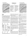
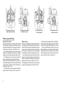
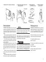
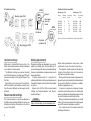
Owners Manual
Öhlins shock absorbers, Car Rally & Track
Including:
How the
shocks works
Setting up
the car
Making
adjustments
Trouble
shooting
Maintenance
Inspection
1
Safety signals
Important information concerning safety is
distinguished in this manual by the
following notations:
The Safety alert symbol means:
Caution! Your safety is involved.
WARNING!
Failure to follow warning instructions
could result in severe or fatal injury
to anyone working with, inspecting or
using the suspension, or to bystanders.
CAUTION!
Caution indicates that special precautions must be taken to avoid damage to the suspension.
NOTE!
This indicates information that is of
importance with regard to procedures.
© Öhlins Racing AB.
All rights reserved.
Any reprinting or unauthorized use
without the written permission of
Öhlins Racing AB is prohibited.
Printed in Sweden.
2
Introduction
All of Öhlins advanced suspension products are
adepted to the specific brand and model. This
means that length, travel springaction and damping
characteristics, are tested individually just for the
vehicle that you have decided to fit with Öhlins suspension.
Before installation
Öhlins Racing AB can not be held responsible for
any damage whatsoever to suspension or vehicle,
or injury to persons, if the instructions for fitting
and maintenance are not followed exactly.
Similarly, the warranty will become null and void
if the instructions are not adhered to.
Contents
Safety ............................................................. 2
Design ............................................................ 3
When you are driving ...................................... 4
External adjusters ........................................... 5
Setting up your car ......................................... 5
Camber bushing ............................................. 6
Making adjustments ....................................... 6
Maintenance, inspection ................................. 7
WARNING!
1. Installing a suspension, that is not
approved by the vehicle manufacturer, may
affect the stability of your vehicle. Öhlins
Racing AB cannot be held responsible for
any personal injury or damage whatsoever
that may occur after fitting the suspension.
Contact an Öhlins dealer or other qualified
person for advice.
2. Please study and make certain that you
fully understand all the mounting instructions
and the owners manuals before handling this
suspension kit. If you have any questions
regarding proper installation procedures,
contact an Öhlins dealer or other qualified
person.
3. The vehicle service manual must be referred
to when installing the Öhlins suspension.
NOTE
Öhlins products are subject to continual improvement and development. Consequently, although
these instructions include the most up-to-date
information available at the time of printing, there
may be minor differences between your suspension and this manual. Please consult your Öhlins
dealer if you have any questions with regard to
the contents of the manual.
Effect of rebound adjuster
(m = increased number of clicks)
da
bo
Re
ping
◗
s
pres
0
Com
am
ion d
0
Piston speed (m/s)
Öhlins car shock absorbers are based on Öhlins
successful application of the high pressure monotube
concept. In short, that means that the damping oil is
put under gas pressure, and separated from the gas
by a floating piston.The separating piston is
positioned in an external reservoir (Fig.1).
To obtain a progressive damping system (PDS),
the most advanced shock absorber has two pistons. One of the pistons is active throughout the
Oil
Gas
Shock
absorber
piston
2.
With the bleed valve on
the top of the reservoir,
you adjust compression
damping. The valve
restricts the flow to the
reservoir, not from it,
thereby only influencing
the compression
damping.
0,5
Design
PDS
piston
1.
At low shaft speeds the
damping oil is forced
through an adjustable
bleed valve in the piston
shaft. The valve affects
mainly rebound
damping and has only a
small effect on
compression damping.
Separating
piston
1. Shock absorber with external gas reservoir.
Damping force (N)
Damping force (N)
in
mp
g
pin
am
d
nd
0
entire lenght of the stroke, while the second piston begins to work in the event of powerful compression of the shock absorber.
The high pressure monotube concept has many
advantages. It prevents the risk of cavitation, that
can wear out internal components and cause inconsistent damping. It eliminates aeration of the damping oil, which also causes inconsistent damping.
It improves the cooling, because the oil is in direct
contact with the outer tubing. It gives more consistent
damping, regardless of the shock absorber’s working temperature, and it makes the shock absorber
last longer.
The external shock absorber reservoir, connected
directly to the shock absorber body or by a hose, is
in fact an ”extension” of the main body which
contributes to the improved cooling. The reservoir
contains the floating piston and the gas that pressurises the damping oil.
Function
At low shaft speeds the damping oil is forced through
an adjustable bleed valve in the main piston shaft.
The valve affects mainly rebound damping and has
◗
ing
p
u
dam
bo
ion
Re
ress
p
Com
0
◗
g
und
Effect of compression adjuster
(m = increased number of clicks)
2. Damping curves
Piston speed (m/s)
0,5
only a small effect on compression damping, see fig
1, graph 1 above.
The adjuster is connected to the valve via an
aluminium shaft, that runs inside the piston shaft.
When the temperature in the shock increases the
aluminium shaft extends, thereby closing the
bleed valve gradually.
This diminishes the influence of the oil viscosity
changes due to temperature, keeping the flow
through the valve virtually the same, regardless of
temperature.
With the second adjustable bleed valve, on the
top of the reservoir, you can adjust the compression
damping. Some models have separate high and low
speed compression clamping.
The valve restricts the flow to the reservoir but not
from it, thereby only influencing the compression
damping, see fig 2, graph 2 above.
At higher shaft speeds the damping forces are
primarily controlled by the main piston and its
compression and rebound shim stacks. By
changing the numbers, diameter, and thickness of
the shims in the stack and by using different jets in
the valves, your Öhlins shock absorbers are tailormade for just your car.
3
1. Compression flow in
shock absorber body
2. Compression flow in
external reservoir
3. Rebound flow in
shock absorber
4. Rebound flow in
externa reservoir
When you are driving
On a smooth surface
When you are driving on a smooth surface and the
shock absorbers are compressed slowly (low shaft
speed), the damping oil is forced only through the
adjuster valve in the piston shaft, (Fig.1), flow 3.
The oil displaced by the piston shaft is forced
through the independent compression damping
adjuster out into the external reservoir, (Fig.2), flow 3.
The floating piston in the reservoir is forced to
move, compressing the gas behind it further.
When the shock absorber extends, the pressure
behind the floating piston will force the oil through
a one-way valve, and back into the shock absorber
body, (Fig.4), flow 1 and 2.
The oil beneath the piston returns through the
adjuster valve in the piston shaft, (Fig.3), flow 3.
4
Hitting a bump
When you are hitting a bump the shock absorbers
are compressed fast (high shaft speed). The oil can
not be forced ”fast enough” through just the valve in
the piston shaft. The pressure on the compression
side increases and opens the shim stack covering
the compression orifices in the piston, (Fig.1), flow 2.
Also, oil displaced by the piston shaft can not be
forced ” fast enough” through just the valve in the
reservoir. The pressure increases and a shim stack,
parallel to the valve, opens, (Fig.2), flow 1 and 2.
The floating piston is forced to move, compressing
the gas by the displacement of the piston shaft.
When the shock absorber extends, the floating
piston forces the oil through the one-way valve back
into the shock absorber body, (Fig.3), flow 1 and 2.
The pressure difference over the piston is still
high and the flow can not be forced ”fast enough”
through just the valve in the piston shaft. The shim
stack covering the rebound orifices in the piston
opens and the oil returns, (Fig.4), flow 1.
5. Adjustment of compression damping
6. High and low speed compression
damping adjusters
7. Rebound adjuster
on Mc Pherson strut
8. Rebound adjuster
on piston shaft
Low speed
+
+
+
-
+
Added
damping force
-
Reduced
damping force
High speed
External adjusters
The Öhlins shock absorbers have a low speed
compression adjustment knob located on top
of the reservoir (Fig.5). Some models even have
a high and low speed compression adjustment
(Fig.6).
A low speed rebound adjuster is located in the
bottom end of the Öhlins McPherson strut.
Adjustments are made with a 3 mm Allen key (fig 7).
On the Öhlins shock absorber, the rebound
adjustment knob is located at the end eye of the
piston shaft (Fig.8) .
The temperature compensation system of the
rebound adjuster reduces the number of clicks
(due to the elongation of the aluminium shaft, as
described earlier) when the shock absorber is
hot.
Therefore, always make changes from the
previous click position without first closing the
adjuster.
To count the number of clicks you are using, first
let the shock cool down to ambient temperature.
+
-
Setting up your car
NOTE!
Using to much force when closing the adjuster
will destroy important sealing surfaces. When
possible use no tool, simply your fingers.
All the adjusters have a normal right-hand thread.
Click position zero (0) is when the adjusters are
turned clockwise to fully closed.
WARNING!
There is no stop telling when the adjusters are fully
open. It is possible to unscrew the strut rebound
adjuster if more than the recommended usable
clicks are used. Please see ”Setting up your car”.
Installing new shock absorbers may alter ride
height, wheel angles etc. on your car. Therefore, it
is wise to do a complete resetting of the car after
you have installed the Öhlins shock absorbers.
Perform the following steps and always make
notes before using the shock absorber:
1. Check ride height front and rear.
Adjust if necessary.
2. Check corner weight front and rear,if scales
are available.
Adjust if necessary.
3. Check all wheel angles front and rear.
Adjust if necessary.
5
9. Camber bushings
Camber bushings available
5194
Bushing type 5194
Part no.
Marking
grooves
Groove
Bushing type 5194
Hole away
from the
wheel
5794
Hole facing
the wheel
05194-00
05194-05
05194-10
05194-15
05194-20
05194-25
05194-80*
0
1
2
3
4
5
Eccentricity
in mm
0
0.5
1.0
1.5
2.0
2.5
Bushing type 5794
Part no.
Eccentricity
in mm
05794-00
05794-01
05794-02
05794-03
05794-04
05794-05
3.00
2.44
1.88
1.32
0.76
0.20
*No hole, the customer can drill the hole to tailor camber exactly.
Punched
number (0-5)
Bushing type 5794
Camber bushings
Making adjustments
Unlike most standard McPherson struts, the
Öhlins struts feature camber bushings that enable
you to alter the wheel camber.
The different bushings are marked: bushing
type 5194 with grooves; bushing type 5794 with
a punched number on the side (last figure of the
Part No.).
Depending on how you mount the bushings,
with the eccentric hole facing the wheel or away
from the wheel, different camber angles will be
obtained.
Suspension settings are dependent on your car’s
weight, your driving style, road conditions etc. If
you are not happy with our recommended settings,
here are a few guidelines and ground rules how to
make adjustments.
To make improvements, it is important to
understand the function of the shock absorbers and
through testing learn how they affect the handling
of your car.
Always start with the Öhlins recommended
settings, see ”External adjusters” and ”Recommended settings”.
Recommended settings
The shock absorbers in your kit are adjusted to
the Öhlins recommended setting for your car, see
Mounting instructions. We advise you to use this
as your start setting.
6
NOTE!
Higher click numbers give less damping force.
When making adjustments; keep notes, make
adjustments one at a time and in small steps.
The adjusters should normally not be adjusted
in steps of more than 2 clicks at a time and not
outside the usable click range.
When you think you have made an improvement,
go back to what you started with and double check
to be sure. Pay attention to changes in conditions
like tires or temperatures, etc.
In general, compression damping changes
should be used to influence the car's stability and
response, while rebound damping changes should
be used to influence comfort and traction.
When you need more damping force, you should
mainly try to increase compression damping and
use as little rebound damping as possible.
This usually means that you gain comfort and
handling performance.
Inspection points:
6
4
5
4
1
Lift the bump rubber and
clean the area below.
3
2
3
Inspection and maintenance
Clean the shock absorbers externally with a soft
detergent . Use compressed air . Be careful that
all dirt and debris is removed.
Lift the bump rubber and clean the area below.
Keep the shock absorbers clean and always
spray them with oil (QS 14, WD40 or CRC 5-56
or similar) after washing the vehicle.
CAUTION!
Never use detergents that can damage the surfaces
of the shock absorber. IA thinner and brake cleaner
will dry the surfaces too much.
After every competition:
Inspection points:
Every 300-500 km (Mc Pherson struts only):
1. Check brackets for possible excessive play.
A. Remove the cartridge from the front outer tube
by removing the bottom nut.
2. Check the piston shaft for leakage and damage.
B. Clean all parts with a soft detergent.
3. Check the shock absorber body and for
external damages.
5. Excessive wear of rubber components.
C. Lubricate the the inner tube and the scraper
with a layer of Öhlins red grease, part No. 14601 (100 grams) or 146-02 (400 grams).
The space between the bushings in the
outer tube should be filled with a layer of Öhlins
red grease up to the bushing surface.
6. Fastening to the vehicle.
D. Assemble the strut and tighten all nuts.
7. Check the hose for leakage and damage.
Once a year:
Change shock absorber oil. Use only Öhlins
shock absorber oil. Contact your Öhlins dealer.
4. Check the external reservoir for damages that
can restrict the floating piston from moving freely.
WARNING!
Never alter the gas pressure. Special-purpose
charging equipment and access to nitrogen is
required. The gas pressure should normally never
be altered.
6
NOTE!
Make certain that your shock absorber are always
filled with Öhlins High performance shock absorber oil
NOTE!
Discarded Öhlins products should be handled
over to an authorized work shop or distributor for
proper disposal.
7
More info
The ultimate suspension site.
Find out everything about your suspension.
Download mounting instructions, manuals and brochures.
And a lot more.
Öhlins Racing AB, Box 722, S-194 27 Upplands Väsby, Sweden
Phone +46 8 590 025 00, Fax +46 8 590 025 80
Your Öhlins dealer:
8
07440-01, Teknisk Illustration, OM Car Rally & Track. Issued 05 04 19.
www.ohlins.com